


Low Profile Swing-Lock Bd.-to-Wire for Power (UL/CSA Certified)
Features
[SnapBee (TM)]
Low Profile [Swing-Lock] Wire-to-Board Connector for Power (UL, C-UL Standard Compliant)
1. Reinforced swing lock design
2. Header lock improves plug retention
3. Highly reliable contact design
4. Insertion guide keys prevent misalignment
5. Solder wicking prevention
6. Case disengagement prevention
7. Cost effective
Document Information
| Document Title | Hirose Electric DF57 Series |
|---|---|
| Document Type | Product Catalog |
| File size | 283.4Kb |
| Company | IIDA ELECTRONICS (Documents List) |
Documents related to this company


Document Contents
Page1
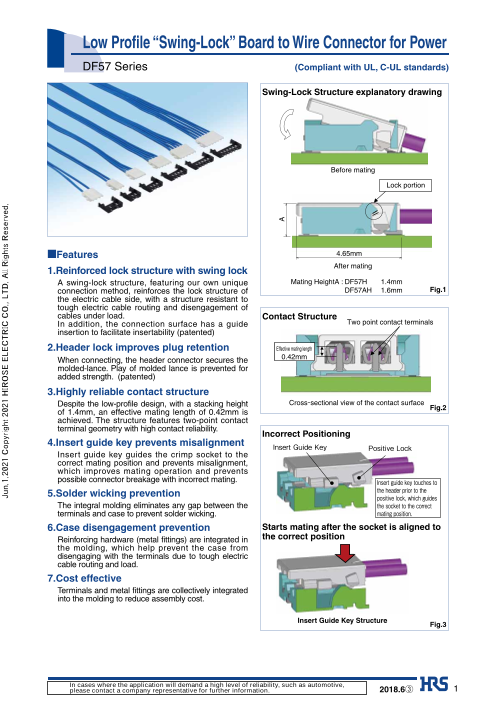
Low Profile “Swing-Lock” Board to Wire Connector for Power
DF57 Series (Compliant with UL, C-UL standards)
Swing-Lock Structure explanatory drawing
Before mating
Lock portion
■Features 4.65mm
1.Reinforced lock structure with swing lock After mating
A swing-lock structure, featuring our own unique Mating HeightA : DF57H 1.4mm
connection method, reinforces the lock structure of DF57AH 1.6mm Fig.1
the electric cable side, with a structure resistant to
tough electric cable routing and disengagement of
cables under load. Contact Structure
In addition, the connection surface has a guide
insertion to facilitate insertability (patented)
2. Header lock improves plug retention
When connecting, the header connector secures the
molded-lance. Play of molded lance is prevented for
added strength. (patented)
3.H ighly reliable contact structure
Despite the low-profile design, with a stacking height
of 1.4mm, an effective mating length of 0.42mm is Fig.2
achieved. The structure features two-point contact
terminal geometry with high contact reliability.
Incorrect Positioning
4. Insert guide key prevents misalignment Insert Guide Key Positive Lock
Insert guide key guides the crimp socket to the
correct mating position and prevents misalignment,
which improves mating operation and prevents
possible connector breakage with incorrect mating. Insert guide key touches to
5. Solder wicking prevention the header prior to the positive lock, which guides
The integral molding eliminates any gap between the the socket to the correct
terminals and case to prevent solder wicking. mating position.
6.C ase disengagement prevention Starts mating after the socket is aligned to
Reinforcing hardware (metal fittings) are integrated in the correct position
the molding, which help prevent the case from
disengaging with the terminals due to tough electric
cable routing and load.
7. Cost effective
Terminals and metal fittings are collectively integrated
into the molding to reduce assembly cost.
Insert Guide Key Structure Fig.3
In cases where the application will demand a high level of reliability, such as automotive,
please contact a company representative for further information. 2018.6③ 1
Jun.1.2021 Copyright 2021 HIROSE ELECTRIC CO., LTD. All Rights Reserved.
A
Page2
DF57 Series●Low Profile “Swing-Lock” Board to Wire Connector for Power
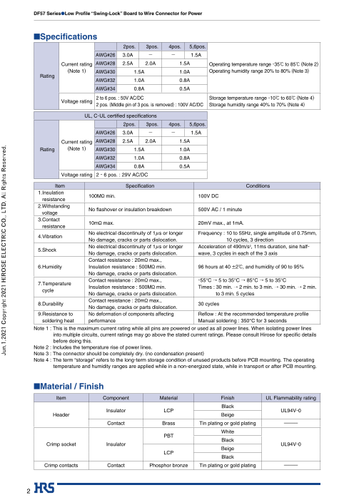
■Specifications
2pos. 3pos. 4pos. 5,6pos.
AWG#26 3.0A _ _ 1.5A
Current rating AWG#28 2.5A 2.0A 1.5A Operating temperature range -35ç to 85ç (Note 2)
(Note 1) AWG#30 1.5A 1.0A Operating humidity range 20% to 80% (Note 3)
Rating
AWG#32 1.0A 0.8A
AWG#34 0.8A 0.5A
2 to 6 pos. : 50V AC/DC Storage temperature range -10ç to 60ç (Note 4)
Voltage rating
2 pos. (Middle pin of 3 pos. is removed) : 100V AC/DC Storage humidity range 40% to 70% (Note 4)
UL, C-UL certified specifications
2pos. 3pos. 4pos. 5,6pos.
AWG#26 3.0A _ _ 1.5A
Current rating AWG#28 2.5A 2.0A 1.5A
Rating (Note 1) AWG#30 1.5A 1.0A
AWG#32 1.0A 0.8A
AWG#34 0.8A 0.5A
Voltage rating 2 - 6 pos. : 29V AC/DC
Item Specifi cation Conditions
1. Insulation
100Mø min. 100V DC
resistance
2.W ithstanding
No fl ashover or insulation breakdown 500V AC / 1 minute
voltage
3. Contact
10mø max. 20mV max., at 1mA.
resistance
No electrical discontinuity of 1µs or longer Frequency : 1 0 to 55Hz, single amplitude of 0.75mm,
4.Vibration
No damage, cracks or parts dislocation. 10 cycles, 3 direction
No electrical discontinuity of 1µs or longer Acceleration of 490m/s2, 11ms duration, sine half-
5.Shock
No damage, cracks or parts dislocation. wave, 3 cycles in each of the 3 axis
Contact resistance : 20mø max.,
6.Humidity Insulation resistance : 500Mø min. 96 hours at 40 ±2ç, and humidity of 90 to 95%
No damage, cracks or parts dislocation.
Contact resistance : 20mø max., -55°C → 5 to 35°C → 85°C → 5 to 35°C
7. Temperature
Insulation resistance : 500Mø min. Times : 30 min. → 2 min. to 3 min. → 30 min. → 2 min.
cycle
No damage, cracks or parts dislocation. to 3 min. 5 cycles
Contact resistance : 20mø max.,
8.Durability 30 cycles
No damage, cracks or parts dislocation.
9. Resistance to No deformation of components affecting Refl ow : A t the recommended temperature profi le
soldering heat performance Manual soldering : 350°C for 3 seconds
Note 1 : This is the maximum current rating while all pins are powered or used as all power lines. When isolating power lines
into multiple circuits, current ratings may go above the stated current ratings. Please consult Hirose for specifi c details
before doing this.
Note 2 : Includes the temperature rise of power lines.
Note 3 : The connector should be completely dry. (no condensation present)
Note 4 : The term “storage” refers to the long-term storage condition of unused products before PCB mounting. The operating
temperature and humidity ranges are applied while in a non-energized state, while in transport or after PCB mounting.
■Material / Finish
Item Component Material Finish UL Flammability rating
Black
Insulator LCP UL94V-0
Header Beige
Contact Brass Tin plating or gold plating ---------
White
PBT
Black
Crimp socket Insulator UL94V-0
Beige
LCP
Black
Crimp contacts Contact Phosphor bronze Tin plating or gold plating ---------
2
Jun.1.2021 Copyright 2021 HIROSE ELECTRIC CO., LTD. All Rights Reserved.
Page3
DF57 Series●Low Profile “Swing-Lock” Board to Wire Connector for Power
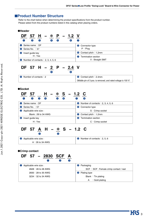
■Product Number Structure
Refer to the chart below when determining the product specifications from the product number.
Please select from the product numbers listed in this catalog when placing orders.
●Header
DF 57 H − * P − 1.2 V
❶ ❷ ❸ ❹ ❺ ❻ ❼
❶ Series name : DF ❺ Connector type
❷ Series No. : 57 P : Plug
❸ Insert guide key ❻ Contact pitch:1.2mm
H : Yes ❼ Termination section
❹ Number of contacts: 2, 3, 4, 5, 6 V : Straight SMT
DF 57 H − 2 P − 2.4 V
❹ ❻
❹ Number of contacts:2 ❻ Contact pitch:2 .4mm
(Middle pin of 3 pos. is removed, and rated voltage is 100 V)
●Socket
DF 57 H − * S − 1.2 C
❶ ❷ ❸ ❹ ❺ ❻ ❼ ❽
❶ Series name :DF ❺ Number of contacts:2, 3, 4, 5, 6
❷ Series No. :57 ❻ Connector type
❸ Applicable wire size : S:Crimp socket
Blank : 28 to 34 AWG ❼ Contact pitch:1.2mm
❹ Insert guide key ❽ Termination section
H : Yes C:Crimp socket
DF 57 A H − * S − 1.2 C
❸ ❺
❸ Applicable wire size : ❺ Number of contacts:2, 5, 6
A:26 to 34 AWG
●Crimp contact
DF 57 − 2830 SCF A
❶ ❷ ❸
❶ Applicable wire size : ❷ Packaging
2628:26 to 28 AWG SCF :SCF : Female crimp contact / reel
2830:28 to 30 AWG ❸ Plating type
3234:32 to 34 AWG Blank :Tin plating
A :Gold plating
3
Jun.1.2021 Copyright 2021 HIROSE ELECTRIC CO., LTD. All Rights Reserved.
Page4
DF57 Series●Low Profile “Swing-Lock” Board to Wire Connector for Power
■Header(SMT)
A
B
Contact No.1 P=1.2
Vacuum area
C
0.25
Above image is 3 pos.
Recommended PCB layout
(Thickness : 1.0mm)
[Specifi cation number] **
(21) : Tin plated, color : black
(23) : Tin plated, color : beige
(51) : Gold plated, color : black
Unit : mm
Part No. HRS No. No. of contacts A B C
DF57H-2P-1.2V(**) 666-0104-7 ** 2 4.1 1.2 2.5
DF57H-3P-1.2V(**) 666-0105-0 ** 3 5.3 2.4 3.7
DF57H-4P-1.2V(**) 666-0106-2 ** 4 6.5 3.6 4.9
DF57H-5P-1.2V(**) 666-0107-5 ** 5 7.7 4.8 6.1
DF57H-6P-1.2V(**) 666-0108-8 ** 6 8.9 6.0 7.3
Note 1 : Embossed tape reel packaging (5,000 pcs/reel).
Note 2 : The crossed-shaded area is a no conductive trace area.
A
B
Contact No.1
Recommended PCB layout
(Thickness : 1.0mm)
Vacuum area
C
0.25
Unit : mm [Specifi cation number] **
Part No. HRS No. No. of contacts A B C (21) : Tin plated, color : black
DF57H-2P-2.4V(**) 666-0109-0 ** 2 5.3 2.4 3.7 (23) : Tin plated, color : beige
4
Jun.1.2021 Copyright 2021 HIROSE ELECTRIC CO., LTD. All Rights Reserved.
4.35 4.35
1.4 4.1 1.4 4.1
2.225 2.225
1.55 1.55
Page5
DF57 Series●Low Profile “Swing-Lock” Board to Wire Connector for Power
●Packaging Specification
DF57H-2P-1.2V(**)
DF57H-3P-1.2V(**) 4±0.1
DF57H-2P-2.4V(**) 2±0.1 8±0.1 E E-E
D ED-D D
DIRECTION OF UNREELING
DF57H-4P-1.2V(**)
DF57H-5P-1.2V(**) 2.125±0.3 4±0.1
DF57H-6P-1.2V(**) (CENTER OF 2±0.1 8±0.1 G G-G
VACUUM AREA)
Unit : mm
F F G Part No. No. of contacts H J
F-F DF57H-4P-1.2V(**) 4 16 7.5
DF57H-5P-1.2V(**) 5 16 7.5
DIRECTION OF UNREELING DF57H-6P-1.2V(**) 6 24 11.5
■Crimp socket
[Specifi cation number] **
Above image is 3 pos. Blank : M aterial : PBT, color : white
(08) : M aterial : LCP, color : beige
(15) : M aterial : LCP, color : black
Unit : mm
Part No. HRS No. No. of contacts A B C D E F
DF57H-2S-1.2C(**) 666-0100-6 ** 2 3.5 2.98 2.6 3.2 1.2 1.2
DF57H-3S-1.2C(**) 666-0012-0 ** 3 4.7 4.18 3.8 4.4 2.4 1.2
DF57H-4S-1.2C(**) 666-0101-9 ** 4 5.9 5.38 5.0 5.6 3.6 1.2
DF57H-5S-1.2C(**) 666-0102-1 ** 5 7.1 6.58 6.2 6.8 4.8 1.2
DF57H-6S-1.2C(**) 666-0103-4 ** 6 8.3 7.78 7.4 8.0 6.0 1.2
Note 1 : The quantity is delivered per pack (1,000 pcs.). Order by number of pack.
■Socket for 26 AWG Unit : mm
Part No. HRS No. No. of contacts A B C D E F
DF57AH-2S-1.2C(**) 666-0112-0 ** 2 3.5 2.98 2.6 3.2 1.2 1.4
DF57AH-5S-1.2C(**) 666-0110-0 ** 5 7.1 6.58 6.2 6.8 4.8 1.4
DF57AH-6S-1.2C(**) 666-0111-2 ** 6 8.3 7.78 7.4 8.0 6.0 1.4
Note 1 : The quantity is delivered per pack (1,000 pcs.). Order by number of pack.
[Specifi cation number] **
Blank : M aterial : PBT, color : black
(10) : M aterial : PBT, color : white
(15) : M aterial : LCP, color : black
5
Jun.1.2021 Copyright 2021 HIROSE ELECTRIC CO., LTD. All Rights Reserved.
16±0.3
H±0.3 7.5±0.1
J±0.1 1.75±0.1 7.375±0.3 1.75±0.1
(CENTER OF
VACUUM AREA)
1
.1 0
.
+
+0 .5 0 0
.5 Ø
1
Ø1
Page6
DF57 Series●Low Profile “Swing-Lock” Board to Wire Connector for Power
■Crimp contact
[Packaging Specifi cation]
Blank : E mbossed tape packaging (40,000 pcs/reel)
(41) : Embossed tape packaging (35,000 pcs/reel)
Part No. HRS No. Packaging Quantity Finish Applicable wire Applicable socket connector
DF57-2628SCF(41) 666-0013-3 41 Reel 35,000 Tin plated
26 to 28 AWG DF57AH-*S-1.2C(**)
DF57-2628SCFA(41) 666-0033-0 41 Reel 35,000 Gold plated
DF57-2830SCF 666-0001-4 Reel 40,000 Tin plated
28 to 30 AWG
DF57-2830SCFA 666-0034-3 Reel 40,000 Gold plated DF57H-*S-1.2C(**)
DF57-3234SCF 666-0016-1 Reel 40,000 Tin plated DF57AH-*S-1.2C(**)
32 to 34 AWG
DF57-3234SCFA Under planning Reel 40,000 Gold plated
Note : Embossed tape reel packaging (40,000 pcs/reel).
Order by number of reels.
●Applicable wire (Tin plated annealed copper wire)
Wire size
Part No. Jacket outer diameter Recommended cable ●Strip length 1.0 to 1.4mm
(Stranded wire conductor)
DF57-2628SCF(41) 26 AWG( 7/Ø0.16mm) UL3302,UL3610
Ø0.88mm max.
DF57-2628SCFA 28 AWG( 7/Ø0.127mm) -----------
DF57-2830SCF 28 AWG( 7/Ø0.127mm) UL1571(Thin wire),
Ø0.5mm ‒ Ø0.63mm
DF57-2830SCFA 30 AWG( 7/Ø0.102mm) UL10584(ETFE wire)
32 AWG( 7/Ø0.08mm)
DF57-3234SCF Ø0.32mm ‒ Ø0.42mm -----------
34 AWG( 7/Ø0.08mm)
Note 1 : When using other than the recommended wire, contact your nearest Hirose sales representative.
Note 2 : The strip length is a reference value. Please make adjustments so fi nished crimps will meet the specifi ed values.
Refer to the crimping quality standards (ATAD-H0404) for details.
BTools
Type Part No. HRS No. Applicable contact
DF57-2628SCF(41)
AP105-DF57-2628S 901-4622-2
DF57-2628SCFA(41)
Applicator AP105-DF57-2830S 901-4618-5 DF57-2830SCF
AP105-DF57-2830SA 901-4645-0 DF57-2830SCFA
AP105-DF57-3234S 901-4629-1 DF57-3234SCF
Press CM-105C 901-0001-0 -----------
Hand crimping tool HT305/DF57-2830HC(Note 2) 902-4635-0 DF57-2830SCF
Contact extraction tool DF-C-PO(B) 550-0179-2 DF57-****SCF(A)
Note 1 : If any trouble has occurred due to tools other than the designated tool, Hirose bears no respoisibility for any trouble.
Note 2 : The compatible wire is limited to UL1571 of thin wire type, 28 to 30 AWG.
6
Jun.1.2021 Copyright 2021 HIROSE ELECTRIC CO., LTD. All Rights Reserved.
Page7
DF57 Series●Low Profile “Swing-Lock” Board to Wire Connector for Power
BUsage Recommendations
1. Recommended temperature
profi le
10secMAX
MAX 250ç
250
220ç
200
180ç
150
100
0
TIME (sec)
90 to 120sec 60secMAX
PRE-HEATING TIME SOLDERING TIME
The temperature profi les are based on the above conditions.
In individual applications the actual temperature may vary,depending on solder paste type, volume/
thickness and board size/thickness. Consult your solder paste and equipment manufacturer for
specifi c recommendations.
2.Recommended manual soldering Manual soldering : 350ç ± 10ç for 3 seconds
3.R ecommended screen thickness and Thickness : 0.1mm
open area ratio (Pattern area ratio) Open area ratio : 100%
4.Board warpage
Maximum of 0.02mm at the connector center, with both ends of the connector as reference points.
5.Cleaning conditions Cleaning is not recommended. When cleaning, please evaluate as if can deteriorate the
performance including mechanical operation and environmental resistance.
■ When inserting crimp-type (solderless) terminals to crimping (solderless) sockets, to maintain
6.Precautions reliable performance, please do not insert obliquely.
■ DO NOT mate/un-mate non-terminated plugs with non-mounted receptacles.
This may lead to damage or deformation of the contacts.
■Removal of the holding electric cable may cause damage so please be careful.
■ DO NOT apply fl ux to the contact terminals when hand soldering the receptacle to the board.
Wicking of the fl ux into the electrical contact areas may lead to connection failures.
■ Slight discoloration on the insulating materials will not affect form, fit or function of the
connectors.
■ Please refer to the documents "DF57 Series Cable assembly Procedure ETAD-H0421", "Crimp
condition" and "DF57-****SCF(A)(**) Crimp quality standards ATAD-H0404" for the cable
assembly procedures.
■P lease refer to the "DF57H Series Mating/Unmating Operation Instruction Manual (ETAD-H0652)"
for the connector operation.
7
Jun.1.2021 Copyright 2021 HIROSE ELECTRIC CO., LTD. All Rights Reserved.
TEMPERATURE(ç)
Page8
DF57 Series●Low Profile “Swing-Lock” Board to Wire Connector for Power
7. I nsertion and removal operation
method Mating
① Determine position, fitting ② Insert the cable side ③ Push the contact portion side
the external form
Un-mating
① Engage lever ② Pull up and release the ③ T he reinforced lock is also released
simple lock and the un-mating is complete
8. Mating compatibility
DF57H DF57
Header
DF57H DF57 DF57H DF57
Socket
Mating compatibility Y Y N Y
Additional guiding
Y N - N
keys
® 2-6-3,Nakagawa Chuoh,Tsuzuki-Ku,Yokohama-Shi 224-8540,JAPAN
TEL: +81-45-620-3526 Fax: +81-45-591-3726
http://www.hirose.com
http://www.hirose-connectors.com
The characteristics and the specifications contained herein are for reference purpose. Please refer to the latest customer drawings prior to use.
8 The contents of this catalog are current as of date of 06/2018. Contents are subject to change without notice for the purpose of improvements.
Jun.1.2021 Copyright 2021 HIROSE ELECTRIC CO., LTD. All Rights Reserved.