0.175mm Pitch, 0.65mm Height, Bottom Contact, Double-sided Lead, Back Flip/Front Axis™, FPC Connector
TF20 Series
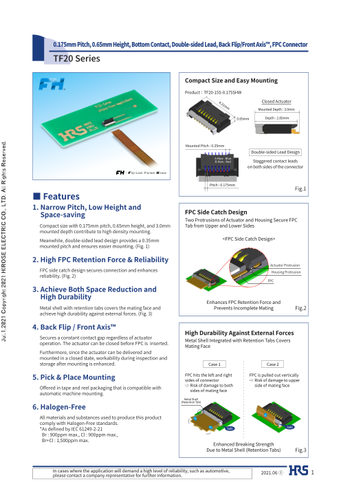
Compact Size and Easy Mounting
Product:TF20-15S-0.175SHW
4.3 Closed Actuator1mm Mounted Depth : 3.0mm
0.65mm Depth : 2.85mm
Mounted Pitch : 0.35mm
Double-sided Lead Design
A-Row : Blue
B-Row : Red Staggered contact leads
on both sides of the connector
Pitch : 0.175mm
Fig.1
■ Features
1. Narrow Pitch, Low Height and
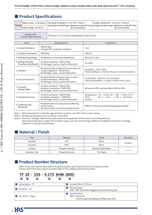
Space-saving FPC Side Catch Design
Two Protrusions of Actuator and Housing Secure FPC
Compact size with 0.175mm pitch, 0.65mm height, and 3.0mm Tab from Upper and Lower Sides
mounted depth contribute to high density mounting.
Meanwhile, double-sided lead design provides a 0.35mm <FPC Side Catch Design>
mounted pitch and ensures easier mounting. (Fig. 1)
2. High FPC Retention Force & Reliability
Actuator Protrusion
FPC side catch design secures connection and enhances Housing Protrusion
reliability. (Fig. 2)
FPC
3. A chieve Both Space Reduction and
High Durability
Enhances FPC Retention Force and
Metal shell with retention tabs covers the mating face and Prevents Incomplete Mating Fig.2
achieve high durability against external forces. (Fig. 3)
4. Back Flip / Front Axis™
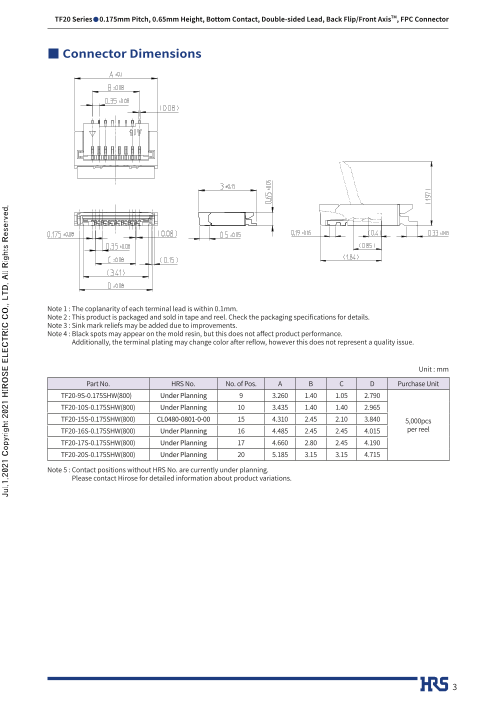
High Durability Against External Forces
Secures a constant contact gap regardless of actuator
operation. The actuator can be closed before FPC is inserted. Metal Shell Integrated with Retention Tabs Covers Mating Face
Furthermore, since the actuator can be delivered and
mounted in a closed state, workability during inspection and
storage after mounting is enhanced. Case 1 Case 2
5. Pick & Place Mounting FPC hits the left and right FPC is pulled out verticallysides of connector ⇨ Risk of damage to upper
Offered in tape and reel packaging that is compatible with ⇨ Risk of damage to both side of mating face
automatic machine mounting. sides of mating face
Metal Shell
(Retention Tab)
6. Halogen-Free
All materials and substances used to produce this product
comply with Halogen-Free standards.
* As defined by IEC 61249-2-21 Safe Safe
Br : 900ppm max., Cl : 900ppm max.,
Br+Cl : 1,500ppm max.
Enhanced Breaking Strength
Due to Metal Shell (Retention Tabs) Fig.3
In cases where the application will demand a high level of reliability, such as automotive,
please contact a company representative for further information. 2021.06 ① 1
Jul.1.2021 Copyright 2021 HIROSE ELECTRIC CO., LTD. All Rights Reserved.
TF20 Series●0.175mm Pitch, 0.65mm Height, Bottom Contact, Double-sided Lead, Back Flip/Front AxisTM, FPC Connector
■ Product Specifications
Rated Current : 0.15A (Note 1) Operating Temperature : -55 to +85 °C (Note 2) Storage Temperature : -10 to +50 °C (Note 3)
Ratings Operating Humidity Range : Relative humidity 90% Max. Storage Humidity Range : Relative humidity 90% Max.
Rated Voltage : 30V AC/DC (No condensation) (No condensation)
Adaptive FPC
Contact Specifications Thickness : 0.12±0.02mm Gold plated Contact Traces
Items Specifications Conditions
1. Contact Resistance 300mΩ Max.Includes FPC conductor resistance 1mA
2. Insulation Resistance 50MΩ Min. 100V DC
3. Withstanding Voltage No flashover or insulation breakdown 90V AC for 1 min.
4. M ating Durability Contact resistance : 300mΩ Max.
(Insertion/withdrawal) No damage, cracks, or parts dislocation. 10 cycles
No electrical discontinuity for more than 1μs.
5. Vibration Contact resistance : 300mΩ Max. Frequency : 10 to 55Hz,
No damage, cracks, or parts dislocation Total Amplitude 1.5mm for 2hours in 3 axis directions
No electrical discontinuity of 1㎲ or more 2
6. Shock Resistance Contact resistance : 300mΩ Max. Acceleration : 981m/s , 6ms duration,
No damage, cracks, or parts dislocation. Sine half-waveform, 3 cycles in each of the 3 axis.
7. H umidity Contact resistance : 300mΩ Max.
(Steady State) Insulation resistance : 50MΩ Min. 96 hours at 40℃ and humidity of 90% to 95%No damage, cracks, or parts dislocation
Contact resistance : 300mΩ Max. Temperature : -55 → +15 to +35 → +85 → +15 to +35 ℃
8. Temperature Cycle Insulation resistance : 50MΩ Min. Time : 30 → 2 to 3 → 30 → 2 to 3 min.
No damage, cracks, or parts dislocation 5 cycles
9. Soldering Heat No deformation of components affecting
Resistance performance Reflow : At the recommended temperature profile No abnormality in electrical performance
Note 1 : When passing the current through all of the contacts, use 70% of the current rating.
Note 2 : Includes temperature rise caused by current flow.
Note 3 : The term “storage” refers to products stored for long period of time prior to mounting and use.
Operating temperature range and humidity range cover non-conducting condition of installed connectors in storage,
shipment or during transportation.
■ Material / Finish
Part Material Finish Remarks
Insulator LCP Black
UL94V-0
Actuator PA9T Black
Contact Phosphor Bronze Partially Gold Plated
Retention Tab Phosphor Bronze Tin Plated
■ Product Number Structure
Refer to the chart below when determining the product specifications from the product number.
Please select from the product numbers listed in this catalog when placing orders.
TF 20 - 15S - 0.175 SHW (800)
1 2 3 4 5 6
1 Series Name : TF 4 Contact Pitch : 0.175mm
2 Series No. : 20 5 Terminal TypeSHW : SMT Horizontal Staggered Array Mounting Type
6 Specifications
3 No. of Pos. : 15pos. (800) : S tandard,
Emboss tape packaging (5,000pcs per reel)
2
Jul.1.2021 Copyright 2021 HIROSE ELECTRIC CO., LTD. All Rights Reserved.
TF20 Series●0.175mm Pitch, 0.65mm Height, Bottom Contact, Double-sided Lead, Back Flip/Front AxisTM, FPC Connector
■ Connector Dimensions
Note 1 : The coplanarity of each terminal lead is within 0.1mm.
Note 2 : This product is packaged and sold in tape and reel. Check the packaging specifications for details.
Note 3 : Sink mark reliefs may be added due to improvements.
Note 4 : Black spots may appear on the mold resin, but this does not affect product performance.
Additionally, the terminal plating may change color after reflow, however this does not represent a quality issue.
Unit : mm
Part No. HRS No. No. of Pos. A B C D Purchase Unit
TF20-9S-0.175SHW(800) Under Planning 9 3.260 1.40 1.05 2.790
TF20-10S-0.175SHW(800) Under Planning 10 3.435 1.40 1.40 2.965
TF20-15S-0.175SHW(800) CL0480-0801-0-00 15 4.310 2.45 2.10 3.840 5,000pcs
TF20-16S-0.175SHW(800) Under Planning 16 4.485 2.45 2.45 4.015 per reel
TF20-17S-0.175SHW(800) Under Planning 17 4.660 2.80 2.45 4.190
TF20-20S-0.175SHW(800) Under Planning 20 5.185 3.15 3.15 4.715
Note 5 : Contact positions without HRS No. are currently under planning.
Please contact Hirose for detailed information about product variations.
3
Jul.1.2021 Copyright 2021 HIROSE ELECTRIC CO., LTD. All Rights Reserved.
TF20 Series●0.175mm Pitch, 0.65mm Height, Bottom Contact, Double-sided Lead, Back Flip/Front AxisTM, FPC Connector
Recommended Land / Metal Mask Dimensions
Recommended Metal Mask Thickness:0.1mm
Unit : mm
Part No. HRS No. No. of Pos. A B
TF20-9S-0.175SHW(800) Under Planning 9 5.0 4.0
TF20-10S-0.175SHW(800) Under Planning 10 5.0 5.0
TF20-15S-0.175SHW(800) CL0480-0801-0-00 15 8.0 7.0
TF20-16S-0.175SHW(800) Under Planning 16 8.0 8.0
TF20-17S-0.175SHW(800) Under Planning 17 9.0 8.0
TF20-20S-0.175SHW(800) Under Planning 20 10.0 10.0
Note 1 : Contact positions without HRS No. are currently under planning.
Please contact Hirose for detailed information about product variations.
4
Jul.1.2021 Copyright 2021 HIROSE ELECTRIC CO., LTD. All Rights Reserved.
TF20 Series●0.175mm Pitch, 0.65mm Height, Bottom Contact, Double-sided Lead, Back Flip/Front AxisTM, FPC Connector
Recommended FPC Dimensions
Unit : mm
Part No. HRS No. No. of Pos. A B C D
TF20-9S-0.175SHW(800) Under Planning 9 2.350 1.400 4 5
TF20-10S-0.175SHW(800) Under Planning 10 2.525 1.575 5 5
TF20-15S-0.175SHW(800) CL0480-0801-0-00 15 3.400 2.450 7 8
TF20-16S-0.175SHW(800) Under Planning 16 3.575 2.625 8 8
TF20-17S-0.175SHW(800) Under Planning 17 3.750 2.800 8 9
TF20-20S-0.175SHW(800) Under Planning 20 4.275 3.325 10 10
Note 1 : Contact positions without HRS No. are currently under planning.
Please contact Hirose for detailed information about product variations.
5
Jul.1.2021 Copyright 2021 HIROSE ELECTRIC CO., LTD. All Rights Reserved.
TF20 Series●0.175mm Pitch, 0.65mm Height, Bottom Contact, Double-sided Lead, Back Flip/Front AxisTM, FPC Connector
FPC Construction (Recommended Specifications)
● F PC : Flexible Printed Circuit
Material Name Material Thickness(㎛)
Covering layer film Polyimide 1mil (12.5)
Cover adhesive (25)
Surface treatment Nickel 1 to 5㎛ + 4
Gold plating
Copper foil CU 1/2 oz 18
Base adhesive Thermoset adhesive
Base film Polyimide 1mil 25
Reinforcement Thermoset adhesive 30
material adhesive
Stiffener Polyimide 5mil 50
Total 127
NOTE 1 : The material composition of FPC is for reference. Please make the thickness of the FPC mating section 0.12±0.02mm
in reference to the above FPC construction.
NOTE 2 : For details about component configuration, please contact a FPC manufacturer.
6
Jul.1.2021 Copyright 2021 HIROSE ELECTRIC CO., LTD. All Rights Reserved.
TF20 Series●0.175mm Pitch, 0.65mm Height, Bottom Contact, Double-sided Lead, Back Flip/Front AxisTM, FPC Connector
Packaging Specifications
● Embossed Carrier Tape Dimensions
● Reel Dimensions
Note 1 : 5,000pcs / Reel (Outer diameter of Reel ø330mm)
Note 2 : Material
1) Emboss tape : PS (Antistatic Treatment)
2) Cover tape : PET (Antistatic Treatment)
Unit : mm
Part No. HRS No. No. of Pos. A B C
TF20-9S-0.175SHW(800) Under Planning 9 7.5 16.0 16.5
TF20-10S-0.175SHW(800) Under Planning 10 7.5 16.0 16.5
TF20-15S-0.175SHW(800) CL0480-0801-0-00 15 7.5 16.0 16.5
TF20-16S-0.175SHW(800) Under Planning 16 7.5 16.0 16.5
TF20-17S-0.175SHW(800) Under Planning 17 7.5 16.0 16.5
TF20-20S-0.175SHW(800) Under Planning 20 7.5 16.0 16.5
Note 3 : Contact positions without HRS No. are currently under planning.
Please contact Hirose for detailed information about product variations.
7
Jul.1.2021 Copyright 2021 HIROSE ELECTRIC CO., LTD. All Rights Reserved.
TF20 Series●0.175mm Pitch, 0.65mm Height, Bottom Contact, Double-sided Lead, Back Flip/Front AxisTM, FPC Connector
Recommended Temperature Profile
HRS Test Conditions
Reflow Method : Reflow, IR/hot air
Reflow Environment : Room air
Solder Composition : Paste, 96.5%Sn/3%Ag/0.5%Cu
(M705-221CM5-32-10.5 from Senju Metal Industry Co., Ltd.)
Test Board : Glass epoxy 50mm×25mm×1mm thick
Land Dimensions : Check the recommended land
dimensions for details.
Metal Mask : Check the recommended metal mask
dimensions for details.
The temperature profile is based on the above conditions.
Please check the mounting conditions before use,
conditions such as solder paste types, manufacturer,
PCB size and any other soldering materials may alter the
performance of such materials.
8
Jul.1.2021 Copyright 2021 HIROSE ELECTRIC CO., LTD. All Rights Reserved.
TF20 Series●0.175mm Pitch, 0.65mm Height, Bottom Contact, Double-sided Lead, Back Flip/Front AxisTM, FPC Connector
Connector Operation and Precautions
Board Mounting Precautions FPC Insertion and Mating Precautions
● Board Warpage ● Actuator Operation
Be sure to minimize the board warpage as much as 1. D o not apply excessive force when releasing the actuator
possible. The lead co-planarity is 0.1mm or less. from the initial position (without FPC inserted).
Too much board warpage may result in soldering failures Inserting a nail or finger as shown in the below picture may
or co-planarity issues. result in terminal deformation.
● Connector Load
Do not apply a force of 0.5N or more to the connector
before mounting it on the board in order to prevent
connector damage.
Do not insert the FPC or operate the connector before
mounting.
● Board Load
• Splitting a large board into several pieces
• S crewing the board
Avoid the handling described above so that no 2. The actuator rotates around the rotational axis as
excessive force is exerted on the board during the shown below. Please rotate the actuator.
assembly process.
Otherwise, the connector may become defective.
● Acceptable Amount of Board Warpage
A 100mm wide board has an acceptable warp range of
0.5mm or less. (Below)
Excessive amounts of warping will place stress on the
connector which may result in damage and malfunction.
3. Please do not push the actuator downwards with
a force of 0.3N force or more as shown below.
Otherwise, the actuator may fall off or be damaged.
9
Jul.1.2021 Copyright 2021 HIROSE ELECTRIC CO., LTD. All Rights Reserved.
TF20 Series●0.175mm Pitch, 0.65mm Height, Bottom Contact, Double-sided Lead, Back Flip/Front AxisTM, FPC Connector
FPC Insertion and Mating Precautions FPC Insertion and Mating Precautions
4. T he actuator is not designed to open more than 105°. ● Inserting the FPC
Do not apply any force to open it beyond this point.
Doing so may result in actuator damage or breakage. 1. I nsert the FPC horizontally along the surface and at right angle to the connector.
Insert it completely to the end.
If the FPC is incorrectly inserted at a diagonal the
conductors may short-circuit due to pitch shift misalign-
ment or the edge of the FPC may catch in the terminals
resulting in deformation of the terminal deformation.
This connector has a ZIF structure and its effective mating
length is 1.87mm.
(when the recommended FPC nominal is used)
Use the actuator carefully to prevent the FPC from shifting
after insertion.
5. Operate the actuator towards the center.
It may break if operated on one side of the actuator 2. D o not insert the FPC diagonally from above.
with FPC inserted. If the FPC is incorrectly inserted at a diagonal as shown
in the above FPC insertion process, the FPC may be bent,
resulting in pattern breakage or insufficient FPC insertion
6. Do not pull or pick the actuator to lift it as shown below. which may cause conduction failure.
Failure to do so may result in connector breakage.
(Do not carry out any operation other than rotating
the actuator as shown in 2 on the previous page.)
• Secure sufficient FPC insertion space during layout
design to prevent incorrect FPC insertion.
Additionally, if the FPC is too short it will make insertion
difficult so please design an appropriate component
layout.
● Contact Orientation
This connector utilizes bottom contacts. Insert the • M ake adjustments with the FPC manufacturer for
FPC with the exposed conductors face down. bending performance and breakage resistance.
● Ensuring a Completed Connection
After completing the locking operation, check that the
actuator is horizontal to the board surface.
Do not apply excessive force when the actuator reaches 0°,
doing so may damage the terminals.
(Allowable force: 1N Max.)
10
Jul.1.2021 Copyright 2021 HIROSE ELECTRIC CO., LTD. All Rights Reserved.
TF20 Series●0.175mm Pitch, 0.65mm Height, Bottom Contact, Double-sided Lead, Back Flip/Front AxisTM, FPC Connector
Instructions on FPC Layout after Mating Other Precautions
● Load to FPC ● Manual Soldering
Do not apply direct force to the connector during FPC Follow the instructions listed below when soldering the
routing. Contact failure, disconnection or breakage may connector manually during repair work, etc.
occur when using a FPC bent near the connector.
In general the FPC should not be bent sharply near the 1. Do not perform reflow soldering or manual soldering
insertion opening. Secure the FPC when applying a with the FPC inserted into the connector.
continuous load.
2. D o not overheat the connector. Do not allow the
soldering iron to contact any part other than the
intended connector leads.
Otherwise, the connector may be deformed or melted.
3. D o not use excessive solder (or flux).
If excessive solder (or flux) is used on the terminals,
solder or flux may adhere to the contacts or the rotating
parts of the actuator, resulting in poor contact or a
rotation failure of the actuator.
FPC Removal Precautions
Release the actuator at approximately the center.
The actuator may break if operated at one side with the
FPC inserted.
Remove the FPC with the actuator released.
11
Jul.1.2021 Copyright 2021 HIROSE ELECTRIC CO., LTD. All Rights Reserved.
TF20 Series●0.175mm Pitch, 0.65mm Height, Bottom Contact, Double-sided Lead, Back Flip/Front AxisTM, FPC Connector
While Taking into Consideration
Specifications mentioned in this catalog are reference values.
When considering to order or use this product, please confirm the Drawing and Product Specifications sheets.
Use an appropriate cable when using the connector in combination with cables.
If considering usage of a non-specified cable, please contact your sales representative.
If assembly process is done by jigs & tools which are not identified by Hirose, assurance will not be given.
If considering usage for below mentioned applications, please contact your sales representative.
In cases where the application will demand a high level of reliability, such as automotive, medical instruments, public infrastructure,
aerospace/ defense etc. Hirose must review before assurance of reliability can be given.
2-6-3,Nakagawa Chuoh,Tsuzuki-Ku,Yokohama-Shi 224-8540,JAPAN
https://www.hirose.com/
12 The contents of this catalog are current as of date of 06/2021. Contents are subject to change without notice for the purpose of improvements.
Jul.1.2021 Copyright 2021 HIROSE ELECTRIC CO., LTD. All Rights Reserved.