


0.92mm mated height Low Height and Light Weight Miniature Coaxial Connectors Supporting up to 30GHz
Features
0.92mm mated height Low Height and Light Weight Miniature Coaxial Connectors Supporting up to 30GHz
1. Supports up to 30GHz
2. Mated Height of 0.92mm (1.0mm Max.)
3. Ultra lightweight
4. Automatic Board Placement
5. 50ohm Ultra-fine coaxial (fluorinated resin insulated) cables
6. Tactile Lock
7. Simple Connector Mating and Unmating
Document Information
| Document Title | Hirose Electric C.FL Series |
|---|---|
| Document Type | Product Catalog |
| File size | 350.3Kb |
| Company | IIDA ELECTRONICS (Documents List) |
Documents related to this company


Document Contents
Page1
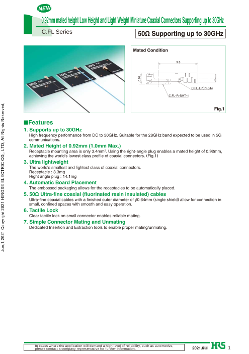
C.FL Series 50Ω Supporting up to 30GHz
Mated Condition
3.3
C.FL-LP(P)-044
C.FL-R-SMT-1
Fig.1
■Features
1. Supports up to 30GHz
High frequency performance from DC to 30GHz. Suitable for the 28GHz band expected to be used in 5G
communications.
2. Mated Height of 0.92mm (1.0mm Max.)
Receptacle mounting area is only 3.4mm2. Using the right-angle plug enables a mated height of 0.92mm,
achieving the world's lowest class profile of coaxial connectors. (Fig.1)
3. Ultra lightweight
The world's smallest and lightest class of coaxial connectors.
Receptacle : 3.3mg
Right angle plug : 14.1mg
4. Automatic Board Placement
The embossed packaging allows for the receptacles to be automatically placed.
5. 50Ω Ultra-fine coaxial (fluorinated resin insulated) cables
Ultra-fine coaxial cables with a finished outer diameter of Ø0.64mm (single shield) allow for connection in
small, confined spaces with smooth and easy operation.
6. Tactile Lock
Clear tactile lock on small connector enables reliable mating.
7. Simple Connector Mating and Unmating
Dedicated Insertion and Extraction tools to enable proper mating/unmating.
In cases where the application will demand a high level of reliability, such as automotive,
please contact a company representative for further information. 2021.6③ 1
Jun.1.2021 Copyright 2021 HIROSE ELECTRIC CO., LTD. All Rights Reserved.
0.92
Page2
C.FL Series●0.92mm mated height Low Height and Light Weight Miniature Coaxial Connectors Supporting up to 30GHz
■Product Specifi cations
Nominal characteristic impedance 50Ω Operating Temperature -40 to +90℃ (90%RH Max.)
Ratings
Frequency Range : DC to 30GHz Storage Humidity Range -20 to +70℃ (90%RH Max.)
Item Specifications Conditions
1. Contact Resistance Center : 60mΩ Max. Exterior : 20mΩ Max. Measured at a maximum of 10mA
2. Insulation Resistance 500MΩ min Measured at 100V DC
3. Withstanding Voltage There shall be no flashover or dielectric breakdown Apply 200V for 1 minute
1.4 Max. DC to 15GHz
4. V.S.W.R.* 1.5 Max. 15 to 20GHz
1.6 Max. 20 to 30GHz
Contact Resistance Center : 65mΩ Max.
5. Durability 20 mating cycles
Exterior : 25mΩ Max.
*V.S.W.R. Measuring System
The above V.S.W.R. specification values are measured using the measurement system below.
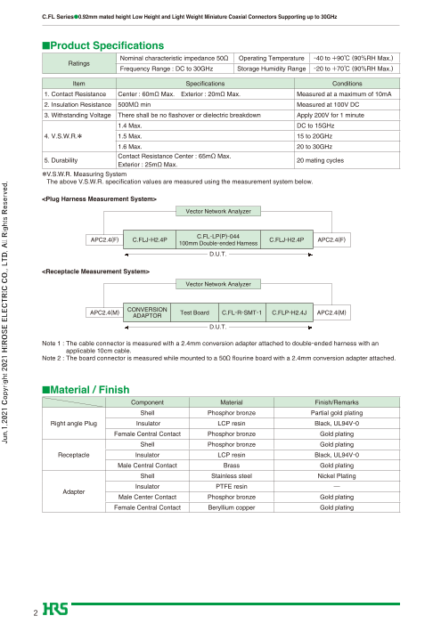
<Plug Harness Measurement System>
Vector Network Analyzer
C.FL-LP(P)-044
APC2.4(F) C.FLJ-H2.4P C.FLJ-H2.4P APC2.4(F)
100mm Double-ended Harness
D.U.T.
<Receptacle Measurement System>
Vector Network Analyzer
CONVERSION
APC2.4(M) Test Board C.FL-R-SMT-1 C.FLP-H2.4J APC2.4(M)
ADAPTOR
D.U.T.
Note 1 : The cable connector is measured with a 2.4mm conversion adapter attached to double-ended harness with an
applicable 10cm cable.
Note 2 : The board connector is measured while mounted to a 50Ω flourine board with a 2.4mm conversion adapter attached.
■Material / Finish
Component Material Finish/Remarks
Shell Phosphor bronze Partial gold plating
Right angle Plug Insulator LCP resin Black, UL94V-0
Female Central Contact Phosphor bronze Gold plating
Shell Phosphor bronze Gold plating
Receptacle Insulator LCP resin Black, UL94V-0
Male Central Contact Brass Gold plating
Shell Stainless steel Nickel Plating
Insulator PTFE resin ―
Adapter
Male Center Contact Phosphor bronze Gold plating
Female Central Contact Beryllium copper Gold plating
2
Jun.1.2021 Copyright 2021 HIROSE ELECTRIC CO., LTD. All Rights Reserved.
Page3
C.FL Series●0.92mm mated height Low Height and Light Weight Miniature Coaxial Connectors Supporting up to 30GHz
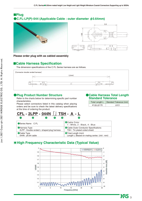
■Plug
●C.FL-LP(P)-044 (Applicable Cable : outer diameter φ0.64mm)
3.3
Please order plug with as cabled assembly
■Cable Harness Specifi cation
The dimension specifications of the C.FL Series harness are as follows.
[Connector double-ended harness]
L(mm)
●Plug Product Number Structure ●Cable Harness Total Length
Refer to the charts below for determining specific part number Standard Tolerance
characteristics.
Total Length L Standard Tolerance (mm)
Please select connectors listed in this catalog when placing
41≦L≦170 ±0.3
orders and be sure to check the latest delivery specifications
at the time of ordering the product.
CFL - 2LPP - 044N「」TSH - A - L
❶ ❷ ❸ ❹ ❺ ❻
❶ ❹Cable ColorSeries Name C.FL
1 : White, 2 : Black, 4 : Blue
❷Harness Type ❺Cable Outer Conductor Specifications
2LPP : Double-ended L-shaped plug harness TSH : Tin plated coiled shield
❸Cable Type ❻Total Length (mm)
044N : Ø0.64 cable Length L (Based on mating center, Unit : mm)
B High Frequency Characteristic Data (Typical Value)
3
Jun.1.2021 Copyright 2021 HIROSE ELECTRIC CO., LTD. All Rights Reserved.
1.92
Page4
C.FL Series●0.92mm mated height Low Height and Light Weight Miniature Coaxial Connectors Supporting up to 30GHz
■Receptacle □Recommended PCB Mounting Pattern
0.3 2.6
GND GND 1.4
GND 0.5
SIG 0.3
1.7
2 No conductive
traces in this
Ø1.4 area
0.43 SIG
Part No. HRS No. Packaging RoHS2
C.FL-R-SMT-1(90) 331-2200-0 90 20,000 pieces per reel ○
●Receptacle Product Number Structure
Refer to the charts below to determine specific part number characteristics.
Please select connectors listed in this catalog when placing orders and be sure to check specifications at the time
of ordering.
C.FL - R - SMT-1 ❶Series Name C.FL
❷Connector Type R : Receptacle
❶ ❷ ❸ ❸Mounting Method SMT-1 : Surface Mounting
B High Frequency Characteristic Data (Typical Value)
●Embossed Tape Specifi cations ●Reel Specifi cations
(JIS C 0806/IEC60286 Standard)
9.5
Pull Direction
2 4
1.5 (0.25)Ø SIG
(0.67)
4
4
Jun.1.2021 Copyright 2021 HIROSE ELECTRIC CO., LTD. All Rights Reserved.
8
3.5 1.75
0.58
1.3
1.7
2
1.3 1.3
0.65
Ø380
1.5
Page5
C.FL Series●0.92mm mated height Low Height and Light Weight Miniature Coaxial Connectors Supporting up to 30GHz
■Conversion Adapter
●2.4mm Conversion Adapter (Mated Portion : C.FL side : Jack-2.4mm side : Plug)
(12.19) 8HEX
M7×0.75-6H
Part No. HRS No. RoHS2
C.FLJ-H2.4P 311-0017-0 ○
Note : The mated portion of the C.FL side has a lower lock retention force than regular products so the adapter cannot be used
for purposes other than performance measurements.
●2.4mm Conversion Adapter (Mated Portion : C.FL side : Plug-2.4mm side : Jack)
13.9
2.4mm Identification 5.6
Groove
M7×0.75-6g
Part No. HRS No. RoHS2
C.FLP-H2.4J 311-0021-0 ○
Note : The mated portion of the C.FL side has a lower lock retention force than regular products so the adapter cannot be used
for purposes other than performance measurements.
●2.92 Conversion Adapter (Mated Portion : C.FL side : Jack-2.92mm side : Plug)
(11.99) 8HEX
1/4-36UNS-2B
Part No. HRS No. RoHS2
C.FLJ-HKP 311-0023-0 ○
Note : The mated portion of the C.FL side has a lower lock retention force than regular products so the adapter cannot be used
for purposes other than performance measurements.
5
Jun.1.2021 Copyright 2021 HIROSE ELECTRIC CO., LTD. All Rights Reserved.
Ø6.35
Page6
C.FL Series●0.92mm mated height Low Height and Light Weight Miniature Coaxial Connectors Supporting up to 30GHz
●2.92 Conversion Adapter (Mated Portion : C.FL side : Jack-2.92mm side : Plug)
13.9
2.92mm Identification
Groove 5.6
1/4-36UNS-2A
Part No. HRS No. RoHS2
C.FLP-HKJ 311-0024-0 ○
Note : The mated portion of the C.FL side has a lower lock retention force than regular products so the adapter cannot be used
for purposes other than performance measurements.
■Insertion and Extraction Tool
Tool for mating and unmating the plug.
Insertion Side Extraction Side
Part No. HRS No. RoHS2
X.FL(V)-LP-IN.OUT 331-0076-0 ○
Note : The insertion and extraction tool may be deformed or damages if dropped, etc. so please handle with care.
6
Jun.1.2021 Copyright 2021 HIROSE ELECTRIC CO., LTD. All Rights Reserved.
(2.6)
(60) 12
Ø6.35
2 3.02
Page7
C.FL Series●0.92mm mated height Low Height and Light Weight Miniature Coaxial Connectors Supporting up to 30GHz
□Usage Precautions
1. Plug
(1) Mating / un-mating ①To un-mate, use the extraction tool X.FL-LP-IN.OUT as shown in the following figure.
[How to un-mate a plug]
X.FL(V)-LP-IN.OUT
Do not un-mate a connector by pulling the cable as it may cause damage to the
connector.
②To mate a connector, use the mating side of the plug mating and unmating tool
X.FL-LPIN. OUT. Align the mating axes between both connectors and check that
the shell is properly aligned. The connector should be inserted perpendicularly as
much as possible. (See the following figure)
(2) Pull forces on the cable Once the connector is mated, do not apply a load to the cable in excess of the values
after connectors are mated indicated in the figure below.
C.FL-LP(P)-044
2N Max.
C.FL-R-SMT-1
Be careful when lifting the cable as it may add a load or cause unmating.
It is recommended to place buffer on the plug when wiring in a direction that causes the
cable to lift. (See figure below)
Buffer
(3)Precautions Do not mate or unmate a connector with an excessive force as it may damage the
connector.
7
Jun.1.2021 Copyright 2021 HIROSE ELECTRIC CO., LTD. All Rights Reserved.
X.FL(V)-LP-IN.OUT
1.05±0.05
Page8
C.FL Series●0.92mm mated height Low Height and Light Weight Miniature Coaxial Connectors Supporting up to 30GHz
2. Receptacle
(1) Recommended reflow
temperature profile Soldering profile for lead free solder (reference)
[reference]
10 sec. or less
250
230
220
200
180
130
100
50
0 Time (seconds)
120 seconds or less 50 seconds or less
Preheat time 60 seconds or less
Soldering time
1. The temperatures indicated are the surface temperatures on the printed circuit board
at the points of contact with the terminals.
2. Reflow soldering should be performed at peak temperature of 250°C or less at the
surface of the printed circuit board.
3. The temperature profile varies depending on conditions such as the size of the printed
circuit board, the solder paste type, and solder thickness.
(2) Recommended metal
0.1mm
mask thickness
(3) Reflow cycles 2 times
3. Operating Environment and Storage Conditions
(1)Operating environment This product was designed under the assumption that it would be used in a normal
operating environment. Use of this connector under adverse environmental conditions
such as those described below is not advised and may lead to discoloration or other
kinds of degradation.
・Regions having exposure to excessive amounts of fine particles and dust
・Areas with high densities of sulfur dioxide, hydrogen sulfide, nitrogen dioxide or other
corrosive gases. (e.g., exhaust gas from automobiles or factories)
・Environments having a large difference in temperature, such as near a heater.
(2)Storage conditions Store the product in Hirose Electric's packaging or similar packaging conditions.
Temperature : -10 to +40°C, humidity : 85% or less (recommended storage conditions)
Use the product within six months from delivery.
Products for which the storage period has expired must be tested for solderability
before the use.
2-6-3,Nakagawa Chuoh,Tsuzuki-Ku,Yokohama-Shi 224-8540,JAPAN
https://www.hirose.com/
8 The characteristics and the specifications contained herein are for reference purpose. Please refer to the latest customer drawings prior to use.The contents of this catalog are current as of date of 06/2021. Contents are subject to change without notice for the purpose of improvements.
Jun.1.2021 Copyright 2021 HIROSE ELECTRIC CO., LTD. All Rights Reserved.
Temperature( ℃)