


Miniature Waterproof Shielded Connectors
1. Ease of shielded termination and connector assembly
2. Protects against water and dust
3. Simplified assembly procedure
4. Bayonet lock
5. Safety standard certified
6. High current rating capacity
Patent TW I314798
Document Information
| Document Title | Hirose Electric LF Series (waterproof) |
|---|---|
| Document Type | Product Catalog |
| File size | 605Kb |
| Company | IIDA ELECTRONICS (Documents List) |
Documents related to this company


Document Contents
Page1
Miniature Waterproof Shielded Connectors
LF Series
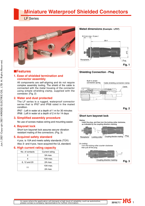
Mated dimensions (Example : LF07)
8.9 mm max. (3 pos.)
36.4
Receptacle
Plug
Fig. 1
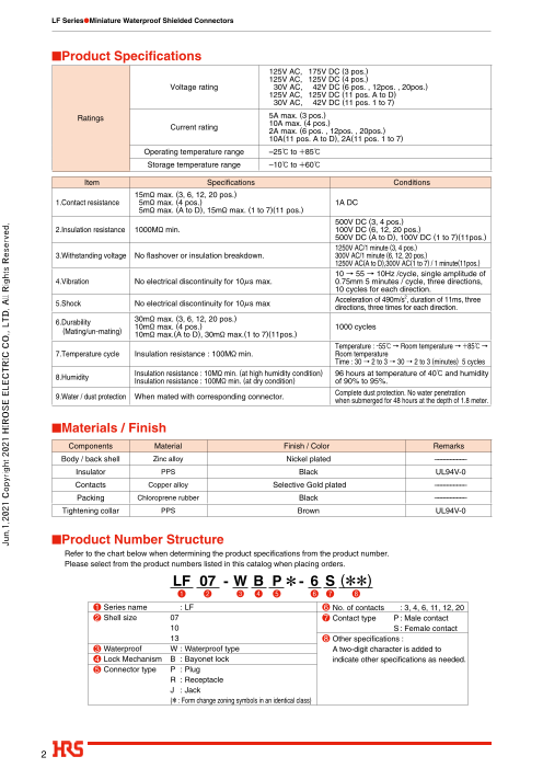
■Features Shielding Connection - Plug
1. Ease of shielded termination and
connector assembly
Built-in shield
All components are self-aligning and do not require connection spring Cable shielding connection clamp
complex assembly tooling. The shield of the cable is
Cable
connected with the metal housing of the connector
using simple shielding clamp, supplied with the
connector. (Fig. 2)
2. Water and dust protected
The LF series is a rugged, waterproof connector
series that is IP67 and IP68 rated in the mated
condition. Fig. 2
IP67 : Left in water at a depth of 1 m for 30 minutes
IP68 : Left in water at a depth of 2 m for 14 days
Short turn bayonet lock
3. Simplified assembly procedure
Mating:
No use of screws makes wiring and mounting easier. Insert the plug, and then turn the locking collar clockwise,
as indicated by the coupling direction marking.
4. Bayonet lock
2
Short turn bayonet lock assures secure vibration
resistant mating of the connectors. (Fig. 3) 1
5. Acquired safety standard Receptacle Locking collar Coupling direction marking Plug
4 pos. is 10A and meets safety standards (TÜV)
Also 3- and 4-pos. have acquired the UL standard. Un-mating:
Turn the locking collar counter-clockwise
6. High current rating capacity then pull off the plug.
No. of contacts Current rating 1
2
3 5A max.
4 10A max.
Coupling direction marking
6, 12 and 20 2A max. Fig. 3
10A max.
11
2A max.
In cases where the application will demand a high level of reliability, such as automotive,
please contact a company representative for further information. 2018.7④ 1
Jun.1.2021 Copyright 2021 HIROSE ELECTRIC CO., LTD. All Rights Reserved.
Ø13
Page2
LF Series●Miniature Waterproof Shielded Connectors
■Product Specifi cations
125V AC, 175V DC (3 pos.)
125V AC, 125V DC (4 pos.)
Voltage rating 30V AC, 42V DC (6 pos. , 12pos. , 20pos.)
125V AC, 125V DC (11 pos. A to D)
30V AC, 42V DC (11 pos. 1 to 7)
Ratings 5A max. (3 pos.)
10A max. (4 pos.)
Current rating
2A max. (6 pos. , 12pos. , 20pos.)
10A(11 pos. A to D), 2A(11 pos. 1 to 7)
Operating temperature range –25ç to +85ç
Storage temperature range –10ç to +60ç
Item Specifi cations Conditions
15mø max. (3, 6, 12, 20 pos.)
1.Contact resistance 5mø max. (4 pos.) 1A DC
5mø max. (A to D), 15mø max. (1 to 7)(11 pos.)
500V DC (3, 4 pos.)
2.Insulation resistance 1000Mø min. 100V DC (6, 12, 20 pos.)
500V DC (A to D), 100V DC (1 to 7)(11pos.)
1250V AC/1 minute (3, 4 pos.)
3.Withstanding voltage No fl ashover or insulation breakdown. 300V AC/1 minute (6, 12, 20 pos.)
1250V AC(A to D),300V AC(1 to 7) / 1 minute(11pos.)
10 → 55 → 10Hz /cycle, single amplitude of
4.Vibration No electrical discontinuity for 10µs max. 0.75mm 5 minutes / cycle, three directions,
10 cycles for each direction.
2
Acceleration of 490m/s , duration of 11ms, three
5.Shock No electrical discontinuity for 10µs max
directions, three times for each direction.
6.Durability6. 30mø max. (3, 6, 12, 20 pos.)
10mø max. (4 pos.) 1000 cycles(Mating/un-mating) 10mø max.(A to D), 30mø max.(1 to 7)(11pos.)
Temperature : -55ç → Room temperature → +85ç →
7.Temperature cycle Insulation resistance : 100Mø min. Room temperature
Time : 30 → 2 to 3 → 30 → 2 to 3 (minutes) 5 cycles
Insulation resistance : 10Mø min. (at high humidity condition) 96 hours at temperature of 40ç and humidity
8.Humidity
Insulation resistance : 100Mø min. (at dry condition) of 90% to 95%.
Complete dust protection. No water penetration
9.Water / dust protection When mated with corresponding connector.
when submerged for 48 hours at the depth of 1.8 meter.
■Materials / Finish
Components Material Finish / Color Remarks
Body / back shell Zinc alloy Nickel plated ––––––––––
Insulator PPS Black UL94V-0
Contacts Copper alloy Selective Gold plated ––––––––––
Packing Chloroprene rubber Black ––––––––––
Tightening collar PPS Brown UL94V-0
■Product Number Structure
Refer to the chart below when determining the product specifications from the product number.
Please select from the product numbers listed in this catalog when placing orders.
LF 07 - W B P * - 6 S (**)
❶ ❷ ❸ ❹ ❺ ❻ ❼ ❽
1 Series name : LF 6 No. of contacts : 3, 4, 6, 11, 12, 20
2 Shell size 07 7 Contact type P : Male contact
10 S : Female contact
13 8 Other specifications :
3 Waterproof W : Waterproof type A two-digit character is added to
4 Lock Mechanism B : Bayonet lock indicate other specifications as needed.
5 Connector type P : Plug
R : Receptacle
J : Jack
(* : Form change zoning symbols in an identical class)
2
Jun.1.2021 Copyright 2021 HIROSE ELECTRIC CO., LTD. All Rights Reserved.
Page3
LF Series●Miniature Waterproof Shielded Connectors
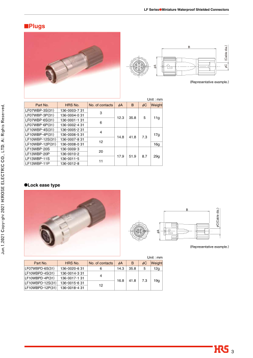
■Plugs
B
(Representative example.)
Unit : mm
Part No. HRS No. No. of contacts ØA B ØC Weight
LF07WBP-3S(31) 136-0003-7 31
3
LF07WBP-3P(31) 136-0004-0 31
12.3 35.8 5 11g
LF07WBP-6S(31) 136-0001-1 31
6
LF07WBP-6P(31) 136-0002-4 31
LF10WBP-4S(31) 136-0005-2 31
4
LF10WBP-4P(31) 136-0006-5 31 17g
14.8 41.8 7.3
LF10WBP-12S(31) 136-0007-8 31
12
LF10WBP-12P(31) 136-0008-0 31 16g
LF13WBP-20S 136-0009-3
20
LF13WBP-20P 136-0010-2
17.9 51.9 8.7 29g
LF13WBP-11S 136-0011-5
11
LF13WBP-11P 136-0012-8
●Lock ease type
B
(Representative example.)
Unit : mm
Part No. HRS No. No. of contacts ØA B ØC Weight
LF07WBPD-6S(31) 136-0020-6 31 6 14.3 35.8 5 12g
LF10WBPD-4S(31) 136-0014-3 31
4
LF10WBPD-4P(31) 136-0017-1 31
16.8 41.8 7.3 19g
LF10WBPD-12S(31) 136-0015-6 31
12
LF10WBPD-12P(31) 136-0018-4 31
3
Jun.1.2021 Copyright 2021 HIROSE ELECTRIC CO., LTD. All Rights Reserved.
ØA
ØA
ØC(Cable dia.)
ØC (Cable dia.)
Page4
LF Series●Miniature Waterproof Shielded Connectors
■Receptacles
●Front panel mount type・Solder Type
C
D
E
F(HEX)
(Representative example.)
Unit : mm
Part No. HRS No. No. of contacts ØA ØB C D ØC E F Weight
LF07WBR-3P 136-1003-2
3 16.55
LF07WBR-3S 136-1004-5
10.3 13 7.65 1M9∞0.75 11 4g
LF07WBR-6P 136-1001-7 15.05
6
LF07WBR-6S 136-1002-0 15.25
LF10WBR-4P 136-1005-8
4 19.05 6g
LF10WBR-4S 136-1006-0
12.8 15.3 7.75 M11∞0.75 13
LF10WBR-12P 136-1007-3 5g
12 17.25
LF10WBR-12S 136-1008-6 6g
LF13WBR-20P 136-1009-9 9g
20 17.25
LF13WBR-20S 136-1010-8 10g
15.9 18.3 7.75 M14∞0.75 17
LF13WBR-11P 136-1011-0 9g
11 19.05
LF13WBR-11S 136-1012-3 10g
●Front panel mount type・Through hole Type
C
D
E
F(HEX)
(Representative example.)
Unit : mm
Part No. HRS No. No. of contacts ØA ØB C D E F Weight
LF13WBR-20SD 136-1017-7 20 15.9 18.3 17.5 7.75 M14∞0.75 17 9g
4
Jun.1.2021 Copyright 2021 HIROSE ELECTRIC CO., LTD. All Rights Reserved.
ØB ØB
ØA ØA
Page5
LF Series●Miniature Waterproof Shielded Connectors
■Receptacles
●Rear panel mount type・Solder Type
D(HEX) C
E
(Representative example.)
Unit : mm
Part No. HRS No. No. of contacts ØA ØB C D E Weight
LF10WBRB-4P 136-1118-4 4 19.05
LF10WBRB-12P 136-1013-6 12.8 18.3 17 M14∞0.75 10g
12 17.25
LF10WBRB-12S 136-1014-9
LF13WBRB-20S 136-1018-0 20
15.9 21.5 19.25 20 M17∞0.75 16g
LF13WBRB-11S 136-1019-2 11
●Rear panel mount type ・ Through hole Type
D(HEX) C
E
(Representative example.)
Unit : mm
Part No. HRS No. No. of contacts ØA ØB C D E Weight
LF10WBRB-12PD 136-1015-1
12 12.8 18.3 17.5 17 M14∞0.75 9g
LF10WBRB-12SD 136-1016-4
■Jacks
C
(Representative example.)
Unit : mm
Part No. HRS No. No. of contacts ØA ØB C ØD Weight
LF07WBJ-3P 136-2003-8
3
LF07WBJ-3S 136-2004-0
10.3 11.5 36.3 5 11g
LF07WBJ-6P 136-2001-2
6
LF07WBJ-6S 136-2002-5
LF10WBJ-4P 136-2005-3
4
LF10WBJ-4S 136-2006-6
12.8 13.8 42.4 7.3 16g
LF10WBJ-12P 136-2007-9
12
LF10WBJ-12S 136-2008-1
LF13WBJ-20P 136-2009-4 29g
20
LF13WBJ-20S 136-2010-3 30g
15.9 16.9 52.4 8.7
LF13WBJ-11P 136-2011-6 29g
11
LF13WBJ-11S 136-2012-9 30g
5
Jun.1.2021 Copyright 2021 HIROSE ELECTRIC CO., LTD. All Rights Reserved.
ØB
ØA
ØA
ØA
ØB
ØB
ØD (Cable dia.)
Page6
LF Series●Miniature Waterproof Shielded Connectors
■CAP
●For Receptacles
B
(Representative example.)
Unit : mm
Part No. HRS No. Applicable connector ØA B Weight
LF07WBR-6P
LF07WBR-6S
LF07WBR-C 136-3008-7 12.3 4g
LF07WBR-3P
LF07WBR-3S
LF10WBR-4P
LF10WBR-4S
LF10WBR-12P
LF10WBR-12S
LF10WBR-C 136-3001-8 LF10WBRB-4P 14.8 5g
LF10WBRB-12P
8.8
LF10WBRB-12S
LF10WBRB-12PD
LF10WBRB-12SD
LF13WBR-20P
LF13WBR-20S
LF13WBR-11P
LF13WBR-C 136-3003-3 LF13WBR-11S 17.9 7g
LF13WBR-20SD
LF13WBRB-20S
LF13WBRB-11S
6
Jun.1.2021 Copyright 2021 HIROSE ELECTRIC CO., LTD. All Rights Reserved.
ØA
Page7
LF Series●Miniature Waterproof Shielded Connectors
BApplicable tools
Unit : mm
Description Part No. HRS No. LF series Applicable cable dia.
Manual cable HR10A-TC-02 150-0041-2 5 (Note)
clamp crimp LF-TC-01 150-0234-6 7.3 · 8.7
(Representative example.) Note : Applicable cable dia. is only 5mm for LF series.
BSolder termination fixture
(Representative example.) (Representative example.)
Part No. HRS No. Applicable connectors
LF07BP-T01 150-0232-0 LF07WBP-**
LF07BJ-T01 150-0233-3 LF07WBJ-**
LF10BP-T01 150-0235-9 LF10WBP-**
LF10BJ-T01 150-0236-1 LF10WBJ-**
LF13BP-T01 150-0237-4 LF13WBP-** Note : It is applicable regard less of given
LF13BJ-T01 150-0238-7 LF13WBJ-** alphabets or Numbers shown at *.
BPanel Cutout Unit : mm
Alignment guide
Shell size A B Weight
LF07WBR-** Ø9.05 8.1
LF10WBR-** Ø11.05 10.2
0.7 to 2
LF13WBR-**
Ø14.05 13.1
LF10WBRB-**
+0.05
B 0
LF13WBRB-** Ø17.05 16.1 0.7 to 4.8
BContact position arrangement and specifications
Shell size LF07 LF10 LF13
9 1
1
B C 2 3 4 5
6 1 4 8 10 2
Contact arrangement 3 1
1
5 2 A D
6 7 8 9 10
7 12 11 3 11 12 13 14 15
2 4 3 3 2 6 1
2 3 4 16 17 18 19
5 4 5 6 7 20
No. of contacts 3 6 4 12 11 20
4 7
Withstanding voltage 1250V AC 300V AC 1250V AC 300V AC AC300V
AC1250V AC300V
4 7
Current rating 5A 2A 10A 2A 2A
10A 2A
Insulation resistance 1000Mø
4 7
Contact resistance 15mø 5mø 15mø 15mø
5mø 15mø
4 7
Solder pot inner diameter 1.15mm 0.8mm 1.7mm 0.8mm 0.8mmØ1.7 Ø0.8
Note 1 : The contact configuration as viewed from the female contact connector mating side.
Note 2 : The ▼ symbol indicates polarizing key position.
Note 3 : Withstanding voltages are test voltage values.
7
Jun.1.2021 Copyright 2021 HIROSE ELECTRIC CO., LTD. All Rights Reserved.
.0
5
+0 0A
Page8
LF Series●Miniature Waterproof Shielded Connectors
□Termination and Assembly Instructions
The connectors are delivered with pre-assembed condition and the disassembly as shown No.1.
No. Illustration Operation
1 Solder termination fixture
Plug disassembly
1 Plug 1 Insert the plug into securely held solder
termination fixture as shown.
Fixture Part No. Applicable connector
Locking collar LF07BP-T01 LF07WBP-6S,6P,3S,3P
LF10BP-T01 LF10WBP-4S,4P,12S,12P
Insertion direction LF13BP-T01 LF13WBP-20S,20P,11S,11P
2 Body / insulator assembly
2 Loosen the backshell turning it counter
Backshell clockwise and remove it from the body/
insulator assembly.
Note
Note Vice fixed ban
When removing, assembling and wiring, be
Vice A
sure to use a solder termination fixture.
A Detail view Retaining ring Directly fixing the locking collar in place with
a vice etc.. could lead to damage,
Vice deformation or lacuna of retaining ring.
1 Solder termination fixture
Jack Disassembly
Jack 1 Insert the jack into the securely held solder
termination fixture as shown.
Fixture Part No. Applicable connector
LF07BJ-T01 LF07WBJ-6S,6P,3S,3P
Insertion direction LF10BJ-T01 LF10WBJ-4S,4P,12S,12P
LF13BJ-T01 LF13WBJ-20S,20P,11S,11P
Body / insulator assembly 2 Loosen the backshell turning it2
counterclockwise.
Backshell
Note
When removing, assembling and wiring, be
Note Vice fixed ban
sure to use a solder termination fixture.
Vice
Directly fixing the body in place with a vice
etc.. could lead to damage or deformation.
Vice
Backshell Connector Assembly
2 1 1 Apply a coating of Loctite 7649
(Manufactured by Henkel Japan, Ltd,) primer
to the threaded sections of the backshell and
the tightening collar. Completely dry the
coated surfaces.
Threaded section Threaded section
Notes
(1) Drying time at room temperature is
approximately 30 to 70 seconds.
(2) Ensure sufficient ventilation of the area at
time of drying.
(3) Take necessary steps to protect the coated
Tightening collar surfaces from contamination.
Backshell Strain relief collar Thread the tightening collar, strain relief collar,
2 Tightening collar 2
seal bushing and the backshell over the cable
as illustrated.
Note
Threading the components may not be
Cable preparation end Gasket Cable possible after the cable-end finishing process.
8
Jun.1.2021 Copyright 2021 HIROSE ELECTRIC CO., LTD. All Rights Reserved.
Page9
LF Series●Miniature Waterproof Shielded Connectors
No. Illustration Operation
Cable preparation
3 1 Stripping dimensions 1 Strip the cable’s outer jacket to the dimensions
A Cable outer jacket illustrated in the table 1.
Table 1. Stripping Dimensions Notes
No. of Conductors A mm
(1) Exercise caution not to damage the shielding
3
8 to 9
6 mesh.
4 13 to 14 Any damage to the cable’s outer jacket may
Shielding mesh (2)12 14 to 15
affect the waterproof performance of the
22 to 23 (No.A to D)
11
23 to 24 (No.1 to 7) assembled connector.
20 23 to 24
Shielding mesh Cable outer jacket
Wires 2 Fold back the shielding mesh over the cable’s2
outer jacket assuring that it is uniform on its
diameter.
Shielding mesh
4 to 5mm
(Folded back)
Wires Cable outer jacket
Stripping dimensions
3 Strip the wires to the dimensions illustrated in
3 Cable outer jacket
the Table 2.
Table 2. Stripping Dimensions
B Wires NoteNo. of Conductors B mm
3 2.5±0.5 When stripping the wires exercise caution not
6 2±0.5 to damage it’s insulation, folded over
4 3±0.5 shielding mesh or cable’s outer jacket.
12 2±0.5
3±0.5 (No.A to D) It may cause deffects in insulation,
11
2±0.5 (No.1 to 7) conduction, and waterproof performance.
Conductors 20 2±0.5
4 Soldering
1 Soldering conditions
Soldering iron tip temperature: 350±10ç
Soldering time: within 5 sec.
Notes
(1) Assure that the solder compound is
sufficiently melted on the soldering iron tip.
(2) When applying, make sure that the solder will
flow correctly at all the contact surfaces
between the conductor and the contact.
C 2 – 1 6, 12, 11(No.1 to 7), 20 Conductors2 – 1 Wire
Table 3 Heat shrink tubing Dimensions
(1) Place a heat-shrink tubing (inside diameter of
Insulator No. of No. of contacts C mm 1.1 mm min.) over every other wire.
Conductors
Contact Perform the soldering of the contact and the
6 1 to 6 4
(2) conductor, with the wire’s insulation touching
1 to 9 4
12 the contact as shown.
10 to 12 6 After soldering, slide the heat shrink tubing
1 to 4 6
Heat-shrink tubing 11 (3) over the soldered joint and shrink it. The 5 to 7 4 tubing should touch the insulator as shown.
1 to 5,16 to 20 4
20 6 to 15 6
Insulator
Insulator wall – 2 3, 4, 11(No.A to D) Conductors
2 2– 2
(1) Perform the soldering of the contact and the
conductor, with the wire’s insulation touching
Insulator Contact Contact Wire insulation the contact as illustrated.
Insulator wall (2) When soldering, to maintain the insulation
between adjacent contacts. Make sure that
the wire’s insulation remains below the edge
Wire insulation of the insulator’s wall 0.5 mm min., as
illustrated.
Solder 0.5 mm min.
9
Jun.1.2021 Copyright 2021 HIROSE ELECTRIC CO., LTD. All Rights Reserved.
Page10
LF Series●Miniature Waterproof Shielded Connectors
No. Illustration Operation
4 3 D Cable outer jacket 3 After the soldering, keep a distance of D
between the contact end and the cable’s
Table 4. Wire Dimensions
outer jacket as illustrated.
No. of Conductors D mm
Note
3
6 to 7
6 The distance of D is required in order to
Shielding mesh 4 10 to 11 assure correct assembly of the backshell.
(Folded back) 12 13 to 14
11
18 to 19
20
Solder termination fixture Crimping of the Shielding Clamp
5 1
Body / insulator assembly 1 After completion of the soldering operations
carefully remove (holding on the locking collar)
the body/insulator assembly from the solder
termination fixture.
Note
Exercise caution not to damage or deform the
Soldered joints solder joints.
2 Wrap the folded over shielding mesh with 5 to
2 Cable outer jacket
6mm wide copper tape to assure that it will
Cable outer jacket
Wires Copper tape
not become loose.
Apply the copper tape so that the shielding
mesh does not protrude from under it.
Note
After wrapping the copper tape, the tape
Shielding mesh 5 to 6mm
Copper tape should overlap itself by 2mm max.
3 Insert the “U” shaped shielding clamp over the
3
copper tape as shown on the illustration.
Cable outer jacket
Copper tape It is critical that the overlap of the copper tape
Ground clamp 1±0.5mm is located inside the shielding clamp as shownCable outer jacket
on the illustration.
Copper tape
Note
When the end of the copper tape wrapping is
positioned at the open side of the ground
Wires Shielding clamp fitting, the end portion of the copper tape
Shielding mesh wrapping will no longer be covered by the
ground fitting when the ground fitting is
Overlap of the copper tape crimped.
4 Using commercially available pliers bend the
4
open ends of the shielding clamp as illustrated,
Commercially assuring that it stays in place. The dimension
available pliers of E. between opposing edges of the shielding
clamp is necessary to assure correct final
E crimp.
Table 5
Shell size E
LF07 5mm max.
LF10
Shielding clamp 7mm max.LF13
Overlap of the copper tape
10
Jun.1.2021 Copyright 2021 HIROSE ELECTRIC CO., LTD. All Rights Reserved.
2 mm
max.
Page11
LF Series●Miniature Waterproof Shielded Connectors
No. Illustration Operation
Crimping tool 5 Both sides of the shielding clamp must be
5 5 Forming cavity placed in the forming cavity of the tool
(as shown on the illustration) and crimped
over the cable by closing the tool completely.
Applicable Shielding clamp
Crimping tool Forming cavity cable diameter
diameter after crimping
5.3 5mm 5.3mm to5.5mm
HR10A-TC-02
7.0 ––– –––
7.9mm to
7.9 7.3mm 8.1mm
LF-TC-01
9.1 8.7mm 9.1mm to9.3mm
Connector Assembly
1 , 2 Locktite area
6 Wiring side 1 to 2 threaded portion 1 Place the body/insulator assembly in the
applicable solder termination fixture.
For plug assembly
Fixture Part No. Applicable connector
LF07BP-T01 LF07WBP-6S,6P,3S,3P
LF10BP-T01 LF10WBP-4S,4P,12S,12P
LF13BP-T01 LF13WBP-20S,20P,11S,11P
For jack assembly
Body/insulator assembly Fixture Part No. Applicable connector
LF07BJ-T01 LF07WBJ-6S,6P,3S,3P
Threaded section
Backshell LF10BJ-T01 LF10WBJ-4S,4P,12S,12P
LF13BJ-T01 LF13WBJ-20S,20P,11S,11P
2 Coat the thread section of the body/insulator
assembly with Loctite 263 compound
(manufactured by Henkel Japan, Ltd.) or
equivalent, tightening it with a torque
specified in the table 6.
Notes
Wrench width : D (1) The applied loctite should not protrude out further
than the wiring side 1 to 2 threaded section. If it
Table 6 (Recommend tightening torgue) does, it may affect waterproof performance and
Shell size Tightening torque Wrench width locking. Please remove any protruding loctite
LF07 1N·m to 1.5N·m 10mm with a cloth or cotton swab. etc.
LF10 1N·m to 1.5N·m 13mm (2) It is critical that the cable itself will not turn or
LF13 1.5N·m to 2N·m 16mm twist during this operation.
It may cause breakage at the soldered area.
3 Slide forward the gasket and insert it in
3 , 4
Gasket the backshell until fully seated.
Strain relief collar 4 Slide forward the strain relief collar and insert
it in the backshell, making sure that the
opposing protrusions fit inside the
corresponding grooves, as shown on the
illustration.
Note
Groove Protrusion It is critical that the protrusions are inside the
Tightening collar corresponding grooves.
It may cause breakage, when a tightening collar is assembled.
5 5 Verify that the Locktite 7649 primer
Threaded section
(or equivalent) on the threaded sections of the
Tightening collar
backshell and tightening collar are dry.
Apply the Locktite 263 compound to the
tightening collar’s threaded section and attach
it to the backshell.
11
Jun.1.2021 Copyright 2021 HIROSE ELECTRIC CO., LTD. All Rights Reserved.
5.3
7.0
Page12
LF Series●Miniature Waterproof Shielded Connectors
No. Illustration Operation
6 6 Remove the connector from the solder6 Tightening collar termination fixture, holding it by the locking
collar. Do not pull on the cable.
It may cause breakage.
Recommended tightening torgue
Wrench width
Shell size Tightening torque Wrench width
LF07 0.8N·m to 1N·m 10mm
LF10 0.7N·m to 1N·m 14mm
LF13 1 N·m to 1.5 N·m 16mm
Confirmation of Waterproof Performance
7
After connector assembly procedure is completed,
compress air in to the connector from the mating
side under 17.6 kPa for 30 seconds check that no
air leaks out of the connector.
□Cable Specifications (Reference)
No. of contact 3 pos. 4 pos. 6 pos. 12 pos. 20 pos. 11 pos.
Material Tin plated soft copper wire
Size (mm) Ø0.18 Ø0.26 Ø0.16 Ø0.16 Ø0.16 Ø0.26 Ø0.16
Construction 20 /Ø0.18 mm dia. 20 /Ø0.26 mm dia. 7 /Ø0.16 mm dia. 7 /Ø0.16 mm dia. 7 /Ø0.16 mm dia. 26 /Ø0.26 mm dia. 7 /Ø0.16 mm dia.
Size (AWG) 20 AWG 16 AWG 26 AWG 26 AWG 26 AWG 16 AWG 26 AWG
Sectional area 0.5 1.25 0.14 0.14 0.14 1.25 0.14
Diameter (mm) Ø0.98 Ø1.5 Ø0.48 Ø0.48 Ø0.48 Ø1.5 Ø0.48
Diameter (mm) Ø1.5 (Standard) Ø2.1 (Standard) Ø0.88 (Standard) Ø0.9 (Standard) Ø0.9 (Standard) Ø2.1 (Standard) Ø0.95 (Standard)
Thickness (mm) 0.26 0.3 0.2 0.21 0.21 0.3 0.24
Material Tin plated soft copper wire
Density 85% 80% or more 85% 80% or more 80% or more 80% or more
Diameter (mm) Ø3.6 Ø5.5 Ø3.4 Ø4.2 Ø5.1 Ø6.7
Diameter (mm)
Ø5±0.2 Ø7.3±0.2 Ø5±0.2 Ø7.3±0.2 Ø8.7±0.2 Ø8.7±0.2
Remarks : The cable satisfies required specifications for UL specification.
Notes : The cable pull and twisting strength, waterproof tightness and other characteristics may differ, depending on the cable structure,
please confirm before the use.
® 2-6-3,Nakagawa Chuoh,Tsuzuki-Ku,Yokohama-Shi 224-8540,JAPAN
TEL: +81-45-620-3526 Fax: +81-45-591-3726
http://www.hirose.com
http://www.hirose-connectors.com
The characteristics and the specifications contained herein are for reference purpose. Please refer to the latest customer drawings prior to use.
12 The contents of this catalog are current as of date of 07/2018. Contents are subject to change without notice for the purpose of improvements.
Jun.1.2021 Copyright 2021 HIROSE ELECTRIC CO., LTD. All Rights Reserved.
Jacket Shield Insulator Conductor