


段取り替え無しに、幅広い径のクランプが可能
●コンパクト(短くて、頑丈な)構造
●全クランプ領域における、高い芯出し精度と繰り返し精度
●クランプ圧力を変えても精度劣化が無い
●集中潤滑
◆詳細はカタログをダウンロードしてご覧下さい。
このカタログについて
| ドキュメント名 | 細軸部品のより効率的な旋削加工 自動芯出し振止装置 |
|---|---|
| ドキュメント種別 | 製品カタログ |
| 登録カテゴリ | |
| 取り扱い企業 | 竹田商事株式会社 (この企業の取り扱いカタログ一覧) |
この企業の関連カタログ


このカタログの内容
Page1
www.roehm.biz
チャッキングツール – Chucking tools
自動芯出し振止装置
Self-centering steady rests
Page2
自動芯出し振止装置
細軸部品のより効率的な旋削加工
Self-centering stedy rests
to more efficient turning of slender shafts
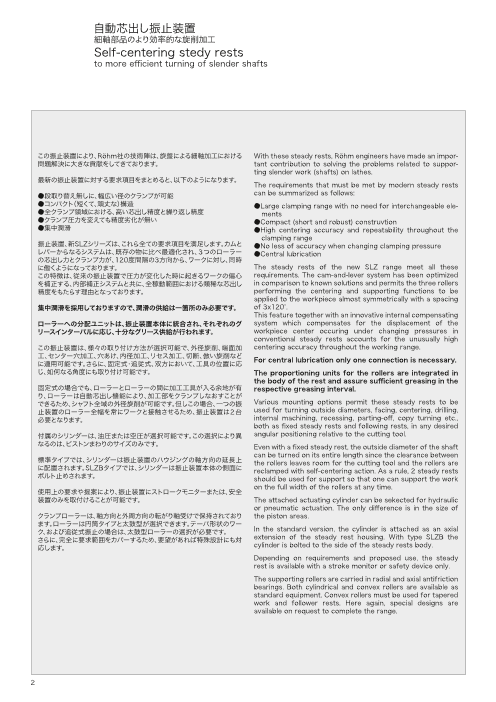
この振止装置により、Röhm社の技術陣は、旋盤による細軸加工における With these steady rests, Röhm engineers have made an impor-
問題解決に大きな貢献をしてきております。 tant contribution to solving the problems related to suppor-
ting slender work (shafts) on lathes.
最新の振止装置に対する要求項目をまとめると、以下のようになります。 The requirements that must be met by modern steady rests
●段取り替え無しに、幅広い径のクランプが可能 can be summarized as follows:
●コンパクト(短くて、頑丈な)構造 ●Large clamping range with no need for interchangeable ele-
●全クランプ領域における、高い芯出し精度と繰り返し精度 ments
●クランプ圧力を変えても精度劣化が無い ●Compact (short and robust) construvtion
●集中潤滑 ●High centering accuracy and repeatability throughout the
clamping range
振止装置、新SLZシリーズは、これら全ての要求項目を満足します。カムと ●No less of accuracy when changing clamping pressure
レバーからなるシステムは、既存の物に比べ最適化され、3つのローラー ●Central lubrication
の芯出し力とクランプ力が、120度間隔の3方向から、ワークに対し、同時
に働くようになっております。 The steady rests of the new SLZ range meet all these
この特徴は、従来の振止装置で圧力が変化した時に起きるワークの偏心 requirements. The cam-and-lever system has been optimized
を補正する、内部補正システムと共に、全稼動範囲における類稀な芯出し in comparison to known solutions and permits the three rollers
精度をもたらす理由となっております。 performing the centering and supporting functions to be
applied to the workpiece almost symmetrically with a spacing
集中潤滑を採用しておりますので、潤滑の供給は一箇所のみ必要です。 of 3x120°.
This feature together with an innovative internal compensating
ローラーへの分配ユニットは、振止装置本体に統合され、それぞれのグ system which compensates for the displacement of the
リースインターバルに応じ、十分なグリース供給が行われます。 workpiece center occuring under changing pressures in
conventional steady rests accounts for the unusually high
この振止装置は、様々の取り付け方法が選択可能で、外径旋削、端面加 centering accuracy throughout the working range.
工、センター穴加工、穴あけ、内径加工、リセス加工、切断、倣い旋削など
に適用可能です。さらに、固定式・追従式、双方において、工具の位置に応 For central lubrication only one connection is necessary.
じ、如何なる角度にも取り付け可能です。 The proportioning units for the rollers are integrated in
the body of the rest and assure sufficient greasing in the
固定式の場合でも、ローラーとローラーの間に加工工具が入る余地が有 respective greasing interval.
り、ローラーは自動芯出し機能により、加工部をクランプしなおすことが
できるため、シャフト全域の外径旋削が可能です。但しこの場合、一つの振 Various mounting options permit these steady rests to be
止装置のローラー全幅を常にワークと接触させるため、振止装置は2台 used for turning outside diameters, facing, centering, drilling,
必要となります。 internal machining, recessing, parting-off, copy turning etc.,
both as fixed steady rests and following rests, in any desired
付属のシリンダーは、油圧または空圧が選択可能です。この選択により異 angular positioning relative to the cutting tool.
なるのは、ピストンまわりのサイズのみです。 Even with a fixed steady rest, the outside diameter of the shaft
標準タイプでは、シリンダーは振止装置のハウジングの軸方向の延長上 can be turned on its entire length since the clearance between
に配置されます。SLZBタイプでは、シリンダーは振止装置本体の側面に the rollers leaves room for the cutting tool and the rollers are
ボルト止めされます。 reclamped with self-centering action. As a rule, 2 steady rests should be used for support so that one can support the work
使用上の要求や提案により、振止装置にストロークモニターまたは、安全 on the full width of the rollers at any time.
装置のみを取付けることが可能です。 The attached actuating cylinder can be sekected for hydraulic
or pneumatic actuation. The only difference is in the size of
クランプローラーは、軸方向と外周方向の転がり軸受けで保持されており the piston areas.
ます。ローラーは円筒タイプと太鼓型が選択できます。テーパ形状のワー
ク、および追従式振止の場合は、太鼓型ローラーの選択が必要です。 In the standard version, the cylinder is attached as an axial
さらに、完全に要求範囲をカバーするため、要望があれば特殊設計にも対 extension of the steady rest housing. With type SLZB the
応します。 cylinder is bolted to the side of the steady rests body.
Depending on requirements and proposed use, the steady
rest is available with a stroke monitor or safety device only.
The supporting rollers are carried in radial and axial antifriction
bearings. Both cylindrical and convex rollers are available as
standard equipment. Convex rollers must be used for tapered
work and follower rests. Here again, special designs are
available on request to complete the range.
2
Page3
自動芯出し振止装置 - 概要
Self-centering stedy rests - overview
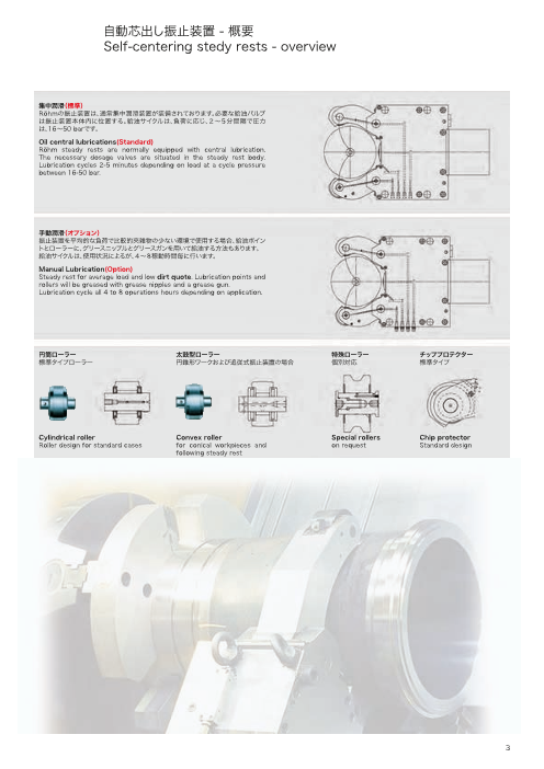
集中潤滑(標準)
Röhmの振止装置は、通常集中潤滑装置が装備されております。必要な給油バルブ
は振止装置本体内に位置する。給油サイクルは、負荷に応じ、2〜5分間隔で圧力
は、16〜50 barです。
Oil central lubrications(Standard)
Röhm steady rests are normally equipped with central lubrication.
The necessary dosage valves are situated in the steady rest body.
Lubrication cycles 2-5 minutes depending on load at a cycle pressure
between 16-50 bar.
手動潤滑(オプション)
振止装置を平均的な負荷で比較的夾雑物の少ない環境で使用する場合、給油ポイン
トとローラーに、グリースニップルとグリースガンを用いて給油する方法もあります。
給油サイクルは、使用状況によるが、4〜8稼動時間毎に行います。
Manual Lubrication(Option)
Steady rest for average load and low dirt quote. Lubrication points and
rollers will be greased with grease nipples and a grease gun.
Lubrication cycle all 4 to 8 operations hours depending on application.
円筒ローラー 太鼓型ローラー 特殊ローラー チッププロテクター
標準タイプローラー 円錐形ワークおよび追従式振止装置の場合 個別対応 標準タイプ
Cylindrical roller Convex roller Special rollers Chip protector
Roller design for standard cases for conical workpieces and on request Standard design
following steady rest
3
Page4
自動芯出し振止装置、油圧または空圧制御
Self-centering stedy rests, oil or air operated
SLZC 超小型デザイン
最小取付けエリアに対応
extremely compact design,
developed for minimum mounting dimensions
15ページ/Page 15
SLZK クランクシャフト加工用薄型クランプアーム
with slim clamping arms for machining crankshafts
16ページ/Page 16
SL 広範囲なクランプ径に対応、アーム交換式
wide clamping range with interchangeable clamping arms
24-25ページ/Page 24-25
SLB 広範囲なクランプ径に対応、アーム交換式、側面シリンダータイプ
wide clamping range with interchangeable clamping arms
with side mounted cylinder
26-27ページ/Page 26-27
4
Page5
自動芯出し振止装置、油圧または空圧制御
Self-centering stedy rests, oil or air operated
最適なワーク保持
Optimal support
Roehm振止装置の特徴
高い繰り返し精度、 高剛性、 取付け容易、小
型、 エアーパージによる夾雑物進入防止、ストロ
ーク調整、 集中潤滑
High repeatability, high stiffness, easy
mounting, small dimensions, air purge to
prevent dirt penetration, stroke control and
central lubrication are features highlighting
the Röhm steady rests.
SLZ シリンダー取付けタイプ
with mounted cylinder
6-7ページ/Page 6-7
SLZB 側面シリンダータイプ
with side mounted cylinder
8-9ページ/Page 8-9
SLZW片アーム開閉量拡大タイプ
extra opening of one arm
12-13ページ/Page 12-13
SLZR 4軸旋盤タレット取付けタイプ
for turrets on four axis lathes
17ページ/Page 17
SLZV 細軸研削用、X-Y軸方向微調整可能
steady rest for grinding with fine adjutment of
X - and Y - axis for the machining of slim shafts
34-38ページ/Page 34-38
5
Page6
自動芯出し振止装置 SLZ - スタンダードシリーズ
Self-centering stedy rests SLZ - Standard series
A
S4
P1
P C E H1SP ZS S3
R
d3
φG
K2 T
L D
ZS = M 10 x 1 L1
集中潤滑用コネクション
最小17 - 最大50 bar B G 1/4“ アンクランプ
Connection for ZS G 1/4“ Unclamping
central lubrication,
Min. 17 – Max. 50 bar
SP = G 1/8“
エアーパージコネクション
最小2 - 最大4 bar
Air purge connection φO SP G 1/4“ クランプ
Min. 2 – Max. 4 bar G 1/4“ Clamping
型式 Typ SLZ SLZ SLZ SLZ SLZ SLZ SLZ SLZ 047 08105 1152 1517 40200 325 50315 95360
d1 4 8 12 15 40 35 50 95
d2 70 105 152 170 200 250 315 360
d3 70 105 161 170 200 250 315 360
A 206 279.5 431.5 439.5 458.5 617.5 699 730.5
B 137 197 306 314 333 451 521.5 553
C 51 70 115 123 138 146 203 234.5
D 69 82.5 125.5 125.5 125.5 166.5 177.5 177.5
E 64 85 135 135 135 240 270 270
F 118 170 262 262 262 365 400 400
G 11 14 18 18 18 23 23 23
H 132 190 290 290 290 400 440 440
L 102 143 223 223 223 331.5 361 361
L1 115.5 164 251 251 251 364 406 406
K 54 58 85 85 85 110 145 145
M 20 31 48 48 48 60 75 75
N 11.5/9 20.5/19 30/25 30/25 30/25 40/35 45/40 45/40
O 19 35 47 47 47 52 60 60
P / / 9.5 9.5 9.5 13 21.5 21.5
P1 / / 34 34 34 12.5 12.5 12.5
P2 / / 121 121 121 160 160/175 160/175
R 48.6 74.5 122 130 143.5 183 209 242
S1 8 9,5 / / / / / /
S2 23 33 / / / / / /
S3 10 28 / / / / / /
S4 34.5 28 / / / / / /
K1 / 61.5 85 85 85 98 150 141
K2 / 30 42.5 42.5 42.5 55 59.5 59.5
e 60 68 98 98 98 124 142 142
e1 87 92 145 145 145 156 156 156
d 40 50 80 80 80 100 100 100
T / / / / / 45 31.5 31.5
T1 / / / / / 30° 30° 30°
R1 121 190 281 296.5 320 394 483 534
重量 – Weight kg 7 14.5 47 47 48 115 185 190
6
K1 P2
H
K
M R1
φd2
N φd1
S2
F
S1
e φd
e1
T1
Page7
自動芯出し振止装置 SLZ - スタンダードシリーズ
Self-centering stedy rests SLZ - Standard series
自動芯出し振止装置 SLZ – Steady rests SLZ
振止装置型式 – Steady rest クランプ領域 – Clamping ranges
SLZ 047 4 – 70
SLZ 08105 8 – 105
SLZ 1152 12 – 152
SLZ 1517 15 – 170
SLZ 40200 40 – 200
SLZ 325 35 – 250
SLZ 50315 50 – 315
SLZ 95360 95 – 360
0 50 100 150 200 250 300 350 400 450
クランプ領域 – Clamping ranges 型式 Typ SLZ SLZ SLZ SLZ SLZ SLZ SLZ SLZ 047 08105 1152 1517 40200 325 50315 95360
最大クランプ領域 - チッププロテクション無し
Max. clamping range - without chip protection 4-70 8-105 11-152 15-170 40-200 35-250 50-315 95-360
クランプ領域 - チッププロテクション有り
Clamping range - with chip protection 15-62 16-101 22-140 25-158 40-195 40-240 50-305 95-355
最大径方向クランプ領域 – d3 -
Max. radial clamping range – d3 - 70 105 161 170 200 250 315 360
集中潤滑付き
チッププロテクション付き RZ Id.-Nr. 685751 685755 685763 685771 1685600 685779 685787 1685604
With central lubrication
with chip protectors RB Id.-Nr. 685752 685756 685764 685772 1685601 685780 685789 1685605
集中潤滑付き
チッププロテクション無し RZ Id.-Nr. 685753 685757 685765 685773 1685602 685781 685790 1685606
With central lubrication
without chip protectors RB Id.-Nr. 685754 685758 685766 685774 1685603 685782 685791 1685607
クランプ力 / シリンダータイプ – Clamping forces / cylinder
シリンダー - φ
Cylinder - φ C40 C50 C80 C80 C80 C100 C100 C100
シリンダー表面積 - cm2
Cylinder surface area - cm2 12.5 19.6 50 50 50 78.5 78.5 78.5
最大使用圧力(bar)
Max. operating pressure in bar 25 53 62 68 40 57 80 58
使用圧力(bar)
Operating pressure in bar 5-20 6-30 6-40 6-44 6-25 8-42 8-58 8-40
ローラー1個当りの最大クランプ力 daN
Clamping force per roller at max. operating pressure daN 83 196 650 650 416 1100 1400 1046
ローラー1個当りの許容クランプ力 daN
Max. permissible clamping force per roller daN 104 350 1000 1000 667 1500 2000 1500
20bar時のローラー1個当りのクランプ力 daN
Clamping force per roller at 20 bar daN 83 130 323 280 280 520 520 500
全クランプ領域における芯出し精度 mm*
Centering accuracy over the entire clamping range mm* 0.02 0.02 0.04 0.04 0.04 0.05 0.06 0.06
同一径、同一クランプ力における芯出し繰り返し精度 mm
Repeat accuracy for the same clamping φ at the same operating pressure mm 0.005 0.005 0.005 0.005 0.005 0.005 0.01 0.01
ローラー最大周速 m/min
Max. roller peripheral speed m/min 800 800 725 725 725 715 700 700
ローラー1個当りの1/2最大クランプ力時の最大周速
Max. roller peripheral speed at half the max. clamping force per roller 900 950 875 875 875 860 850 850
使用圧20-70%変化(クランプ力一定)時のワーク中心の変位量(mm)
補正機能付き
Displacement of the geometrical workpiece center in the event of a 20-
70% change in the operating pressure (at constant clamping force) in 0.02 0.02 0.03 0.03 0.03 0.03 0.03 0.03
mm
Compensating system on request
* 圧力およびクランプ力一定
* at constant pressure and clamping force
7
Page8
自動芯出し振止装置 SLZB - 側面シリンダータイプ
Self-centering stedy rests SLZB - with side mounted cylinder
P1 A
P S4
SP ZS C E
g S3
D
R
φG
K2 L
T
L1
ZS = M 10 x 1 B
集中潤滑用コネクション ZS
最小17 - 最大50 bar
Connection for
central lubrication, G 1/4“ アンクランプ
Min. 17 – Max. 50 bar G 1/4“ Unclamping
SP = G 1/8“
エアーパージコネクション
最小2 - 最大4 bar φO
Air purge connection SP G 1/4“ クランプ
Min. 2 – Max. 4 bar G 1/4“ Clamping
型式 Typ SLZB SLZB SLZB SLZB SLZB SLZB SLZB08105 1152 1517 40200 325 50315 95360
d1 8 11 15 40 35 50 95
d2 105 152 170 200 250 315 360
d3 105 161 170 200 250 315 360
A 228 341 349 368 489 566.5 598
B 197 306 314 333 451 521.5 553
C 70 115 123 138 146 203 234.5
D 31 35 35 35 38 45 45
E 85 135 135 135 240 270 270
F 170 262 262 262 365 400 400
G 14 18 18 18 23 23 23
H 190 290 290 280 400 440 440
L 143 223 223 223 331.5 361 361
L1 164 251 251 251 364 406 406
K 58 85 85 85 110 145 145
M 31 48 48 48 60 75 75
N 20.5/19 30/25 30/25 30/25 40/35 45/40 45/40
O 35 47 47 47 52 60 60
P / 9.5 9.5 9.5 13 21.5 21.5
P1 / 34 34 34 12.5 12.5 12.5
P2 / 121 121 121 160 160/175 160/175
R 74.5 122 130 143.5 183 209 242
S1 9.5 / / / / / /
S2 33 / / / / / /
S3 28 / / / / / /
S4 28 / / / / / /
K1 61.5 85 85 85 98 150 141
K2 30 42.5 42.5 42.5 55 59.5 59.5
a 95 140 140 140 180/136 180/136 180/136
b 53 100 100 100 106/119 101/114 101/114
d 50 80 80 80 100 100 100
g 69 102 110 135 180 182.5 214
T / / / / 45 31.5 31.5
T1 / / / / 30° 30° 30°
R1 190 281 296.5 320 394 483 534
重量 – Weight kg 14.5 51 51 52 134 194 199
8
K1 P2
H
K R1
M φd3
φd2
N φd1
b
S2
S1
φd
a
F
T1
Page9
自動芯出し振止装置 SLZB - 側面シリンダータイプ
Self-centering stedy rests SLZB - with side mounted cylinder
自動芯出し振止装置SLZB – Steady rests SLZB
振止装置型式 – Steady rest クランプ領域 – Clamping ranges
SLZB 08105 8 – 105
SLZB 1152 12 – 152
SLZB 1517 15 – 170
SLZB 40200 40 – 200
SLZB 325 35 – 250
SLZB 50315 50 – 315
SLZB 95360 95 – 360
0 50 100 150 200 250 300 350 400 450
クランプ領域 – Clamping ranges 型式 Typ SLZB SLZB SLZB SLZB SLZB SLZB SLZB 08105 1152 1517 40200 325 50315 95360
最大クランプ領域 - チッププロテクション無し
Max. clamping range - without chip protection 8-105 11-152 15-170 40-200 35-250 50-315 95-360
クランプ領域 - チッププロテクション有り
Clamping range - with chip protection 16-101 22-140 25-158 40-195 40-240 50-305 95-355
最大径方向クランプ領域 – d3 -
Max. radial clamping range – d3 - 105 161 170 200 250 315 360
集中潤滑付き
チッププロテクション付き RZ Id.-Nr. 685792 685796 685748 1685608 685744 685740 1685612
With central lubrication
with chip protectors RB Id.-Nr. 685793 685797 685747 1685609 685743 685739 1685613
集中潤滑付き
チッププロテクション無し RZ Id.-Nr. 685794 685750 685746 1685610 685742 685738 1685614
With central lubrication
without chip protectors RB Id.-Nr. 685795 685749 685745 1685611 685741 685737 1685615
クランプ力 / シリンダータイプ – Clamping forces / cylinder
シリンダー - φ
Cylinder - φ C50 C80 C80 C80 C100 C100 C100
シリンダー表面積 cm2
Cylinder surface area cm2 19.6 50 50 50 78.5 78.5 78.5
最大使用圧力(bar)
Max. operating pressure in bar 53 62 68 40 57 80 58
使用圧力(bar)
Operating pressure in bar 8-30 8-40 8-44 8-25 8-42 8-58 4-40
ローラー1個当りの最大クランプ力 daN
Clamping force per roller at max. operating pressure daN 196 650 650 416 1100 1400 1046
ローラー1個当りの許容クランプ力 daN
Max. permissible clamping force per roller daN 350 1000 1000 667 1500 2000 1500
20bar時のローラー1個当りのクランプ力 daN
Clamping force per roller at 20 bar daN 130 323 280 280 520 520 500
全クランプ領域における芯出し精度 mm*
Centering accuracy over the entire clamping range mm* 0.02 0.04 0.04 0.04 0.05 0.06 0.06
同一径、同一クランプ力における芯出し繰り返し精度 mm
Repeat accuracy for the same clamping φ at the same operating pressure mm 0.005 0.005 0.005 0.005 0.005 0.01 0.01
ローラー最大周速 m/min
Max. roller peripheral speed m/min 800 725 725 725 715 700 700
使用圧20-70%変化(クランプ力一定)時のワーク中心の変位量(mm)
補正機能付き
Displacement of the geometrical workpiece center in the event of a 20-
70% change in the operating pressure (at constant clamping force) in 0.02 0.03 0.03 0.03 0.03 0.03 0.03
mm
Compensating system on request
ローラー1個当りの1/2最大クランプ力時の最大周速
Max. roller peripheral speed at half the max. clamping force per roller 950 875 875 875 860 850 850
* 圧力およびクランプ力一定
* at constant pressure and clamping force
9
Page10
自動芯出し振止装置 SLZ - 高負荷用ヘビーデザイン
Self-centering stedy rests SLZ - heavy design for high loads
R 1/8“ 振止装置、ミドルローラー用
エアーパージコネクション
R 1/8“ Air purge connection for steady
A rest and for middle roller
B
セーフティーバルブ
Safety valve
M10x1 集中潤滑用コネクション
M10x1 Connection for
central lubrication
φO
型式 Typ SLZ SLZ SLZ SLZ SLZ437 5040 1546 1060 3580
d1 40 50 150 100 350
d2 370 400 460 600 800
A 1086 1100 1110 1465 1810
B 762 800 800 1105 1340
H 730 730 730 1020 1270
K 170 170 170 270 440
M 90 90 90 170 240
N 60/50 60/50 60/50 104/95 150/138
O 80 80 80 160 220
e1 240 240 240 280 320
e 150 150 150 260 370
d 120 120 120 150 180
重量 – Weight kg 490 500 570 2000 4000
10
H
M
φd2
N
φd1
K
e d
e1
Page11
自動芯出し振止装置 SLZ - 高負荷用ヘビーデザイン
Self-centering stedy rests SLZ - heavy design for high loads
自動芯出し振止装置SLZ ヘビーデザイン – Steady rests SLZ heavy
振止装置型式 – Steady rest クランプ領域 – Clamping ranges
SLZ 437 40 – 375
SLZ 5040 50 – 400
SLZ 1546 150 – 460
SLZ 1060 100 – 600
SLZ 3580 350 – 800
0 50 100 150 200 250 300 350 400 450 500 550 600 650 700 750 800
クランプ領域 – Clamping ranges SLZ SLZ SLZ SLZ SLZ437 5040 1546 1060 3580
最大クランプ領域 - チッププロテクション無し
Max. clamping range - without chip protection 40-375 50-400 150-460 100-600 350-800
クランプ領域 - チッププロテクション有り
Clamping range - with chip protection 75-350 75-380 150-430 100-590 350-770
集中潤滑付き
チッププロテクション付き RZ Id.-Nr. 685899 1685722 685897 685896 685895
With central lubrication
with chip protectors RB Id.-Nr. 685894 685893 685892 685891 685890
集中潤滑付き
チッププロテクション無し RZ Id.-Nr. 685889 685888 685887 685886 685885
With central lubrication
without chip protectors RB Id.-Nr. 685884 685883 685882 685881 685880
クランプ力 / シリンダータイプ – Clamping forces / cylinder
シリンダー - φ
Cylinder - φ C120 C120 C120 C150 C180
シリンダー表面積 - cm2
Cylinder surface area - cm2 113 113 113 176 254
最大使用圧力(bar)
Max. operating pressure in bar 100 100 85 90 98
使用圧力(bar)
Operating pressure in bar 10-40 10-40 10-40 10-40 10-40
ローラー1個当りの最大クランプ力 daN
Clamping force per roller at max. operating pressure daN 1500 1500 1500 2300 3200
ローラー1個当りの許容クランプ力 daN
Max. permissible clamping force per roller daN 3500 3500 4000 5000 8000
全クランプ領域における芯出し精度 mm*
Centering accuracy over the entire clamping range mm* 0.04 0.04 0.04 0.04 0.06
同一径、同一クランプ力における芯出し繰り返し精度 mm
Repeat accuracy for the same clamping Ø at the same operating pressure mm 0.01 0.01 0.01 0.01 0.01
使用圧20-70%変化(クランプ力一定)時のワーク中心の変位量(mm)
補正機能付き
Displacement of the geometrical workpiece center in the event of a
20-70% change in the operating pressure (at constant clamping force) 0.06 0.06 0.06 0.06 0.06
in mm
Compensating system on request
ローラー最大周速 m/min
Max. roller peripheral speed m/min 725 725 725 725 715
ローラー1個当りの1/2最大クランプ力時の最大周速
Max. roller peripheral speed at half the max. clamping force per roller 875 875 875 875 860
* 圧力およびクランプ力一定
* at constant pressure and clamping force
11
Page12
自動芯出し振止装置 SLZW - 片アーム開閉量拡大タイプ
Self-centering stedy rests SLZW - one arm with extra opening
A
K2 B
R 1/8“ 振止装置、ミドルローラー用
C E L2 エアーパージコネクション
R 1/8“ Air purge connection for
steady rest and for middle roller
R 1/4“
アンクランプ R 1/4“ クランプ
R 1/4“ R 1/4“ Clamping
Unclamping
R
φG
D
M 10 x 1 集中潤滑用コネクション
L2 M 10 x 1 Connection forI Central lubrication
L1
L2
φO
型式 Typ SLZW SLZW SLZW SLZW SLZW445 890 12150 35220 50270
d1 4 8 12 35 50
d2 50 90 150 220 270
A 206 297 439.5 628 726
B 137 197 314 451 545
C 51 70 123 146 203
D 33 52.5 93 124.5 156
E 64 85 135 240 270
F 118 170 262 365 400
G 11 14 18 23 23
H 132 190 290 400 446
I 104 150 221 329.5 390
L1 119 164 251 364 433
K 45 55 80 110 145
M 20 31 48 60 75
N 11.5/9 17.5/14 30/25 40/35 45/40
O 19 30 47 52 60
Z 25 45 75 110 135
U 36.5 62 103.5 143.5 168
T 30° 30° 30° 30° 30°
R 47.5 74.3 128 178 223.5
S 74 111 180 256 310
K1 / 61 85 130 150
K2 / 27 28.5 55 67.5
e1 87 92 140 186 156
e 60 68 98 116.5 139
L2 40 26 28 21 30
L3 11 14.5 9 50 17.5
d 40 50 80 100 100
重量 – Weight kg 6 14.5 50 130 190
12
H
K1 K1
M φd2
N U T Z
φd1
K
S
F
L3
e φd
e1
Page13
自動芯出し振止装置 SLZW - 片アーム開閉量拡大タイプ
Self-centering stedy rests SLZW - one arm with extra opening
自動芯出し振止装置 SLZW – Steady rests
振止装置型式 – Steady rest クランプ領域 – Clamping ranges
SLZW 445 4 – 50
SLZW 890 8 – 90
SLZW 12150 12 – 150
SLZW 35220 35 – 220
SLZW 50270 50 – 270
0 50 100 150 200 250 300 350
クランプ領域 – Clamping ranges 型式 Typ SLZW SLZW SLZW SLZW SLZW 445 890 12150 35220 50270
最大クランプ領域 - チッププロテクション無し
Max. clamping range - without chip protection 4-50 8-90 12-150 35-220 50-270
集中潤滑付き
チッププロテクション付き RZ Id.-Nr. 685555 1685658 685917 685916 685915
With central lubrication
with chip protectors RB Id.-Nr. 685914 1685659 685912 685911 685910
集中潤滑付き
チッププロテクション無し RZ Id.-Nr. 685696 1685660 685907 685906 685905
With central lubrication
without chip protectors RB Id.-Nr. 685904 1685661 685902 685901 685900
クランプ力 / シリンダータイプ – Clamping forces / cylinder
シリンダー - φ
Cylinder - φ C40 C50 C80 C100 C100
シリンダー表面積 cm2
Cylinder surface area cm2 12.5 19.6 50 78.5 78.5
最大使用圧力(bar)
Max. operating pressure in bar 22 45 60 50 70
使用圧力(bar)
Operating pressure in bar 6-18 8-30 8-40 8-38 8-50
ローラー1個当りの最大クランプ力 daN
Clamping force per roller at max. operating pressure daN 75 196 600 995 1200
ローラー1個当りの許容クランプ力 daN
Max. permissible clamping force per roller daN 90 290 940 1100 1600
20bar時のローラー1個当りのクランプ力 daN
Clamping force per roller at 20 bar daN 83 130 290 480 480
全クランプ領域における芯出し精度 mm*
Centering accuracy over the entire clamping range mm* 0.02 0.02 0.04 0.05 0.07
同一径、同一クランプ力における芯出し繰り返し精度 mm
Repeat accuracy for the same clamping φ at the same operating pressure mm 0.005 0.005 0.005 0.005 0.01
ローラー最大周速 m/min
Max. roller peripheral speed m/min 800 800 725 715 700
ローラー1個当りの1/2最大クランプ力時の最大周速
Max. roller peripheral speed at half the max. clamping force per roller 900 950 875 860 850
* 圧力およびクランプ力一定
* at constant pressure and clamping force
13
Page14
自動芯出し振止装置 SLZW - 30°ローディング角
Self-centering stedy rests SLZW - loading angle 30°
G1/8“ 振止装置、ミドルローラー用
エアーパージ
エアーパージアウトプット 圧力:最小2 最大4 bar
Air purge output
G1/8“ Air purge for steady
rest and central roller
Pressure: min. 2 max. 4 bar
M10x1 集中潤滑用コネクション
圧力:最小16
圧力:最大50 bar
4 メタリングバルブ
M10x1 Connection for central lubrication
4 Metering valves Pressure: min. 16
Pressure: max. 50 bar
クランプアームは、中間ストローク地点まで開くように、機械的に
も保証されております。
この振止装置は、標準タイプと同様の安全装置と、制御装置が取
付けられております。
The clamping arms are also mechanically ensured to
open at intermediate stroke points.
These steady rests can be equipped with the
same safety and control devices as standard
steady rests upon request.
14
Page15
自動芯出し振止装置 SLZC - 超小型デザイン
Self-centering stedy rests SLZC - extremely compact design
Chip protection with ウォーター排出部用
option for water outlet チッププロテクション
(upon request) (個別対応) A
C E
SP
ZS
WS
ZS = G 1/8“
集中潤滑用コネクション
最小17 - 最大50 bar
Connection for
central lubrication
Min. 17 – Max. 50 bar R
G
SP = G 1/8“
エアーパージコネクション
最小2 - 最大4 bar T2
Air purge connection T
Min. 2 – Max. 4 bar B D
φO G 1/4“ アンクランプ
G 1/4“ Unclamping
WS = G 1/4“
ウォーターコネクション
(個別対応)
water connection
(upon request) G 1/4“ クランプ
G 1/4“ Clamping
型式 - Typ SLZC SLZC SLZC SLZC SLZC60280 80390 100410 135460 215510
クランプ領域 - チッププロテクション無し
Clamping range - without chip protection d1 60 80 100 135 215
d2 280 390 410 460 510
円筒ローラー
チッププロテクション有り RZ Id.-Nr. 1685616 1685620 1685624 1685628 1685632
Rollers cylindrical
with chip protectors RB Id.-Nr. 1685617 1685621 1685625 1685629 1685633
円筒ローラー
チッププロテクション無し RZ Id.-Nr. 1685618 1685622 1685626 1685630 1685634
Rollers cylindrical
without chip protectors RB Id.-Nr. 1685619 1685623 1685627 1685631 1685635
A 580 755 763 816 817
B 450 607 617 670 685
C 168 230 240 215 245
D 130 148 146 146 132
E 180 240 240 330 300
F 360 445 445 640 640
F1 360 445 445 610 610
G 23 23 23 27 27
H 400 485 485 680 680
K 125 150 150 150 150
クランピングアーム - 幅
Clamping arm - width M 60 75 75 75 75
ローラー - 幅
Roller width N 40/35 45/40 45/40 29 29
O 52 60 60 80 80
R 200 265 275 290 310
e1 184 194 194 215 215
T 100 130 130 150 150
T1 15° 15° 15° 15° 20°
T2 61 50 50 77 85
T3 30° 30° 30° 30° 30°
d 90 100 100 120 120
稼働圧力
Working pressure bar 8-70 8-80 8-80 8-80 8-80
ローラー1個当りの最大クランプ力
Max. clamping force per roller daN 1450 2000 2000 2500 2500
全クランプ領域における芯出し精度 *
Centering accuracy over the entire clamping range * mm 0.05 0.06 0.06 0.06 0.06
繰り替えし精度 *
Repeat accuracy * mm 0.007 0.01 0.01 0.01 0.01
ローラー最大周速
Max. roller peripheral speed m/min 715 700 700 700 700
重量
Weight kg 85 170 170 390 380
* 圧力およびクランプ力一定
* at constant pressure and clamping force
15
e1
H
K
M φd2
N φd1
φd
F1
F
T3 T1
Page16
自動芯出し振止装置 SLZK - クランクシャフト加工用薄型クランプアーム
Self-centering stedy rests SLZK
with slim clamping arms, developed for machining crankshafts
A
SP ZS C E T
R
d3
G
ZS = G 1/8“
集中潤滑用コネクション 本体に含まれませんNot included
最小17 - 最大50 bar
Connection for L D
central lubrication L1
Min. 17 – Max. 50 bar B G 1/4“ アンクランピング
G 1/4“ Unclamping
SP = G 1/8“
エアーパージコネクション
最小2 - 最大4 bar
Air purge connection
Min. 2 – Max. 4 bar φO G 1/4“ クランピング
G 1/4“ Clamping
型式 Typ SLZK SLZK SLZK SLZK SLZK SLZK SLZK SLZK08101-15 08101-19 08101-22 40200-18 40200-22 325-19 325-22 325-29
クランプ領域 - チッププロテクション無し
Clamping range - without chip protection d1 8 8 8 30 30 35 35 35
d2 105 105 105 185 185 250 250 250
d3 106 106 106 190 190 254 254 254
円筒ローラー - チッププロテクター有り
Rollers cylindrical – with chip protectors RZ Id.-Nr. 1685636 1685638 1685640 1685642 1685644 168564616856481685650
円筒ローラー - チッププロテクター無し
Rollers cylindrical – without chip protectors RZ Id.-Nr. 1685637 1685639 1685641 1685643 1685645 168564716856491685651
最大開閉領域
Max. φ opening range d4sw 113 113 113 200 200 263 263 263
クランプ領域 - チッププロテクター有り
Clamping range - with chip protection d1 16 16 16 30 30 35 35 35
d2 101 101 101 185 185 248 248 248
A 279.5 279.5 279.5 458.5 458.5 617.5 617.5 617.5
B 197 197 197 333 333 451 451 451
C 70 70 70 138 138 146 146 146
D 82.5 82.5 82.5 125.5 125.5 166.5 166.5 166.5
E 85 85 85 135 135 240 240 240
F 170 170 170 262 262 365 365 365
G 14 14 14 18 18 23 23 23
H 190 190 190 290 290 400 400 400
L 143 143 143 223 223 331.5 331.5 331.5
L1 164 164 164 251 251 364 364 364
K 50 50 50 85 85 110 110 110
クランピングアーム - 幅
Clamping arm width M 15 18 22 18 22 19 22 29
ローラー - 幅
Roller width N 8 10 13 11 13 11 13 16
O 35 35 35 47 47 52 52 52
R 74.5 74.5 74.5 143.5 143.5 183 183 183
e 68 68 68 98 98 124 124 124
e1 92 92 92 145 145 156 156 156
d 50 50 50 60 60 60 60 60
T / / / / / 45 45 45
T1 / / / / / 30° 30° 30°
R1 190 190 190 320 320 394 394 394
重量
Weight 11.5 11.5 11.5 40 40 80 80 80
稼働圧力
Working pressure bar 8-50 8-50 8-50 8-60 8-60 8-70 8-70 8-70
ローラー1個当りのクランプ力
Max. clamping force per roller daN 300 380 420 560 700 720 720 750
全クランプ領域における芯出し精度 *
Centering accuracy over the entire clamping range * mm 0.03 0.03 0.03 0.05 0.05 0.06 0.06 0.06
繰り返し精度 *
Repeat accuracy * mm 0.007 0.007 0.007 0.007 0.007 0.01 0.01 0.01
ローラー最大周速
Max. roller peripheral speed m/min 750 750 750 715 715 700 700 700
重量
Weight kg 11.5 11.5 11.5 40 40 80 80 80
* 圧力およびクランプ力一定
* at constant pressure and clamping force
16
K H
M R1φd2
N φd1
F
e φd
e1
T1
Page17
自動芯出し振止装置 SLZR - 4軸CNC旋盤タレット取付けタイプ
Self-centering stedy rests SLZR - with shafts in accordance
with DIN 69880 for CNC turning machines with 4 axes
L E
K I B F
R
振止装置集中潤滑 α
Steady rest central
lubrication C(変動)/ C variable
φA DIN 69880
油圧シリンダー
Hydraulic cylinder
φO
型式 Typ d1 集中潤滑d2 φA B E H I K R L M N O T e1 α central lubrication
0432 R 4 32 20-30-40-50 86 117 80 18 36 32 54 15 9 19 / 54 / アダプタープレートin adaptor plate
0752 R 7 52 30-40-50 104 138 94 23 50 40 73 25 9 19 / 60 / 振止装置in steady rest
0865 R 8 65 30-40-50 112 146 105 23 50 48 73 25 12 19 23 60 30° 振止装置in steady rest
仕様 Details SLZR 0432 M SLZR 0752 M SLZR 0865 M
集中潤滑付き
チッププロテクター付き RZ Id.-Nr. 1685662 685879 685878
With central lubrication
with chip protectors RB Id.-Nr. 1685663 685877 685876
集中潤滑付き
チッププロテクター無し RZ Id.-Nr. 1685664 685875 685874
With central lubrication
without chip protectors RB Id.-Nr. 1685665 685873 685872
同一径、同一クランプ力における芯出し繰り返し精度
Repeat accuracy for the same clamping φ mm 0.005 0.005 0.005
at the same operating pressure
全クランプ領域における芯出し精度
Centering accuracy over the entire clamping range mm* 0.02 0.02 0.02
ローラー1個当りの最大クランプ力
Max. clamping force per roller daN 95 95 100
ローラー最大周速
Max. roller peripheral speed m/min 950 950 950
シリンダー径
Cylinder diameter mm 30 32 32
稼働圧力
Working pressure bar 8-28 8-28 8-28
最大稼働圧力
Max. working pressure bar 35 35 35
重量
Weight kg 2.1 3.5 3.5
* 圧力およびクランプ力一定
* at constant pressure and clamping force
17
H
M
N φd2
φd1
T
e1
Page19
自動芯出し振止装置 SLZ/SLZB 部品構成 - Components SLZ/SLZB
全ての振止装置は、識別番号が刻印されております。この識別番号 All steady rests have an engraved identification number.
は、交換部品をオーダーするときに提示する必要があります。 This number must be provided when ordering replace-
ment parts.
ネジ 補強ワッシャー φD
Screw Reinforced 12
washer
M
15 14 11 10 4 18
16 13 1 2 7 5 6 17 3 8 9
型式 Typ SLZ SLZ/SLZBSLZ/SLZBSLZ/SLZBSLZ/SLZBSLZ/SLZBSLZ/SLZBSLZ/SLZB047 08105 1152 1517 40200 325 50315 95360
ネジ M
Screw M M 10 M 12 M 16 M 16 M 16 M 20 M 20 M 20
締付けトルク Nm
Screw torque Nm 4 7 12 12 12 19 21 21
ワッシャー厚さ S
Washer thickness S 4 4 4 4 4 5 5 5
ワッシャー外径 D
Outer diameter of washer D 25 26 34 34 34 48 48 48
19
S
Page20
自動芯出し振止装置 SLZ/SLZB 付属部品
Accessories for steady rests SLZ/SLZB
ローラー保護カバー - チッププロテクション
チップ(切粉)がローラーと回転するワークの間に侵入するのを防ぐためのカバーが取
り付けられております。この場合、振止装置のクランプ領域は制限され、保護カバーの先
端は自動的にクランプ径に順応します。もし径が、D1Cより小さい場合は、振止を閉じる 側面チップ
ことは出来ません(。閉じると、保護カバーが破損するか亀裂を生じます。) プロテクション
Hoods for protecting the rollers - chip protection LATERAL CHIP
Hoods are attached to prevent chips from getting between the rollers and PROTECTION
the turning workpiece. The clamping range of the steady rest is reduced,
and the edge of the chip protection automatically adapts to the clamping
diameter. If the diameter is less than „D1C“, the steady rest must not be
closed (otherwise, the chip protection could be damaged or cracked).
チッププロテクター
スクレイパー RZ 2個付属 クランプ領域
Central scraper Chip protectors outer Clamping ranges
Set = 2 Pieces
型式 Typ Id.-Nr. Id.-Nr. D1C D2C
SLZ 047 836591 836609 φ15 φ62
SLZ/SLZB 08105 836604 836610 φ16 φ101
SLZ/SLZB 1152 1831222 836611 φ22 φ140
SLZ/SLZB 1517 1831134 836611 φ25 φ158
SLZ/SLZB 40200 1831134 836611 φ40 φ195
SLZ/SLZB 325 735005 836612 φ40 φ240
SLZ/SLZB 50315 836584 836613 φ50 φ305
SLZ/SLZB 95360 836584 836613 φ95 φ355
スクレイパー RB(個別対応) – Scraper RB on request
円筒ローラー – Cylindrical rollers
型式 Typ A B φF φO φE R Id.-Nr.
SLZ 047 20 11,5 6 19 6 500 1831281
SLZ/SLZB 08105 31 20,5 15 35 15 500 1831277 A
SLZ/SLZB 1152 48 30 20 47 21 1000 649513 B
SLZ/SLZB 1517 48 30 20 47 21 1000 649513
SLZ/SLZB 40200 48 30 20 47 21 1000 649513
SLZ/SLZB 325 60 40 20 52 21 3000 649514
SLZ/SLZB 50315 75 45 20.1 60 21 3000 381420
SLZ/SLZB 95360 75 45 20.1 60 21 3000 381420
SLZ 047、SLZ/SLZB 08105は回転軸無し – Rollers SLZ 047 and 08105 without axle
太鼓型ローラー – Convex rollers
Typ A B φF φO φE R Id.-Nr. R
SLZ 047 20 11,5 6 19 6 500 1831281
SLZ/SLZB 08105 31 20,5 15 35 15 500 649787**
649780*
SLZ/SLZB 1152 48 30 20 47 21 100 649515
SLZ/SLZB 1517 48 30 20 47 21 100 649515
SLZ/SLZB 40200 48 30 20 47 21 100 649515
SLZ/SLZB 325 60 40 20 52 21 100 649516
SLZ/SLZB 50315 75 45 20,1 60 21 500 381426
SLZ/SLZB 95360 75 45 20,1 60 21 500 381426
SLZW(個別対応) - on request R
ローラーの交換方法
ピン(1)のネジを緩め取り外します。ピン(2)のネジを緩めます。ネジ付き軸(3)を取り B
外します。ローラー保護カバー(4)をローラー(5)と共に取り外します。ネジ付き軸の周
囲に組み込まれているローラーベアリング(6)に注意してください。ローラーを組み付け A
る時は、ネジ付き軸の潤滑穴が、クランプアームの潤滑穴と合うように組み込んでくださ
い。ローラー交換後は、潤滑油がローラー部に到達するまで、潤滑サイクルを繰り返して 4
ください。芯出し精度を劣化させないために、ローラーはセットで交換してください。 1
Exchanging the rollers 3 6
Screw out the threaded pin (1), release the threaded pin (2), remove the threa-
ded axle (3), remove the chip protection (4), which also contains the roller (5). Pay
attention to the rollers (6) around the threaded pin when removing the
threaded pin. When mounting the roller, the lubrication bore of the threa- 5
ded pin must be aligned with that of the clamping arm. After the roller 2
change, carry out lubrication cycles until oil comes out at the rollers. To
avoid loosing centering accuracy, the rollers may only be exchanged in
sets (sets of three). * 1x 中心 - central ** 2x 外側 - outer
20
φ D2C
φO
φO φ D1C
φF φF
φE φE