


For J-PARC Linac
In J - PARC proton linac, 972 MHz RF reference signal is distributed to Klystron driving stations by optical fiber transmission.
このカタログについて
| ドキュメント名 | RF Reference Signal Transmission System WSL-1 / WRM-2 |
|---|---|
| ドキュメント種別 | 製品カタログ |
| ファイルサイズ | 464.3Kb |
| 登録カテゴリ | |
| 取り扱い企業 | 株式会社グラビトン (この企業の取り扱いカタログ一覧) |
この企業の関連カタログ


このカタログの内容
Page1
http://www.graviton.co.jp
~ Ultra-low Jitter of 1ps rms or less ~
RF Reference Signal Transmission System
For J-PARC Linac TT
L
WSL-1 WRM-2 パルス信
(Laser Source) (O/E Receiver) 号
光
Installation record: KEK and others リン
ク
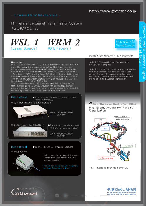
■Overview J-PARC (Japan Proton Accelerator シ
In J - PARC proton linac, 972 MHz RF reference signal is distribut- Research Complex) ス
ed to Klystron driving stations by optical fiber transmission.
In the accelerated electric field (972 MHz), the phase deviation J-PARC consists of multiple proton accelera- テ
should be ± 1 ° or less and the amplitude fluctuation should be ± tors and experimental facilities for a wide ム
1% or less. In 300 m of the linac, 60 Klystron driving stations are range of research purpose including proton
installed, so the RF reference signal requires super high stability. particle and nuclear physics, materials and
The phase deviation from station to station should be ± 0.3 ° or life science, and nuclear technology.
less (about ± 0.9 ps) at 972 MHz).
The optical components (E/O Module and O/E Module) for the
transmission devices, which Graviton has developed, provide
excellent temperature characteristics and ultra-low jitter, in addition
to clearing such a strict phase deviation requirement.
【Key Feature】 ●A Butterfly DFB Laser Diode with built-in
Peltier is mounted
WSL-1 Transmitter (1 output channel )
High Energy Accelerator Research
Organization
W430mm、D260、H44
(EIA-1U)
WSL-16 Transmitter( 出力16ch) ●16 output channel version of
WSL-1( by branch coupler )
W430mm、D360、H88
(EIA-2U)
【Key Feature】 ●WRM-2(3Gbps O/E Receiver Module)
WRM-2 Receiver
O/E conversion by digitalizing with
a transimedance amplifier and a
limiting amplifier
15
Peltier can be optionally mounted,
42mm 35 contact Graviton for details. This image is provided by KEK.
~ 26th anniversary ~ KEK-JAPAN
High Energy Accelerator
Research_Organization
Ultra-low Jitter RF Reference Signal
OOppttiiccaall lliinnkk System
Page2
WSL-1(Laser Source) / WRM-2(O/E Receiver)
■WSL-1 (Wavelength Stabilized Laser Source) ■Measurements of jitter when modulated with 960MHz
WSL-1 is a Laser source with wave-
length stabilization and modulation
function.
A DFB Laser diode with Peltier is
mounted: Direct modulation by Laser
drive current modulation is employed:
The internal circuit of the device
shapes waveform into square wave: Rising of the jitter from the non-inverting output terminal when inputting 960MHz modulation light RMS jitter: 860fs
Ultra-low jitter is provided. (including the measuring system jitter of 746fs)
■WRM-2 (O/E Receiver Module)
WRM-2 is the O/E Receiver module,
which mounts a transimpedance
amplifier and a limiting amplifier to
digitalize.
■Using a combination of WRM-2 and
WSL-1 provides ultra-low jitter of 1ps Falling of the jitter from the non-inverting output terminal when inputting 960MHz modulation light RMS jitter: 877fs
or less (See the example). (including the measuring system jitter of 741fs)
■ WSL-1 Specification Output connector of modulation
Item Description Remark SMA receptacle on the front panelmonitor signal
Model name WSL-1
Wavelength stabilized Laser source with Double Peltier system by controlling the feed-
Function
modulation function back from thermistor and Peltier built in the LDTemperature controlling of Laser
Butterfly package DFB Laser module with module and the temperature of the entire LD
Light emitting element
Peltier module
Wavelength 1550nm Setting temperature to Laser 30 ℃
Emission spectrum bandwidth 10MHz Controllable ambience temperature 20 ℃ to 40 ℃
Wavelength stability ±0.1nm or less Supply voltage and current AV100V, Max 500mA
Number of emitting device 1 430mm(W)x260mm(D)x44mm(H) Excluding protruding
Dimensions
Number of optical output channel 1 channel for EIA -1U parts, such as
Optical output level 0dBm
Compatible optical fiber Single-mode quartz optical fiber
■ WSL-2 Specification
Optical output connector FC receptacle on the front panel
Shaping waveform to Item Description Remark
Direct modulation by Laser drive current square wave by the Model name WRM-2
Light intensity modulation
modulation internal circuit of the Function 3Gbps O/E Receiver module
device Light-receiving element InGaAs PIN photodiode
Modulation rise time 200ps or less (10%-90%) Rated wavelength of receiving light 1550nm
Frequency modulation bandwidth 100kHz to 2GHz Wavelength range of receiving light 1000nm to 1650nm
800mVp-p(Recommended) Level of receiving light +1dBm to -20dBm -3dBm as standard
Modulation input level
(100mVp-p to 1Vp-p) Number of light-receiving element 1
Modulation input impedance 50Ω 0V(Terminator) , AC coupling Compatible optical fiber Single-mode quartz optical fiber
Modulation input connector SMA receptacle on the front panel Optical input connector Pigtail connector with FC plug, 1m length
Light intensity increases at a falling of the Digitalizing by a transimpedance amplifier and a
Polarity of modulation signal voltage of the modulation input signal and it O/E conversion
limiting amplifier
decreases at a rising of the voltage.
Extinction ratio of optical 7dB or greater (modulated by Pseudo Random Convertible frequency bandwidth 100kHz to 2GHz Dduty cycle : 50%
modulation Binary Sequence (PRBS) with 2.5Gbps) Signal Output level 400mVp-p 5Ωtermination
Controlling the drive current of the LD by Rise time of output signal 200ps or less (10% to 90%)
Laser output stabilization
feeding back the current monitored from the Conversion input impedance 50Ω 0V(Terminator) , AC coupling
The output terminal to send the monitor signal Number of channel to output Two outputs are in
If not used, use 50 Ω 2 channels
to external device, after shaping the waveform converted signal opposite phase
Modulated signal monitoring terminator to
of the input signal from the modulation input Output connector of conversion
terminate. SMB type receptacle
terminal. signal
Polarity of modulation signal Opposite phase to modulation input signal Supply voltage +5V
Output impedance of modulation Supply current 150mA or less
50Ω , AC coupling
monitor signal Excluding protruding
parts, such as
Dimensions of OE module 42mm(W)x35mm(D)x15mm(H)
Output level of modulation
400mVp-p or greater screws and
monitor signal connectors, etc.
Contact us Tel. +81 (42) 966-0816 Fax. +81 (42) 966-0817
Email: info@graviton.co.jp 15-5 Kawara-machi, Iruma-shi, Saitama, 350-0008, Japan
http : //www.graviton.co.jp GRAVITON is the registered trademark of Graviton Inc. No. WSL_E171030-01