


HASCO丸型ラッチロックユニットは 射出成形金型およびダイカスト金型で2つのパーティング面がある金型向けに開発されました。
様々な組み込みオプションあり
マルチポイントのロック機構により
スムーズに作動
熱膨張による位置ずれを補正
ハイサイクル成形に最適
プレートの突き出し、引っ張りが可能
ギャップフリー構造により摩耗を防止
部品同士の衝突を防止
金型内部に設置
輸送、製造、保管時の安全を確保
コンパクト設計
このカタログについて
| ドキュメント名 | HASCO 丸型ラッチロックユニット |
|---|---|
| ドキュメント種別 | 製品カタログ |
| ファイルサイズ | 1.1Mb |
| 登録カテゴリ | |
| 取り扱い企業 | 日本金型産業株式会社 (この企業の取り扱いカタログ一覧) |
この企業の関連カタログ


このカタログの内容
Page1
Neouw ość
New
NНoоuвvиeнaкuа
Z 1 176800 / ./ .. .. .
Z 1 176812/. / .. .. .
丸型ラッチロックユニット
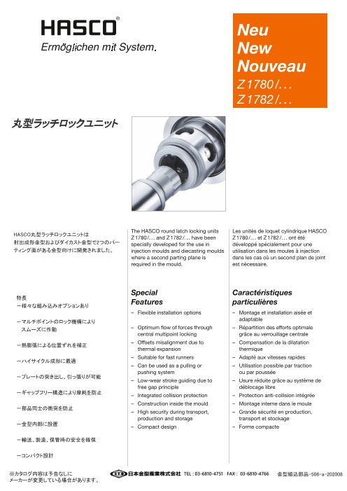
The HASCO round latch locking units Les unités de loquet cylindrique HASCO
HASCO丸型ラッチロックユニットは Z 1780 /. . . and Z 1782 /. . . have been Z 1780 /. . . et Z 1782 /. . . ont été
射出成形金型およびダイカスト金型で2つのパー specially developed for the use in développé spécialement pour une
ティング面がある金型向けに開発されました。 injection moulds and diecasting moulds utilisation dans les moules à injection
where a second parting plane is dans les cas où un second plan de joint
required in the mould. est nécessaire.
Special Caractéristiques
特長 Features particulières
-様々な組み込みオプションあり
– Flexible installation options – Montage et installation aisée et
-マルチポイントのロック機構により adaptable
スムーズに作動 – Optimum flow of forces through – Répartition des efforts optimale
central multipoint locking grâce au verrouillage centrale
– Offsets misalignment due to – Compensation de la dilatation
-熱膨張による位置ずれを補正 thermal expansion thermique
– Suitable for fast runners – Adapté aux vitesses rapides
-ハイサイクル成形に最適
– Can be used as a pulling or – Utilisation possible par traction
pushing system ou par poussée
-プレートの突き出し、引っ張りが可能 – Low-wear stroke guiding due to – Usure réduite grâce au système de
free gap principle déblocage libre
-ギャップフリー構造により摩耗を防止 – Integrated collision protection – Protection anti-collision intégrée
– Construction inside the mould – Montage interne dans le moule
-部品同士の衝突を防止 – High security during transport, – Grande sécurité en production,
production and storage transport et stockage
-金型内部に設置 – Compact design – Forme compacte
-輸送、製造、保管時の安全を確保
-コンパクト設計
※カタログ内容は予告なしに 金型組込部品-506-a-202008
メーカーが変更している場合があります。
Page2
Z 1780 /. . .
使用例 Performance Description du fonctionnement
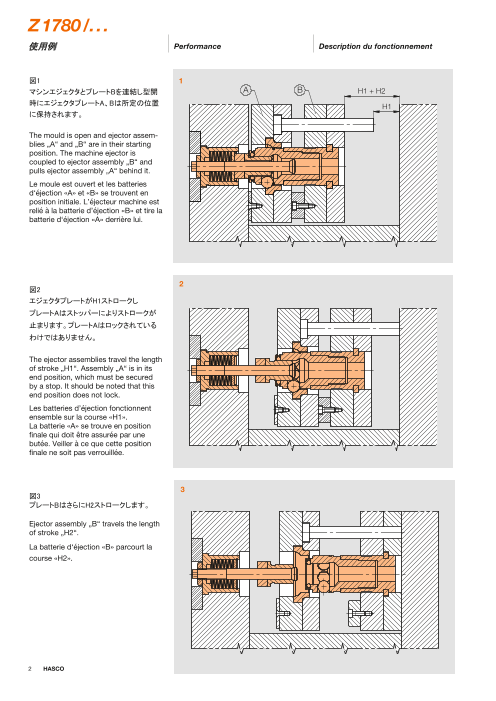
図1 1
マシンエジェクタとプレートBを連結し型開 A B H1 + H2
時にエジェクタプレートA、Bは所定の位置 H1
に保持されます。
The mould is open and ejector assem-
blies „A“ and „B“ are in their starting
position. The machine ejector is
coupled to ejector assembly „B“ and
pulls ejector assembly „A“ behind it.
Le moule est ouvert et les batteries
d‘éjection «A» et «B» se trouvent en
position initiale. L’éjecteur machine est
relié à la batterie d’éjection «B» et tire la
batterie d‘éjection «A» derrière lui.
2
図2
エジェクタプレートがH1ストロークし
プレートAはストッパーによりストロークが
止まります。プレートAはロックされている
わけではありません。
The ejector assemblies travel the length
of stroke „H1“. Assembly „A“ is in its
end position, which must be secured
by a stop. It should be noted that this
end position does not lock.
Les batteries d’éjection fonctionnent
ensemble sur la course «H1».
La batterie «A» se trouve en position
finale qui doit être assurée par une
butée. Veiller à ce que cette position
finale ne soit pas verrouillée.
3
図3
プレートBはさらにH2ストロークします。
Ejector assembly „B“ travels the length
of stroke „H2“.
La batterie d‘éjection «B» parcourt la
course «H2».
2 HASCO
Page3
Z 1780 /. . . 選定方法 Selection of the Z 1780 /. . . Sélection Z 1780 /. . .
4 1.3
L1
1,5
max. l1 l2
A
H1 - min. H1
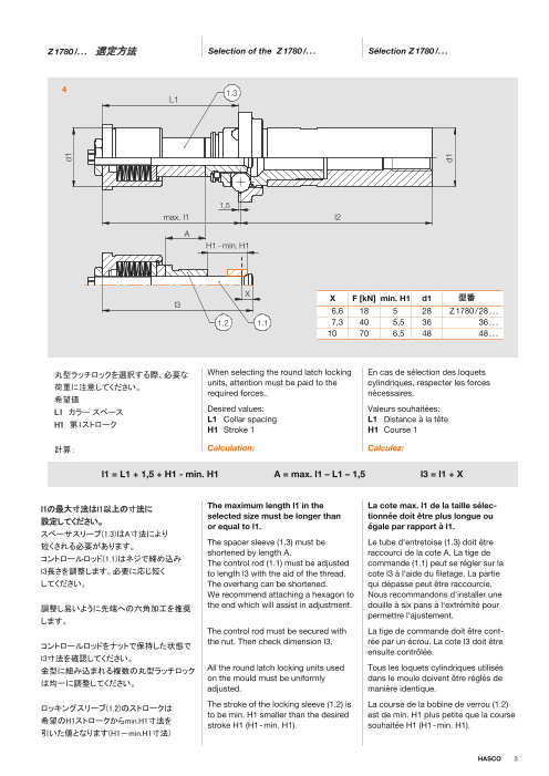
X X F [kN] min. H1 d1 型番
l3
6,6 18 5 28 Z 1780 / 28 . . .
1.2 1.1 7,3 40 5,5 36 36 . . .
10 70 6,5 48 48 . . .
丸型ラッチロックを選択する際、必要な When selecting the round latch locking En cas de sélection des loquets
units, attention must be paid to the cylindriques, respecter les forces
荷重に注意してください。 required forces.. nécessaires.
希望値
L1 カラー スペース Desired values: Valeurs souhaitées:
L1 Collar spacing L1 Distance à la tête
H1 第1ストローク H1 Stroke 1 H1 Course 1
計算: Calculation: Calculez:
l1 = L1 + 1,5 + H1 - min. H1 A = max. l1 – L1 – 1,5 l3 = l1 + X
l1の最大寸法はl1以上の寸法に The maximum length l1 in the La cote max. l1 de la taille sélec-
selected size must be longer than tionnée doit être plus longue ou
設定してください。 or equal to l1. égale par rapport à l1.
スペーサスリーブ(1.3)はA寸法により
The spacer sleeve (1.3) must be Le tube d‘entretoise (1.3) doit être
短くされる必要があります。
shortened by length A. raccourci de la cote A. La tige de
コントロールロッド(1.1)はネジで締め込み The control rod (1.1) must be adjusted commande (1.1) peut se régler sur la
l3長さを調整します。必要に応じ短く to length l3 with the aid of the thread. cote l3 à l‘aide du filetage. La partie
してください。 The overhang can be shortened. qui dépasse peut être raccourcie.
We recommend attaching a hexagon to Nous recommandons d‘installer une
調整し易いように先端への六角加工を推奨 the end which will assist in adjustment. douille à six pans à l‘extrémité pour
permettre l‘ajustement.
します。
The control rod must be secured with La tige de commande doit être cont-
the nut. Then check dimension l3. rée par un écrou. La cote l3 doit être
コントロールロッドをナットで保持した状態で ensuite contrôlée.
l3寸法を確認してください。
金型に組み込まれる複数の丸型ラッチロック All the round latch locking units used Tous les loquets cylindriques utilisés
on the mould must be uniformly dans le moule doivent être réglés de
は均一に調整してください。 adjusted. manière identique.
ロッキングスリーブ(1.2)のストロークは The stroke of the locking sleeve (1.2) is La course de la bobine de verrou (1.2)
to be min. H1 smaller than the desired est de min. H1 plus petite que la course
希望のH1ストロークからmin.H1寸法を stroke H1 (H1 - min. H1). souhaitée H1 (H1 - min. H1).
引いた値となります(H1-min.H1寸法)
HASCO 3
d1
d1
Page4
Z 1780 /. . .
組込み長さ l2 の計算 Calculation of installation length l2 Calcule de la longueur de montage l2
5
2.2
s4
1,5 a2 2.8
s4 a2 min. l2 d7 d6 d1 型番 l2
4 9 55 32 22 28 Z 1780 / 28 . . . L2
5 11 68 42 29 36 36 . . .
6 13 92 56 40 48 48 . . .
ロッキングピラー(2.2)のl2長さはご希望の Length l2 of the locking pillar (2.2) La cote l2 de la colonne de verrou (2.2)
組み込み寸法にあわせて短く出来ます。 can be shortened to the required peut être raccourcie à la longueur de
installation length. montage nécessaire.
但し、min.l2寸法より短くしないでください。 It must not be shorter than the minimum La longueur minimale min. l2 ne doit pas
ハーフリング(2.8)を固定溝に設置します。 length min. l2. être dépassée vers le bas.
The half rings supplied (2.8) can be used Les demi-bagues (2.8) fournies peuvent
L2組み込み寸法の計算式: for fastening by inserting them in a être utilisées pour la fixation dans une
fastening groove. rainure de fixation.
L2 = l2 + 1,5 Installation length L2 is calculated from: La longueur de montage L2 se calcule
comme suit:
L2 = l2 + 1,5 L2 = l2 + 1,5
Mounting dimensions Z 1780 /. . . Cotes de montage Z 1780 /. . .
Z 1780 /. . . 組込み寸法
6
H1 + H2
H1
f1x45°
6
l3 k2 s4
f1 k2 s4 l3 min. d12 d11 d10 d9 d8 d3 d1 型番
1,2 6 4 28 23 33,1 32,4 43 33 36 28 Z 1780 / 28 . . .
1,7 8 5 36 43 42,4 55 40 46 36 36 . . .
2,2 10 6 45 29 57,2 56,4 75 53 63 48 48 . . .
4 HASCO
d8
d12
d1
d1H 7
d11
d9
d3 H7
d1 H7
d10
d1
d6
d7
Page5
Z 1782 /. . .
使用例 Performance Description du fonctionnement
図7 7
マシンエジェクタとプレートAを連結します。 A B
突き出し時にプレートAがプレートBを押し H2 H1
ます。プレートBには戻り用にストッパを
設けてください。必要に応じてプレートBの
所定の位置にサポートを設置してください。
The mould is open and ejector assem-
blies „A“ and „B“ are in their starting
positions. The machine ejector is
coupled to ejector assembly „A“ and
pushes ejector assembly „B“ in front of
it. For the return stroke, a stop must be
fitted in ejector assembly „B“,
which ensures the maximum distance
between the ejector assemblies.
If necessary, a support must be
provided for the basic position of
ejector assembly „B“.
Le moule est ouvert et les batteries
d’éjection «A» et «B» se trouvent en
position initiale. L’éjecteur machine 8
est relié à la batterie d’éjection «A» et
pousse la batterie d’éjection «B» devant
lui. Une butée doit être installée dans la
batterie d’éjection «B» pour la course
de retour afin d’assurer la distance
maximale des batteries d’éjection.
La position de base de la batterie
d’éjection «B» doit être sécurisé le cas
échéant.
図8
エジェクタプレートがH1ストロークし
プレートBのストロークが止まります。
プレートBはロックされているわけでは
ありません。
The ejector assemblies travel the length
of stroke „H1“. Assembly „B“ is in its
end position. It should be noted that
this end position does not lock.
9
Les batteries d’éjection fonctionnent
ensemble sur la course «H1». La batte-
rie d’éjection «B» se trouve en position
finale. Veiller à ce que cette position
finale ne soit pas verrouillée.
図9
プレートAがさらにH2ストロークします。
Ejector assembly „A“ travels the length
of stroke „H2“.
La batterie d’éjection «A» parcourt la
course «H2».
HASCO 5
Page6
Z 1782 /. . .
Z 1782/. . . 選定方法 Selection of a Z 1782 /. . . Sélection Z 1782/. . .
10 1.3
L1
1,5
max.l1 l2
A
H1 - min. H1
X F [kN] min. H1 d1 型番
X 6,6 18 5 28 Z 1782 / 28 . . .
l3 7,3 40 5,5 36 36 . . .
10 70 6,5 48 48 . . .
1.2 1.1
丸型ラッチロックを選択する際、必要 When selecting the round latch locking En cas de sélection des loquets
な荷重に注意してください。 units, attention must be paid to the cylindriques, respecter les forces
required forces. nécessaires.
希望値 Desired values: Valeurs souhaitées:
L1 カラー スペース L1 Collar spacing L1 Distance à la tête
H1 第1ストローク H1 Stroke 1 H1 Course 1
Calculation: Calculez:
計算:
l1 = L1 – 1,5 + H1 - min. H1 A = max. l1 – L1 + 1,5 l3 = l1 + X
l1の最大寸法はl1以上の寸法に The maximum length l1 in the La cote max. l1 de la taille sélec-
設定してください。 selected size must be longer than tionnée doit être plus longue ou
or equal to l1. égale par rapport à l1.
スペーサスリーブ(1.3)はA寸法により The spacer sleeve (1.3) must be Le tube d’entretoise (1.3) doit être
短くされる必要があります。 shortened by length A. raccourci de la cote A. La tige de
コントロールロッド(1.1)はネジで締め込み The control rod (1.1) must be adjusted commande (1.1) peut se régler sur
l3長さを調整します。必要に応じ短くしてく to length l3 with the aid of the thread. la cote l3 à l’aide du filetage. La partie
ださい。 The overhang can be shortened. We qui dépasse peut être raccourcie.
recommend attaching a hexagon to the Nous recommandons d’installer une
調整し易いように先端への六角加工を推
end which will assist in adjustment. douille à six pans à l’extrémité pour
奨します。 permettre l’ajustement.
コントロールロッドをナットで保持した状態 The control rod must be secured with La tige de commande doit être
でl3寸法を確認してください。 the nut. Then check dimension l3. contrée par un écrou. La cote l3 doit
être ensuite contrôlée.
金型に組み込まれる複数の丸型ラッチロッ All the round latch locking units used on Tous les loquets cylindriques utilisés
クは均一に調整してください。 the mould must be uniformly adjusted. dans le moule doivent être réglés de
manière identique.
ロッキングスリーブ(1.2)のストロークは The stroke of the locking sleeve (1.2) is La course de la bobine de commande
希望のH1ストロークからmin.H1寸法を to be min. H1 smaller than the desired (1.2) est de min. H1 plus petite que la
引いた値となります(H1-min.H1寸法) stroke H1 (H1 - min. H1). course souhaitée H1 (H1 - min. H1).
6 HASCO
d1
d1
Page7
組込み長さ l2の計算 Calculation of installation length l2 Calcule de la longueur de montage l2
11
2.2
s4
1,5 a2
s4 a2 min. l2 d7 d6 d1 型番 2.8
L2
4 9 55 32 22 28 Z 1782 / 28 . . .
5 11 68 42 29 36 36 . . . l2
6 13 92 56 40 48 48 . . .
ロッキングピラー(2.2)のl2長さはご希望の Length l2 of the locking pillar (2.2) can La cote l2 de la colonne de verrou (2.2)
組み込み寸法にあわせて短く出来ます。 be shortened to the required installation peut être raccourcie à la longueur de
length. montage nécessaire.
但し、min.l2寸法より短くしないでください。
ハーフリング(2.8)を固定溝に設置します。 It must not be shorter than the minimum La longueur minimale min. l2 ne doit pas
length min. l2. être dépassée vers le bas.
L2組み込み寸法の計算式: The half rings supplied (2.8) can be used Les demi-bagues (2.8) fournies peuvent
for fastening by inserting them in a être utilisées pour la fixation dans une
L2 = l2 – 1,5 fastening groove. rainure de fixation.
Installation length L2 is calculated from: La longueur de montage L2 se calcule
comme suit:
L2 = l2 – 1,5 L2 = l2 – 1,5
Mounting dimensions Z 1782 /. . . Cotes de montage Z 1782 /. . .
Z 1782 /. . . 組込み寸法
12 l5 H2 H1
k2
6 f1x4 5° s4
f1 k2 s4 l5 (l4* + 2) d13 min. d12 d11 d10 d9 d8 d3 d1 型番
1,2 6 4 12 + 2 38 23 33,1 32,4 43 33 36 28 Z 1780 / 28 . . .
1,7 8 5 15 + 2 48 43 42,4 55 40 46 36 36 . . .
2,2 10 6 19 + 2 65 29 57,2 56,4 75 53 63 48 48 . . .
HASCO 7
d8
d12
d1
d1 H7
d13
d3 H 7
d11
d9
d1 H7
d10
d1
d6
d7
Page8
Z 1780 /. . .
Rundklinkeneinheit, Zugsystem
Round latch unit, pulling system
Loquet cylindrique, système de traction
max. °C: 180
l4
l3 k2
r1
6
s3 24
l5 1,5
max.l1 l2
max.a1
d7
max. min. min. min. max. max.
H1 H1 r1 k2 s4 s3 l5 l4 l3 l2 l1 d7 d6 d4 d3 d2 d1 l1 a1 l2 型番
21 5 1 6 4 4,5 9 12 28 55 48 32 22 42 36 32 28 64 16 96 Z 1780 / 28 x 64 x 16 x 96
37 64 80 32 80 x 32
53 80 96 48 96 x 48
29,5 5,5 1,5 8 5 15 36 68 60 42 29 54 46 39 36 84 24 116 Z 1780 / 36 x 84 x 24 x 116
53,5 84 108 48 108 x 48
77,5 108 132 72 132 x 72
101,5 132 156 96 156 x 96
36,5 6 2 10 6 5,5 11 19 45 92 76,5 56 40 74 63 52 48 106,5 30 136 Z 1780 / 48 x 106,5 x 30 x 136
66,5 106,5 136,5 60 136,5 x 60
96,5 136,5 166,5 90 166,5 x 90
126,5 166,5 196,5 120 196,5 x 120
8 HASCO
d2
d1
d3
d4
s4
d6
M16
d1
Page9
Z 1782 /. . .
Rundklinkeneinheit, Schubsystem
Round latch unit, pushing system
Loquet cylindrique, système de poussée
max. °C: 180
l4
l3 k2
6
s3 24
r1
l5 1,5
max.l1 l2
max.a1
d7
max. min.
H1 H1 r1 k2 s4 s3 l5 l4 l3 min. min. max. max. max.
l2 l1 d7 d6 d4 d3 d2 d1 l1 a1 H2 l2 型番
21 5 1 6 4 4,5 9 33 28 55 48 32 22 42 36 32 28 64 16 30 96 Z 1782 / 28 x 64 x 16 x 30 x 96
43 40 40
37 33 64 80 32 30 Z 1782 / 28 x 80 x 32 x 30 x 96
43 40 40
53 50 50
63 60 60
53 33 80 96 48 30 Z 1782 / 28 x 96 x 48 x 30 x 96
43 40 40
53 50 50
63 60 60
29,5 5,5 1,5 8 5 33 36 68 60 42 29 54 46 39 36 84 24 30 116 Z 1782 / 36 x 84 x 24 x 30 x 116
43 40 40
53 50 50
63 60 60
53,5 33 84 108 48 30 Z 1782 / 36 x 108 x 48 x 30 x 116
43 40 40
53 50 50
63 60 60
HASCO 9
d2
d1
d3
d4
s4
d6
M16
d1
Page10
Z 1782 /. . .
Rundklinkeneinheit, Schubsystem
Round latch unit, pushing system
Loquet cylindrique, système de poussée
max. °C: 180
l4
l3 k2
6
s3 24
r1
l5 1,5
max.l1 l2
max.a1
d7
max. min. r1 k2 s4 s3 l5 l4 l3 min. min. d7 d6 d4 d3 d2 d1 max. max. max.
H1 H1 l1 l1 l1 a1 H2 l2 型番
77,5 5,5 1,5 8 5 4,5 9 33 36 68 108 42 29 54 46 39 36 132 72 30 116 Z 1782 / 36 x 132 x 72 x 30 x 116
43 40 40
53 50 50
63 60 60
101,5 33 132 156 96 30 Z 1782 / 36 x 156 x 96 x 30 x 116
43 40 40
53 50 50
63 60 60
36,5 6,5 2 10 6 5,5 11 43 45 92 76,5 56 40 74 63 52 48 106,5 30 40 136 Z 1782 / 48 x 106,5 x 30 x 40 x 136
53 50 50
63 60 60
66,5 43 106,5 136,5 60 40 Z 1782 / 48 x 136,5 x 60 x 40 x 136
53 50 50
63 60 60
96,5 43 136,5 166,5 90 40 Z 1782 / 48 x 166,5 x 90 x 40 x 136
53 50 50
63 60 60
126,5 43 166,5 196,5 120 40 Z 1782 / 48 x 196,5 x 120 x 40 x 136
53 50 50
63 60 60
10 HASCO
d2
d1
d3
d4
s4
d6
M16
d1
Page11
Z 17800 /. . .
Verriegelungseinheit, Zugsystem
Locking unit, pulling system
Unité de verrou, système de traction
max. °C: 180
l4
k2
24
1,5
l2
d7
r1 k2 s4 l4 d7 d6 d4 d3 d1 l2 型番
1 6 4 12 32 22 42 36 28 96 Z 17800 / 28 x 96
1,5 8 5 15 42 29 54 46 36 116 36 x 116
2 10 6 19 56 40 74 63 48 136 48 x 136
HASCO 11
d3
d4
s4
d6
M16
d1
r1
Page12
Z 17810 /. . .
Steuereinheit
Control unit
Unité de commande
max. °C: 180
l3
6
s3
l5
max. l1
max. a1
max. H1 min. H1 s3 l5 l3 min.l1 d2 d1 max. l1 max. a1 型番
21 5 4,5 9 28 48 32 28 64 16 Z 17810 / 28 x 64 x 16
37 64 80 32 80 x 32
53 80 96 48 96 x 48
29,5 5,5 36 60 39 36 84 24 Z 17810 / 36 x 84 x 24
53,5 84 108 48 108 x 48
77,5 108 132 72 132 x 72
101,5 132 156 96 156 x 96
36,5 6,5 5,5 11 45 76,5 52 48 106,5 30 Z 17810 / 48 x 106,5 x 30
66,5 106,5 136,5 60 136,5 x 60
96,5 136,5 166,5 90 166,5 x 90
126,5 166,5 196,5 120 196,5 x 120
12 HASCO
d2
d1
Page13
Z 17820 /. . .
Verriegelungseinheit, Schubsystem
Locking unit, pushing system
Unité de verrou, système de poussée
max. °C: 180
l4
k2
l6
r1 1,5
l2
d7
r1 k2 s4 l4 d7 d6 d4 d3 d1 max. H2 l2 型番
1 6 4 33 32 22 42 36 28 30 96 Z 17820 / 28 x 30 x 96
43 40 40
53 50 50
63 60 60
1,5 8 5 33 42 29 54 46 36 30 116 Z 17820 / 36 x 30 x 116
43 40 40
53 50 50
63 60 60
2 10 6 43 56 40 74 63 48 40 136 Z 17820 / 48 x 40 x 136
53 50 50
63 60 60
HASCO 13
d3
d4
s4
d6
M16
d1
Page14
Z 1780 /. . .
パーツリスト Parts list Liste de pièces
1 Z 17810 /. . . 2 Z 17800 /. . .
1.5 1.4 1.3 1.2 2.3 2.2
1.8 1.6 1.7 1.1 2.7 2.6 2.4 2.5 2.1
2.8
Stück
Pos. 名称 Designation Désignation Quantity
Pièce
1 コントロールユニット Control unit Unité de commande 1
1.1 コントロールロッド Control rod Tige de commande 1
1.2 ロッキングスリーブ Locking sleeve Bobine de verrou 1
1.3 スリーブ Distance sleeve Tube d’entretoise 1
1.4 コントロールロッドホルダ Control rod holder Support de tige de commande 1
1.5 ナット Nut Écrou pour rainures en T 1
1.6 カバー Cover Couvercle 1
1.7 ロッキングリング Locking ring Circlip 1
1.8 スプリング Disc spring Rondelle élastique 12 (14)
2 ロッキングユニット Locking unit, pulling system Unité de verrou, système de traction 1
2.1 ロッキングヘッド Locking head Tête de verrou 1
2.2 ロッキングピラー Locking pillar Colonne de verrou 1
2.3 スリーブ Pulling sleeve Douille de traction 1
2.4 ボール Ball Bille 5
2.5 ロッキングリング Locking ring Circlip 1
2.6 ボール Ball Bille 2
2.7 ロッキングリング Locking ring Circlip 1
2.8 ハーフリング Mounting ring Bague de fixation 2
14 HASCO
Page15
Z 1782 /. . .
パーツリスト Parts list Liste de pièces
1 Z 17810 /. . . 2 Z 17820 /. . .
1.5 1.4 1.3 1.2 2.3 2.2
1.8 1.6 1.7 1.1 2.7 2.6 2.4 2.5 2.1
2.8
Stück
Pos. 名称 Designation Désignation Quantity
Pièce
1 コントロールユニット Control unit Unité de commande 1
1.1 コントロールロッド Control rod Tige de commande 1
1.2 ロッキングスリーブ Locking sleeve Bobine de verrou 1
1.3 スリーブ Distance sleeve Tube d’entretoise 1
1.4 コントロールロッドホルダ Control rod holder Support de tige de commande 1
1.5 ナット Nut Écrou pour rainures en T 1
1.6 カバー Cover Couvercle 1
1.7 ロッキングリング Locking ring Circlip 1
1.8 スプリング Disc spring Rondelle élastique 12 (14)
2 ロッキングユニット Locking unit, pushing system Unité de verrou, système de poussée 1
2.1 ロッキングヘッド Locking head Tête de verrou 1
2.2 ロッキングピラー Locking pillar Colonne de verrou 1
2.3 スリーブ Pushing sleeve Douille de traction 1
2.4 ボール Ball Bille 5
2.5 ロッキングリング Locking ring Circlip 1
2.6 ボール Ball Bille 2
2.7 ロッキングリング Locking ring Circlip 1
2.8 ハーフリング Mounting ring Bague de fixation 2
HASCO 15
Page16
© by HASCO Hasenclever GmbH + Co KG · Postfach 1720 · D-58467 Lüdenscheid · Tel. +49 2351 957-0 · Fax +49 2351 957-237 · info@hasco.com · www.hasco.com 10 19 2 1,5 26
Technische Änderungen vorbehalten. Bitte überprüfen Sie stets sämtliche Angaben anhand unserer veröffentlichten Produktinformationen im Internet.
Subject to technical modifications. Please always check all the data against the product information we publish in the internet.
Sous réserve de modifications techniques. Veuillez toujours vérifier toutes les données au moyen de nos informations produits publiées sur Internet.