


『最先端のロボット制御の研究』『研究の効率・生産性の向上』
【FRANKA RESEARCH 3 特徴】
◆ROS(Robot Operating System)対応
◆全軸にトルクセンサー搭載
◆簡単ダイレクトティーチング
◆高い安全性
研究や製品開発に於ける定常作業・単調作業を協働ロボットに任せることで、人間は付加価値の高い研究に注力する動きがあります。また、コロナ禍により研究室や実験室で作業ができない状況でもロボットを利用することで必要作業を継続することが可能です。しかし、研究現場の多くは、十分なスペースを確保することが難しいという難点があります。
FRANKA RESEARCH 3は協働ロボットによる「狭所作業」や「人や周辺物との安全な接触」のような課題に対応できる製品になります。
[キーワード]
#協働ロボット #7軸 #コボット #ROS #産業ロボット #少量多品種 #繰り返し #AI #自動化 #省人化 #工場 #生産性向上 #IoT #スマートファクトリー #Franka #Emika #FrankaEmika #FRANKAEMIKA #海外
このカタログについて
| ドキュメント名 | 【7軸 協働ロボット】FRANKA RESEARCH 3 <ROS対応> |
|---|---|
| ドキュメント種別 | 製品カタログ |
| ファイルサイズ | 1.3Mb |
| 取り扱い企業 | リョーサン菱洋株式会社 (この企業の取り扱いカタログ一覧) |
この企業の関連カタログ


このカタログの内容
Page1
FR3表紙、スライド番号 1
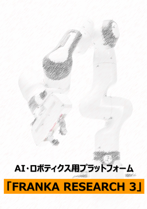
AI・ロボティクス用プラットフォーム
「FRANKA RESEARCH 3」
Page2
FRANKA_Flyer_230314、スライド番号 1
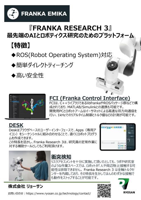
『FRANKA RESEARCH 3』
最先端のAIとロボティクス研究のためのプラットフォーム
【特徴】
◆ROS(Robot Operating System)対応
◆簡単ダイレクトティーチング
◆高い安全性
FCI (Franka Control Interface)
FCIは、C++ライブラリであるlibfrankaやROSパッケージ群などで構
成されており、MATLAB/Simulinkとの連携も可能です。
開発用PCとロボットアームはイーサネットによる高速な双方向通信を
行い、1kHzでのリアルタイム制御とトルク値などの計測が可能です。
DESK
Deskはブラウザベースのユーザーインターフェースで、Apps(専用ア
イコン)をシーケンシャルに組み合わせることで、直ぐにロボットプログラ
ムを作成できます。
この特長を活かし、Franka Research 3は、研究員の定常作業に
対する補助ツールとしてもご利用頂けます。
衝突検知
リスクアセスメントを十分に実施して頂いたとしても、ラボや研究室
のような作業スペースでは、ロボットが「人や周辺物」と接触する可
能性は排除できません。 Franka Research 3 は全軸トルクセ
ンサーを内蔵しており、その特長を生かしてほんのわずかな接触で
も動作をストップすることが可能です。
株式会社 リョーサン
お問い合わせ:https://www.ryosan.co.jp/technology/contact/
Page3
スライド番号 2
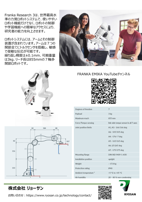
Franka Research 3は、世界最高水
準の力覚ロボットシステムで、使いやすい
ロボット機能だけでなく、ロボットの制御
や学習機能への簡単なアクセスにより、
研究者の能力を向上させます。
ロボットシステムには、アームとその制御
装置が含まれています。アームは7つの
関節全てにトルクセンサを搭載し、敏感
で俊敏な反応が可能です。
繰り返し精度は±0.1mm、可搬重量
は3kg、リーチ長は855mmの7軸多
関節ロボットです。
FRANKA EMIKA YouTubeチャンネル
株式会社 リョーサン
お問い合わせ:https://www.ryosan.co.jp/technology/contact/
Page4
Aperza_Catalog_Download_D10100000062914
FRANKA RESEARCH 3
Datasheet
Page5
Franka Research 3
Version: June 2022
Datasheet ¹
Arm & Control
ARM
Degrees of freedom 7 Interfaces • ethernet (TCP/IP) for visual intuitive
programming with Desk
Payload 3 kg
• safety-rated input for external enabling device
Maximum reach 855 mm
• 2 configurable safety-rated inputs for
Force/Torque sensing link-side torque sensor in all 7 axes
emergency stop devices, safeguards or other
Joint position limits A1, A3: -166/166 deg protective devices (OSSD devices via external
A2: -105/105 deg OSSD converter connectable)
•
A4: -176/-7 deg hardware prepared for: 2x DI & 2x DO
(24V, isolated, EN 61131-2 type 3
A5: -165/165 deg characteristics, 100 Hz sampling rate)
A6: 25/265 deg • Control connector
A7: -175/175 deg • connector for end effector
Mounting flange DIN ISO 9409-1-A50
Installation position upright User Interfaces at the • integrated safety-rated guiding enabling switch
Arm's Pilot Grip
Weight ~ 17.8 kg • guiding button
Protection rating IP40 • guiding mode selector
Air humidity 20 − 80 % non-condensing
User Interfaces at the • status light
Arm's Pilot Disc
• Pilot mode selector
• arrow keys, teach, confirm, delete
CONTROL PERFORMANCE
Controller size (19”) 355 x 483 x 89 mm (D x W x H) Motion
Supply voltage 100 − 240 VAC Joint velocity limits A1-A4: 150 °/s
Mains frequency 50− 60 Hz A5-A7: 301 °/s
Power consumption ~ 80 W Cartesian velocity limits up to 2 m/s end effector speed
Active power factor correction (PFC) yes Pose repeatability ² <+/- 0.1 mm (ISO 9283)
Weight ~ 7 kg
Protection rating IP20 Interaction
Air humidity 20 − 80 % non-condensing Guiding force ~ 2.5 N
Permitted mounting orientation horizontal Adjustable translational stiffness 10 − 3000 N/m
Interfaces • ethernet (TCP/IP) for internet Adjustable rotational stiffness 1 − 300 Nm/rad
and/or shop-floor connection
Monitored signals joint position, velocity,
• power connector torque cartesian position, force
IEC 60320C14 (V-Lock)
• Arm connector ADD-ONS
EXCLUSIVE Fully integrated end effectors • 2-finger gripper
•
Research interface 1kHz Franka Control Interface Vacuum gripper
(FCI) Fieldbuses • Modbus/TCP
• OPC UA
Copyright © Franka Emika
Page6
Franka Research 3
Version: June 2022
SAFETY
Compliance
EN ISO 10218-1:2011 Robots and robotic devices -
safety requirements for industrial robots Part 1: Robots
EN ISO 13849:2015 safety of machinery -
safety-related parts of control systems
Collaborative operation modes
Safety-rated monitored stop fully integrated in PL d Cat. 3
Hand-guiding fully integrated in PL d Cat. 3
Safety-rated speed and separation monitoring realizable in combination with external protective devices up to PL d Cat. 3
Safety parametrization & validation
Watchman user interface to set and validate safety-related parameters
User management role based access management
Safety Functions
Emergency Stop (X3.1) PL d / Cat. 3
External Enabling Device (X4) PL d / Cat. 3
Enabling Button PL d / Cat. 3
Two configurable safe inputs (X3.2 and X3.3) PL d / Cat. 3
SLP-C: Safely limited Cartesian position PL d / Cat. 3 note: FCI cannot control the robot while SLP-C is active
SLS-C: Safely limited Cartesian speed PL d / Cat. 3 note: FCI cannot control the robot while SLS-C is active
SLP-J: Safely limited joint angle PL d / Cat. 3
SLS-J: Safely limited joint speed PL d / Cat. 3
SLD: Safely limited distance PL d / Cat. 3
SEEPO: Safe End Effector Power off PL b / Cat. b
Stopping Functions
Category 0 stop PL d / Cat. 3
Category 1 stop PL d / Cat. 3
Category 2 stop PL d / Cat. 3
1. Technical data are subject to change.
2. Based on ISO 9283 (Annex A), specified values refer to a workspace of 0.4 x 0.4 x 0.4 m centered at [0.498, 0.0, 0.226] m,
with the Z-Axis of the flange oriented parallel to earth-gravity and the elbow positioned upwards.
Copyright © Franka Emika
Page7
Franka Research 3
Version: June 2022
DIMENSIONS & WORKSPACE
82 384 88
A5 A6
82 107
A4 A7 X
Y
A3
316
Z
A2
Z
333
A1
Y X
Axes names with joint lengths [mm]
855 855
1188
R 80 5
reach with flange // to base
333
R 855
max. reach of flange
ISO CUBE
362 365
280 280
Workspace | side view [mm] Workspace | top view [mm]
Copyright © Franka Emika
ISO CUBE