


ボタン形ニッケル水素二次電池ハンドブック Sales Program and Technical Handbook Rechargeable Button Cells NiMH
製品カタログ
VARTA Microbattery is a leading firm in the field of batteries and provides professional support for customers with engineered design-in applications worldwide. Quality, reliability, high performance and customer satisfaction are the main reasons for our leading position in the market. VARTA Microbattery provides solutions to major OEM companies for high-tech applications such as notebook/pda bridging function, memory backup and real-time clock in PCs/notebooks as well as power source for telecom devices, remote control devices, torches, domestic alarms, car alarms, medical equipment, consumer electronics, solar applications and many more.
このカタログについて
| ドキュメント名 | ボタン形ニッケル水素二次電池ハンドブック Sales Program and Technical Handbook Rechargeable Button Cells NiMH |
|---|---|
| ドキュメント種別 | 製品カタログ |
| ファイルサイズ | 4.1Mb |
| 登録カテゴリ | |
| 取り扱い企業 | ファルタ・マイクロバッテリー・ジャパン株式会社 (この企業の取り扱いカタログ一覧) |
この企業の関連カタログ


このカタログの内容
Page1
Rechargeable
Button Cells
NiMH
Sales Program and
Technical Handbook
www.varta-microbattery.com
6203 0216
Page2
Rechargeable Button Cells
CONTENT
1. GENERAL INFORMATION 3–8
1.1 Product families 4–6
1.2 General Design and Application Criteria 7
2. ASSORTMENT V...H(T) ROBUST (85) 9–24
2.1 Construction and Electrochemical Processes of NiMH
High Rate Button Cells 10
2.2 Features V…H(T) Robust (85) 11
2.3 NiMH High Rate Button Cell Batteries for Bridging, Hot Swap and
Memory Protection Applications 12
2.4 NiMH Button Cell Batteries for Memory Protection 13
2.5 NiMH Button Cell Batteries for Bridging Applications 14
2.6 Standard NiMH Button Cell Batteries for Alarm Equipment (Car Alarm, …) 15
2.7 Standard NiMH Button Cell Batteries for Electronic Equipment 16–18
2.8 Charging Methods for NiMH Button Cells Robust Family 19–20
2.9 Recommended Charging Circuits 21
2.10 Charge Table for NiMH Button Cells 22
2.11 Discharge Characteristics of NiMH Button Cells 23
2.12 Discharge Diagram of NiMH Button Cells Robust Family 24
3. ASSORTMENT V...HR(T) POwERFUL (85) 25–38
3.1 Construction and Electrochemical Processes of NiMH High Rate
Button Cells 26
3.2 Features V…HR(T) Powerful (85) 27
3.3 NiMH High Rate Button Cell Batteries for Innovative IT
and Automotive Applications 28
3.4 Examples of NiMH HIGH RATE Button Cell V…HR(T) Assemblies 29
3.5 Charging methods for Powerful Family 30–31
3.6 Charge Table for NiMH High Rate Button Cells V…HR(T) 32
3.7 Typical Charging Curves at Various Temperatures and Rates Robust (85) 33–34
3.8 Discharge Characteristics of NiMH High Rate Button Cells 35
3.9 Discharge Diagrams of NiMH High Rate Button Cells V…HR(T)
Powerful Family 36–37
3.10 Permissible Temperature Range 38
4. GENERAL CHARACTERISTICS 39–51
4.1 References 39
4.2 Reliability and Life Expectancy 40–41
4.3 Proper use and Handling 42–44
4.4 Transportation, Safety and Recycling Note for Batteries 45
4.5 Storage/Handling 46
4.6 Battery Assembly 47
4.7 Multicell Batteries 48
4.8 Definitions 49–50
4.9 Application Check List 51
Page3
1. GENERAL INFORMATION
VARTA Microbattery is a leading firm in the field of batteries and provides professional support for customers with
engineered design-in applications worldwide. Quality, reliability, high performance and customer satisfaction are the
main reasons for our leading position in the market. VARTA Microbattery provides solutions to major OEM companies
for high-tech applications such as notebook/pda bridging function, memory backup and real-time clock in PCs/note-
books as well as power source for telecom devices, remote control devices, torches, domestic alarms, car alarms,
medical equipment, consumer electronics, solar applications and many more.
Key Features – Benefits
n Safety: built-in pressure vent guarantees safety in case n O vercharge capability: cost effective charging system
of mistreatment with no need for special components due to patented
n Low self discharge: no handling, no charging – ready GCE electrode
to use after storage due to superior self discharge n Deep discharge capability: longer lasting shelf-life with
performance high capacity retention after deep discharge
n Cycle Life: extended product life time of more than n No leakage: direct mounting on PCB possible due to
1000 cycles (IEC) patented crimp sealing system
System highlights of NiMH Button Cells from
VARTA Microbattery:
n Excellent high-rate discharge characteristics n Good recovery characteristics after long storage period
(3 CA/5 CA). For short duration even higher currents and deep discharge
can be drained. n 0% lead, 0% mercury and 0% cadmium
n No memory effect n UL Recognition
n Long life – typical 500 full cycles n ISO 9000 certified for design and manufacture of
n Good overcharge capability rechargeable mass type cells and batteries. Conformity
n Low self-discharge to requirements of ISO 9001
n Flat discharge voltage n V ARTA Microbattery is a leader of NiMH Button Cell
n Slim design technology and received several ecological and industry
n wide temperature range awards.
- Storage: -40°C up to +65°C/+85°C
- Discharge: -20°C up to +65°C/+85°C
- Charge: 0°C up to +65°C/+85°C
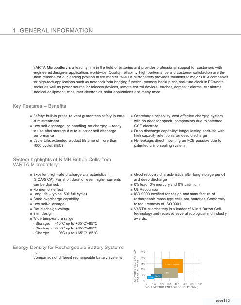
Energy Density for Rechargeable Battery Systems
FIG. 1
Comparison of different rechargeable battery systems
page 2 | 3
Page4
Rechargeable Button Cells
1.1 PRODUCT FAMILIES
Four button cell families with specific strengths and
features provide the ideal battery solution for any
application. Each family has its speciality to provide
optimum solution for dedicated application areas.
Product Overview
Type Designation Type No. Voltage Capacity Diameter Height Length Width Weight
(V) (mAh) (mm) (mm) (mm) (mm) (g)
V…H robust
V 15 H 55602 1.2 16 11.5 3.1 1.3
V 30 H 55603 1.2 28 11.5 3.85 1.3
V 40 H 55604 1.2 43 11.5 5.35 1.7
V 80 H 55608 1.2 80 15.5 6.0 4.0
V 150 H 55615 1.2 150 5.85 14.1 25.6 6.0
V 200 H 55620 1.2 210 7.4 14.1 25.6 7.0
V 250 H 55625 1.2 250 25.1 6.7 10.0
CP 300 H 55630 1.2 300 25.1 7.55 11.0
V 350 H 55635 1.2 380 25.1 8.8 13.0
V…HT robust85C
V 65 HT 55707 1.2 70 15.5 6.0 4.0
V 150 HT 55716 1.2 150 5.85 14.1 25.6 6.0
V…HR powerful
V 6 HR 55996 1.2 6.2 6.8 2.15 0.28
V 450 HR 55945 1.2 450 5.6 24.1 34.1 12.5
V 600 HR 55960 1.2 600 6.8 24.1 34.1 14.5
V…HRT powerful85C
V 18 HRT 55802 1.2 19 11.5 2.3 0.9
V 150 PT 55815 1.2 150 3.6 24.1 34.1 7.5
V 500 HT 55750 1.2 500 6.8 24.2 34.1 14.0
V 600 HRT 55860 1.2 600 6.8 24.1 34.1 14.5
TAB. 1
Page5
Capacity Range
From V 6 HR to V 600 HRT, from 6 mAh up to
600 mAh – VARTA provides a full programme of
rechargeable button cells for all performance
requirements.
Quality – Made in Germany
n Manufactured on highly automated lines
n Direct replacement for NiCd
n No memory effect
n 0% lead, 0% mercury and 0% cadmium
n UL Recognition under file BBET2.MH13654
V…H V…HT
robust robust85C
High performance button cell with superior overcharge High performance button cell with superior overcharge
stability and discharge currents ≤ 2 CA. stability and discharge currents ≤ 2 CA at high temperature.
Based on mass electrode technology, temperature range Based on mass electrode technology, temperature range
-20°C to +65°C. -20°C to +85°C.
Typical Applications: Typical Applications:
■ Memory Backup ■ Real Time Clock ■ Mobile Light ■ Industrial Electronics ■ Automotive Applications
Type Designation Type No. Voltage (V) Capacity (mAh) Type Designation Type No. Voltage (V) Capacity (mAh)
V 15 H 55602 1.2 16 V 65 HT 55707 1.2 70
V 30 H 55603 1.2 28 V 150 HT 55716 1.2 150
V 40 H 55604 1.2 43
V 80 H 55608 1.2 80
V 150 H 55615 1.2 150
V 200 H 55620 1.2 210
V 250 H 55625 1.2 250
CP 300 H 55630 1.2 300
V 350 H 55635 1.2 380
TAB. 2 TAB. 3
page 4 | 5
Page6
Rechargeable Button Cells
V…HR V…HRT
powerful powerful85C
High rate button cell with superior load capability for dis- High rate and high temperature button cell with superior load
charge currents up to 5 CA. capability for discharge currents up to 5 CA at high temperature.
Based on foam electrode technology, temperature range Based on foam electrode technology, temperature range
-20 to +65°C. -20 to +85°C.
Typical Applications: Typical Applications:
■ Consumer Electronics ■ Health Care Devices ■ Automotive Electronics ■ Server, Computer
■ Wireless Headsets, Headphones ■ Emergency Light, Solar Light
Type Designation Type No. Voltage (V) Capacity (mAh) Type Designation Type No. Voltage (V) Capacity (mAh)
V 6 HR 55996 1.2 6.2 V 18 HRT 55802 1.2 19
V 450 HR 55945 1.2 450 V 150 PT 55815 1.2 150
V 600 HR 55960 1.2 600 V 500 HT 55750 1.2 500
V 600 HRT 55860 1.2 600
TAB. 4 TAB. 5
Battery Guide
Four button cell
families with specific
strengths and
features provide the
ideal battery solution V…H robust ++ ++ ++ +++ ++ + + +
for any application. V…HT robust85C ++ +++ ++ +++ ++ + ++ ++
V…HR powerful + + + +++ + +++ + +
V…HRT powerful85C + + + +++ + ++ ++ ++
TAB. 6
self
discharge
over-
charge
deep
discharge
cycle
life
storage
behaviour
high rate
capability
charge efficiency
at high temp.
temperature
range
Page7
1.2 GENERAL DESIGN AND APPLICATION CRITERIA
The choice of the most suitable cells or battery types
is exclusively related to the type of application and the
operating conditions.
The most important criteria for selection are
as follows:
n Type of operation of the cell, i.e. cyclic operation n Temperature during use
(continuous sequence of charge/discharge) or standby n Duration and level of load (continuous pulsed)
operation, trickle charged n Operating voltage required with voltage limiting values
n Available space n Charging conditions
n Maximum weight
The relevant cell data can be found in the corresponding
sections of this catalogue. The data comprises standard
values for planning purposes. As such they describe the
performance for each cell type and always refer to single
cells.
For the assembly of batteries we will assist you with all
our long experience and expertise.
Standard battery assemblies up to 10 cells (12 V nomi-
nal voltage) are available.
Assemblies with higher numbers of cells are possible
under certain application conditions. Ask us – we will
advise you.
For further orientation and planning, please find a check
list on page 51 of this handbook.
page 6 | 7
Page8
Rechargeable Button Cells
Page9
2. ASSORTMENT V…H(T) ROBUST (85)
Page10
Rechargeable Button Cells
2.1 C ONSTRUCTION AND ELECTROCHEMICAL PROCESSES
OF NIMH BUTTON CELLS
A special sealing design maximizes the diffusion path A sealed NiMH Button Cell requires that towards the end
and guarantees optimal protection against leakage. The of the charging process, oxygen which is generated at
cup of the casing acts as the positive terminal and the the positive electrode must be consumed to avoid pres-
lid as the negative terminal. The punched positive sign sure build-up (charge reserve). Additionally a discharge
on the cell is used as a safety device which opens at reserve is necessary to prevent degradation of the nega-
predetermined internal pressure, in case of gross abuse. tive electrode at the end of discharge. In general the
Some cells are interchangeable with 1.5 V primary cells negative electrode is overdimensioned compared with
of identical dimensions. the positive, which determines the usable cell capacity
(Fig. 2).
FIG. 2
Schematic view of a
NiMH Button Cell
CUP – Nickel-plated steel, acting as positive terminal
POSITIVE ELECTRODE (NICKEL HYDROxIDE) – Mainly nickel
hydroxide, enclosed in wire mesh
wIRE MESH
SEALING RING
SEPARATOR – Non-woven material having excellent electrical
insulation characteristics retaining a suitable amount of electrolyte
for ion transport
LID – Nickel-plated steel, acting as negative terminal
NEGATIVE ELECTRODE (METAL HYDRIDE) – Metal hydride,
a hydrogen storage alloy, enclosed in wire mesh
Chemical Process of Charging/Discharging
Charging NiOOH/Ni(OH)2 +
Ni(OH)2 + Metal NiOOH + MH Positive electrode
Discharging
Charge product of the positive electrode: Nickel (III) oxyhydroxide – NiOOH Useful capacity
Charge product of the negative electrode: Metal hydride Negative electrode
Discharge product of the positive electrode: Nickel (II) hydroxide – Ni(OH)2 MH-Metal –
Discharge product of the negative electrode: Metal alloy
Electrolyte: Alkaline solution (KOH) Charge reserve Discharge reserve
FIG. 3
Schematic representation of the elec trodes,
demonstrating useful capacity, charge reserve
and discharge reserve
Page11
2.2 FEATURES V…H(T) ROBUST (85)
n Cells with typical capacities from 16 up to 380 mAh n L ong life expectancy
n N ominal cell voltage 1.2 V n Self-discharge less than 10% after 1 month
n w ide operating temperature range at +20°C
n Built-in safety device n High temperature range V…HT
n UL Recognition - High capacity
n Limited fast charge possible (within 3 h at 0.5 CA, at - Long life expectancy
+20°C, after fully discharged cells) especially at charging/trickle charging and discharging
n Suitable for overcharging at room temperature at higher ambient temperature
V 15 H V 30H V 40 H V 80 H V 150 H V 200 H V 250 H CP 300 H V 350 H V 65 HT V 150 HT
Order Number 55602 101 501 55603 101 501 55604 101 501 55608 101 501 55615 101 501 55620 101 501 55625 101 501 55630 101 501 55635 101 501 55707 101 501 55716 101 501
Typ. Capacity (mAh) 16 31 43 80 150 210 250 300 380 70 150
Nominal Voltage (V) 1.2 1.2 1.2 1.2 1.2 1.2 1.2 1.2 1.2 1.2 1.2
Nom. Capacity (mAh) 15 28 40 70 140 200 240 280 350 65 140
Dimension
Diameter/Length (mm) 11.5 -0.1 11.5 -0.1 11.5 -0.2 15.5 -0.1 25.6 -0.2 25.6 -0.15 25.1 -0.15 25.1 -0.15 25.1 -0.15 15.5 -0.2 25.6 -0.2
Height (mm) 3.1 -0.2 3.85 -0.2 5.35 -0.3 6.0 -0.2 5.85 -0.25 7.4 -0.25 6.7 -0.6 7.55 -0.6 8.8 -0.6 6.0 -0.3 5.85 -0.25
width (mm) – – – – 14.1 -0.2 14.1 -0.2 – – – – 14.1 -0.2
weight, approx. (g) 1.3 1.3 1.7 4 6 7 10 11 13 4 6
Charge Method
Normal Charging 1.5 3 4 7 14 20 24 28 35 6.5 14
Current
for 14 –16 h (mA)
Accelerated Charging 3 6 8 14 28 40 48 56 70 13 28
for 7– 8 h (mA)
Limited Fast Charge1) 7.5 15 20 35 70 – 120 140 – 32.5 70
for 3 h (mA)
Trickle Charge (mA) 0.45 0.9 1.2 2.1 4.2 6.0 7.2 8.4 10.5 1.95 4.2
Overcharge Current at 20 °C
For Continuous (mA) 1.5 2 4 7 14 20 24 28 35 6.5 14
Max. 1 year (mA) 3.0 4 8 14 28 40 48 56 70 13 28
Self-discharge < 10 % < 10 % < 10 % < 10 % < 10 % < 10 % < 10 % < 10 % < 10 % < 10 % < 10 %
(1 month storage, 20°C)
Operating Temperature
Charging 0 to +65°C 0 to +65°C 0 to +65°C 0 to +65°C 0 to +65°C 0 to +65°C 0 to +65°C 0 to +65°C 0 to +85°C 0 to +65°C 0 to +85°C
Discharging -20 to +65°C -20 to +65°C -20 to +65°C -20 to +65°C -20 to +65°C -20 to +65°C -20 to +65°C -20 to +65°C -20 to +85°C -20 to +65°C -20 to +85°C
Storage -40 to +65°C -40 to +65°C -40 to +65°C -40 to +65°C -40 to +65°C -40 to +65°C -40 to +65°C -40 to +65°C -40 to +85°C -40 to +65°C -40 to +85°C
Life Expectancy (typical)
IEC Cycles 1000 cycles 1000 cycles 1000 cycles 1000 cycles 1000 cycles 1000 cycles 1000 cycles 1000 cycles 1000 cycles 1000 cycles 1000 cycles
Trickle Charge at 20°C up to 6 years up to 6 years up to 6 years up to 6 years up to 6 years up to 6 years up to 6 years up to 6 years up to 6 years up to 6 years up to 6 years
Trickle Charge at 45°C up to 3 years up to 3 years up to 3 years up to 3 years up to 3 years up to 3 years up to 3 years up to 3 years up to 5 years up to 5 years up to 5 years
Impedance / Internal Resistance2)
Impedance (mOhm)3) 490 650 420 220 130 140 70 80 80 220 130
Internal Resistance 4.03 6.5 3.05 1.30 0.8 0.8 0.46 0.47 0.47 1.25 0.8
(Ohm)4)
TAB. 7
1) After full discharge. Limited fast charge must be limited to room temperature, time controlled, voltage control recommended (except V 200 H, V 350 H).
2) In accordance to IEC 61951-2, measured at charged cells at room temperature. Tolerance ±10%. 3) AC at 1 kHz 4) DC at 0.2 CA/2 CA
page 10 | 11
Technical
Data
V 15 H
V 30 H
V 40 H
V 80 H
V 150 H
V 200 H
V 250 H
CP 300 H
V 350 H
V 65 HT
V 150 HT
Page12
Rechargeable Button Cells
2.3 N IMH BUTTON CELL BATTERIES FOR BRIDGING,
HOT SwAP AND MEMORY PROTECTION APPLICATIONS
Bridging Batteries Typical Application
Bridging batteries from VARTA Microbattery are opti- n Mobile phones (GSM, PCN, GPRS, DECT,
mised in small size and provide high power output for cordless phones)
bridging mobile computers e.g. during main battery n GPS-terminals/voice organizers
change. Bridging batteries temporary take over the
supply of DRAM and other chips in notebooks, PCs,
handhelds, calculators, etc. when the main battery is Typical requirement
replaced within a certain time frame specified by the
manufacturer. n Charging current: 0.03 CA continuous
n Discharge current: 30–100 mA1)
n Bridging time: 5–15 min.
n Operating temperature: 0 to +45°C
1) Proper selection of battery capacity is required.
Mobile Computer Applications
Mobile computers need even more power. Frequent
changing of main batteries should be made easy and
convenient.
The VARTA HyRate “Hot The VARTA HyRate A single VARTA High Rate
Swap” batteries maintain “Bridging” batteries maintain Cell is used in handhelds to
the PC operational at high the PC partially operational maintain memory content
power levels during at reduced power levels during battery change.
exc hange of the main bat- during exchange of the
tery. main battery or during some
periods of work interruption.
MBU/RTC Batteries Typical Application
These batteries are designed for memory backup n H andhelds
(MBU) and the support of RTC (Real Time Clock) n N otebooks
in various electronic applications. Button cell n H i-Fi Systems
batteries even in the charged state are suitable n C ar stereo, etc.
for wave soldering (tmax. = 10 sec., Tmax. = 265°C).
Page13
2.4 NIMH BUTTON CELL BATTERIES FOR MEMORY PROTECTION
MBU/RTC Batteries Typical Application
These batteries are designed for memory backup n PCs
(MBU) and support to RTC (Real Time Clock) in n Notebooks
various electronic applications. NiMH Button Cell n Hi-Fi Systems
Batteries in the charged state are suitable for wave n Car stereo, etc.
soldering (tmax. = 10 sec., Tmax. = 265°C). For further
information on other NiMH Button Cell Batteries
for memory protection please consult VARTA
Microbattery.
Mempac S – H
3 / V 15 H 3 55602 703 012 3.6 16 15 42.4 -0.6 17.0 -0.4 10.5 -1 7
2 / V 150 H 2 55615 702 012 2.4 150 140 42.4 -0.6 17.0 -0.4 16.0 -1 15
3 / V 150 H 3 55615 703 012 3.6 150 140 40.3 -0.6 22.2 -0.4 16.0 -1 21
3/V 150 H 3 55615 603 540 3.6 150 140
4/V 150 H 4 55615 604 940 4.8 150 140
5/V 150 H 5 55615 605 940 6.0 150 140
Mempac Flat – H
2 / V 80 H 2 55608 702 012 2.4 80 70 37.0 -0.3 20.0 -0.3 10.0 -1 10
3 / V 80 H 3 55608 703 012 3.6 80 70 55.0 -0.3 20.0 -0.3 10.0 -1 15
Popular Memory Backup Batteries for PC
3 / V 15 H 3 55602 303 0151) 3.6 16 15 10.6 -1 12.4 -0.5 12.4 -0.5 4
2 / V 40 H 2 55604 302 0592) 2.4 43 40 11.0 -1 12.0 -0.5 12.0 -0.5 6
3 / V 40 H 3 55604 303 0592) 3.6 43 40 16.8 -1.5 12.0 -0.5 12.0 -0.5 8
2 / V 80 H 2 55608 303 0121) 2.4 80 70 13.6 -2.2 16.0 -0.5 16.0 -0.5 10
3 / V 80 H 3 55608 303 0592) 3.6 80 70 19.0 -1 16.0 -0.5 16.0 -0.5 15
TAB. 8
Series Mampac S–H, Mempac Flat–H and other standard batteries (for temperature up to +65°C)
1) Stack in shrink sleeve, with solder tags (2 pins) 2) Stack in shrink sleeve, with solder tags (3 pins)
2 / V 40 H 3 / V 40 H 3 / V 80 H Mempac Flat Series Mempac Series
(stack in plastic case)
page 12 | 13
Type
No. of cells
Order No.
Nominal
voltage (V)
Typical
capacity
(mAh)
Nominal
capacity
(mAh)
Length
(mm)
Width (mm)
Height
without
pins (mm)
Weight (g)
Page14
Rechargeable Button Cells
2.5 NIMH BUTTON CELL BATTERIES FOR BRIDGING APPLICATIONS
Bridging Batteries Typical Application
Bridging batteries from VARTA Microbattery are opti- n N otebooks
mised in small size and provide high power out put n H andhelds
for bridging mobile computers e.g. during main n C alculators
battery change. Bridging batteries temporarily take
over the supply of DRAM and other chips in note-
books, PCs, handhelds, calculators, etc. when A typical requirement for example is this:
the main battery is replaced within a certain time
frame specified by the manufacturer. n Charging current: 0.1CA (+0.03 CA) continuous
n D ischarge current: 30–100 mA1)
n B ridging time: 5–15 min.
n Operating temperature: 0 to +45°C
1) Proper selection of battery capacity is required.
NiMH Batteries for Bridging Applications
6 / V 15 H 6 55602 406 0201) 7.2 16 15 72.0 14.5 4.5 10 30
6 / V 40 H 6 55604 406 0121) 7.2 43 40 70.5 14.0 7.0 12 65
TAB. 9
1) Layflat version with wires and connector. Other configurations available on request.
6 / V 15 H 6 / V 40 H
(layflat version) (3x2 layflat version)
Type
No. of cells
Order No.
Nominal
voltage (V)
Typical
capacity
(mAh)
Nominal
capacity
(mAh)
Length
(mm)
Width (mm)
Height
without
pins (mm)
Weight (g)
Wire length
(mm)
Page15
2.6 S TANDARD NIMH BUTTON CELL BATTERIES FOR ALARM
EQUIPMENT (CAR ALARM, …)
Alarm Batteries Typical Application
Reliable VARTA Microbattery Alarm Batteries with n C ar alarm equipment
high capacity supply power for alarm signals as back n Domestic alarm equipment
up or main battery. VARTA Microbattery offers suitable
solutions for all different alarm equipments (piezzo,
electromagnetic loudspeakers, …).
NiMH Batteries for Alarm Equipment
6 / V 150 H 6 55615 306 060 7.2 150 140 28 14 max. 26.5 15.0 max. 37.8 41
6 / V 250 H 6 55625 906 014 7.2 250 240 48 24 52.0 48.0 14.7 65
TAB. 10
Further car alarm batteries in different configurations from 4.8 V up to 10.8 V are available. Please contact VARTA Microbattery.
6 / V 150 H 5/ V 150 HT 5/ V 80 H
FIG. 4
Discharge curve for car alarm
application with a horn.
Discharge of 6 /V 250 H
with 4 Ohm horn and
typical discharge voltage
and discharge current
characteristics.
page 14 | 15
Type
No. of cells
Order No.
Nominal
voltage (V)
Typical
capacity
(mAh),
5 hours
Nominal
capacity
(mAh),
5 hours
Discharge
current
(mA), 0.2 CA
Charge
current
(mA),
14–16 hours
Dimensions
(mm), l / b
Width (mm)
Height (mm)
Weight (g)
Page16
Rechargeable Button Cells
2.7 S TANDARD NIMH BUTTON CELL BATTERIES FOR ELECTRONIC
EQUIPMENT
The VARTA 9V Block is more than a Battery – it is the systems. with its unique modern button cell technology,
world’s most consumer-friendly power pack. It is the the VARTA 9V battery vastly outperforms competition in
only 9V block that combines the advantages of primary everyday use.
Alkaline batteries and traditional secondary NiMH
Consumer Friendly Quality – Made in Germany
n V ery low self discharge and unmatched shelf life n M anufactured on highly automated lines
n Only the VARTA 9V battery can be sold pre-charged n Direct replacement for NiCd
and Ready 4 Use, without the need of initial charging n No memory effect
n Only the VARTA 9V battery will provide reliable power n 0% lead, 0% mercury and 0% cadmium
even if not used for months n U L recognition under file BBET2.MH13654
n Can be re-charged more than 1000 times (IEC)
Key Features Typical Application
n Overcharge capability: cost-effective charging system n P ocket radios
without the need for special components, thanks to n Portable telephones
patented GCE electrode n E lectronic calculators
n Deep discharge capability: longer shelf life with high n C ordless microphones
capacity retention after deep discharge n Remote controls
n S afety: built-in pressure vent guarantees absolute n Medical instruments
safety in case of mistreatment n S cientific instruments
n B attery size is compatible with primary 9V-block n Toys
battery and conforms with IEC 6F22, 6LR61.
1) This contact plate is a feature
to prevent charging primary
9V-block. we recommend this to
Contact plate 1) be adopted at charger designs.
Page17
NiMH Batteries for Electronic Equipment
V 7/ 8 H R4Use 7 05122 101 501 8.4 180 170 34 17 14–16 48.5 26.6 15.7 48.0
V 6/8 H 6 05422 106 052 7.2 150 140 28 14 14–16 48.5 26.6 15.7 41.0
VARTA Accu Plus Ultra
(US-version)
V 7/8 H (EcoPack USA) 7 05522 726 501 8.4 150 140 28 14 14–16 48.5 26.6 15.7 47.0
V 7/8 H 7 05622 101 501 8.4 150 140 28 14 14–16 48.5 26.6 15.7 47.0
VARTA Accu Plus Ultra
TAB. 11
Note: For further information see also V 150 H (page 11).
Comparison of Cycle Stability:
150 mAh / 180 mAh Version
page 16 | 17
Type
No. of cells
Order No.
Nominal
voltage (V)
Typical
capacity
(mAh),
5 hours
Nominal
capacity
(mAh),
5 hours
Discharge
current
(mA), 0.2 CA
Standard
charge
current
(mA)
Charge
duration (h)
Length
max. (mm)
Width (mm)
Height (mm)
Weight (g)
Page18
Rechargeable Button Cells
Comparison of Self Discharge
FIG. 5
Discharge
characteristics
of V7/ 8H
FIG. 6
Discharge
curves of
V7/ 8H
Page19
2.8 C HARGING METHODS FOR NIMH BUTTON CELLS
ROBUST FAMILY
The most suitable method to fully charge sealed
re charge able NiMH Button Cells is the constant current
charge for a timed period.
Standard Charge Trickle Charge
Applicable for all NiMH Button Cell series. Charging is NiMH Button Cells are also suitable for trickle charging.
with constant current: 14–16 hours at 0.1 CA. Occasional A large number of applications need the use of cells or
overcharging at the nominal charge current (see page batteries which are kept at all times in a fully charged
11) is permissible. In special cases, a 24 hour charge state to guarantee an emergency power supply or a
at the nominal current is recommended, to achieve or standby operation.
re store the full performance of the cell or battery. To correctly specify a suitable constant charge current
This is a normal measure for: regime the following criteria apply:
n Initial charge to put into operation n Maximum permissible trickle charge current
n First recharge after prolonged storage (see page 11)
n D eep-discharged cells and batteries, particularly those n Adjustment of the losses of capacity resulting from
which have been discharged into reverse unintentionally self-discharge
n Consideration of the charging efficiency as a function of
the temperature and charge current
Accelerated charge n Minimum recharge time from full discharge
Accelerated charge means charging 7–8 hours at To compensate the constant losses by self-discharge
0.2 CA. It is recommended that charging is controlled and to be able to recharge a discharged battery, for
by means of a timer. example due to a mains failure, a trickle charge current
of 0.03 CA is recommended.
At this charge rate a life of up to 6 years (at room
Limited Fast Charge with Voltage Control 1) temperature) is to be expected. A reasonable reduction
in life expectancy must be considered, when the battery
NiMH Button Cells can be fast charged with the charge will be overcharged at the maximum permitted over-
rate, specified for each cell. Because of the specific charge current.
charge current values this is called a limited fast charge
(0.5 CA). It is possible to recharge more than 80% of
the nominal capacity within 3 hours. Charging must be
terminated after 3 hours. The cells must be fully dis-
charged before charged with this method. Limited fast
charge is recommended only at room temperature appli-
cation.
1) Except V 200 H, V 350 H
page 18 | 19
Page20
Rechargeable Button Cells
Intermittent Trickle Charge
NiMH Button Cells can also be charged with this
method. As the specified trickle charge is insufficient to
fully charge a discharged battery at high temperatures
and a constant overcharge at the specified rate or
higher limits the life, a modified charging method can
be adopted.
The following conditions must be observed:
n Charging of the discharged battery should take place
time-controlled with a high rate possible, e.g. 0.2 CA, to
recharge the battery quickly after a mains failure
n The following trickle charge should only cover the losses
due to self-discharge and stabilise the available capacity
For this purpose a two-step charge is applied, one to
fully charge the battery and a second for maintenance
charging the battery. The first charge is terminated by
a simple timer circuit.
After every discharge of the battery, regardless of the
duration, a full charge is applied, e.g. charging for 7 to 8
hours at 0.2 CA. The trickle charge is however different
from the previous methods and takes place at intervals.
It is recommended that the intervals last at least 1
minute per hour and are at the accelerated charge rate,
e.g. 0.1 to 0.2 CA.
In the interest of the life of the battery, however, no
more than 10% of the nominal capacity should be
recharged per day. This is sufficient to recover com-
pletely any losses due to self-discharge.
while the component cost for the electronic timing
cont rol is not excessive, the necessary transformer
for full charge may not be available in every case.
Compromises are therefore necessary and may lead, for
example, to the reduction of the charge rate in the full
charge stage to 0.1 CA.
Note: Charging of cells connected in parallel must be avoided (if this cannot
be avoided blocking by diodes is recommended).