


7526A Calibrationのカタログです。
このカタログについて
| ドキュメント名 | 7526A Calibration |
|---|---|
| ドキュメント種別 | 製品カタログ |
| ファイルサイズ | 2.9Mb |
| 登録カテゴリ | |
| 取り扱い企業 | 株式会社テクトロニクス&フルーク (この企業の取り扱いカタログ一覧) |
この企業の関連カタログ


このカタログの内容
Page1
7526A Calibration Manual
7526A
Precision Process Calibrator
Calibration Manual
March 2013
© 2013 Fluke Corporation. All rights reserved. Specifications are subject to change without notice.
All product names are trademarks of their respective companies.
Page2
Warranty
LIMITED WARRANTY AND LIMITATION OF LIABILITY
Each Fluke product is warranted to be free from defects in material and workmanship under
normal use and service. The warranty period is one year and begins on the date of shipment.
Parts, product repairs, and services are warranted for 90 days. This warranty extends only to the
original buyer or end-user customer of a Fluke authorized reseller, and does not apply to fuses,
disposable batteries, or to any product which, in Fluke's opinion, has been misused, altered,
neglected, contaminated, or damaged by accident or abnormal conditions of operation or
handling. Fluke warrants that software will operate substantially in accordance with its functional
specifications for 90 days and that it has been properly recorded on non-defective media. Fluke
does not warrant that software will be error free or operate without interruption.
Fluke authorized resellers shall extend this warranty on new and unused products to end-user
customers only but have no authority to extend a greater or different warranty on behalf of Fluke.
Warranty support is available only if product is purchased through a Fluke authorized sales outlet
or Buyer has paid the applicable international price. Fluke reserves the right to invoice Buyer for
importation costs of repair/replacement parts when product purchased in one country is submitted
for repair in another country.
Fluke's warranty obligation is limited, at Fluke's option, to refund of the purchase price, free of
charge repair, or replacement of a defective product which is returned to a Fluke authorized
service center within the warranty period.
To obtain warranty service, contact your nearest Fluke authorized service center to obtain return
authorization information, then send the product to that service center, with a description of the
difficulty, postage and insurance prepaid (FOB Destination). Fluke assumes no risk for damage in
transit. Following warranty repair, the product will be returned to Buyer, transportation prepaid
(FOB Destination). If Fluke determines that failure was caused by neglect, misuse, contamination,
alteration, accident, or abnormal condition of operation or handling, including overvoltage failures
caused by use outside the product’s specified rating, or normal wear and tear of mechanical
components, Fluke will provide an estimate of repair costs and obtain authorization before
commencing the work. Following repair, the product will be returned to the Buyer transportation
prepaid and the Buyer will be billed for the repair and return transportation charges (FOB
Shipping Point).
THIS WARRANTY IS BUYER'S SOLE AND EXCLUSIVE REMEDY AND IS IN LIEU OF ALL
OTHER WARRANTIES, EXPRESS OR IMPLIED, INCLUDING BUT NOT LIMITED TO ANY
IMPLIED WARRANTY OF MERCHANTABILITY OR FITNESS FOR A PARTICULAR PURPOSE.
FLUKE SHALL NOT BE LIABLE FOR ANY SPECIAL, INDIRECT, INCIDENTAL, OR
CONSEQUENTIAL DAMAGES OR LOSSES, INCLUDING LOSS OF DATA, ARISING FROM
ANY CAUSE OR THEORY.
Since some countries or states do not allow limitation of the term of an implied warranty, or
exclusion or limitation of incidental or consequential damages, the limitations and exclusions of
this warranty may not apply to every buyer. If any provision of this Warranty is held invalid or
unenforceable by a court or other decision-maker of competent jurisdiction, such holding will not
affect the validity or enforceability of any other provision.
Fluke Corporation Fluke Europe B.V.
P.O. Box 9090 P.O. Box 1186
Everett, WA 98206-9090 5602 BD Eindhoven
U.S.A. The Netherlands
11/99
Page3
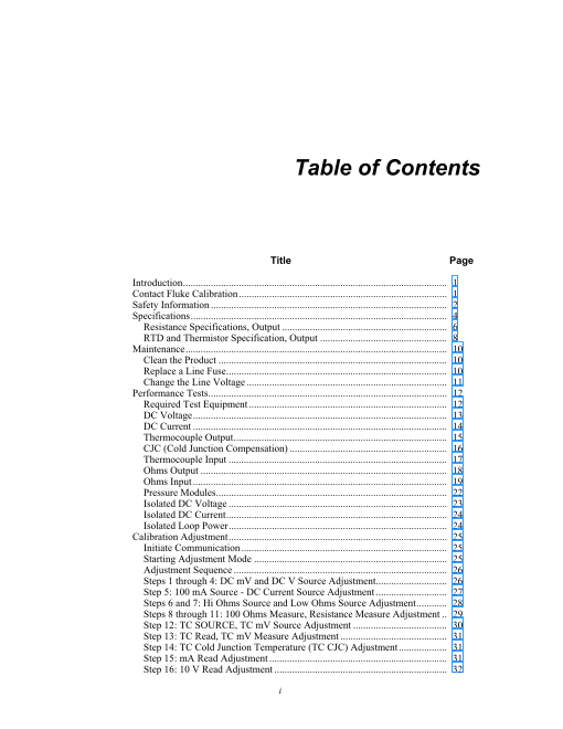
Table of Contents
Table of Contents
Title Page
Introduction ........................................................................................................ 1
Contact Fluke Calibration .................................................................................. 1
Safety Information ............................................................................................. 2
Specifications ..................................................................................................... 4
Resistance Specifications, Output ................................................................. 6
RTD and Thermistor Specification, Output .................................................. 8
Maintenance ....................................................................................................... 10
Clean the Product .......................................................................................... 10
Replace a Line Fuse ....................................................................................... 10
Change the Line Voltage ............................................................................... 11
Performance Tests .............................................................................................. 12
Required Test Equipment .............................................................................. 12
DC Voltage .................................................................................................... 13
DC Current .................................................................................................... 14
Thermocouple Output .................................................................................... 15
CJC (Cold Junction Compensation) .............................................................. 16
Thermocouple Input ...................................................................................... 17
Ohms Output ................................................................................................. 18
Ohms Input .................................................................................................... 19
Pressure Modules ........................................................................................... 22
Isolated DC Voltage ...................................................................................... 23
Isolated DC Current ....................................................................................... 24
Isolated Loop Power ...................................................................................... 24
Calibration Adjustment ...................................................................................... 25
Initiate Communication ................................................................................. 25
Starting Adjustment Mode ............................................................................ 25
Adjustment Sequence .................................................................................... 26
Steps 1 through 4: DC mV and DC V Source Adjustment ............................ 26
Step 5: 100 mA Source - DC Current Source Adjustment ............................ 27
Steps 6 and 7: Hi Ohms Source and Low Ohms Source Adjustment ............ 28
Steps 8 through 11: 100 Ohms Measure, Resistance Measure Adjustment .. 29
Step 12: TC SOURCE, TC mV Source Adjustment ..................................... 30
Step 13: TC Read, TC mV Measure Adjustment .......................................... 31
Step 14: TC Cold Junction Temperature (TC CJC) Adjustment ................... 31
Step 15: mA Read Adjustment ...................................................................... 31
Step 16: 10 V Read Adjustment .................................................................... 32
i
Page4
7526A
Calibration Manual
Step 17: 100 V Read Adjustment .................................................................. 33
User-Replaceable Parts ...................................................................................... 34
Accessories ........................................................................................................ 36
ii
Page5
List of Tables
List of Tables
Table Title Page
1. Symbols .................................................................................................................. 3
2. Replacement Fuses ................................................................................................. 10
3. Required Equipment ............................................................................................... 12
4. DC Voltage Verification ........................................................................................ 13
5. DC Current Verification ......................................................................................... 14
6. TC mV Test ............................................................................................................ 15
7. Ohms Output Ranges ............................................................................................. 18
8. Ohms Ratio Table .................................................................................................. 20
9. Isolated DC Voltage ............................................................................................... 23
10. Isolated DC Current ............................................................................................... 24
11. User-Replaceable Parts .......................................................................................... 34
12. Accessories ............................................................................................................. 36
iii
Page6
7526A
Calibration Manual
iv
Page7
List of Figures
List of Figures
Figure Title Page
1. Replace the Line Fuse ............................................................................................ 11
2. DC Current Performance Test Connections ........................................................... 14
3. Thermocouple Output Performance Test Connections .......................................... 15
4. CJC Performance Test Connections ....................................................................... 16
5. TC Input Performance Test Connections ............................................................... 17
6. Resistance Output Performance Test Connections ................................................ 18
7. Ohms Input Performance Test Connections ........................................................... 19
8. Ohms Measurement Performance Test Connections ............................................. 21
9. Pressure Module Performance Test Connections ................................................... 22
10. Isolated DC Voltage Performance Test Connections ............................................. 23
11. Isolated DC Current Performance Test Connections ............................................. 24
12. DC Volts Source Performance Test Connections .................................................. 27
13. High and Low Ohms Adjustment Connections ...................................................... 27
14. Hi Ohms Source and Low Ohms Source Adjustment Connections ....................... 28
15. 100 Ohms Measure, Resistance Measurement Adjustment Connections .............. 29
16. mA Read Adjustment Connections ........................................................................ 32
17. 10 V Read Adjustment Connections ...................................................................... 33
18. User-Replaceable Parts .......................................................................................... 35
v
Page8
7526A
Calibration Manual
vi
Page9
Introduction、Contact Fluke Calibration
Introduction
Warning
To prevent possible electrical shock, fire, or personal injury,
read all safety information before you use the Product.
This manual contains the verification and calibration adjustment procedures for the
7526A Precision Process Calibrator (the Product). Please see the 7526A Users Manual
for usage information.
The Product is an accurate, full-featured temperature, pressure, and dc calibrator. It is
meant for research and development, manufacturing, and calibration laboratory
procedures.
Contact Fluke Calibration
To contact Fluke Calibration, call one of the subsequent telephone numbers:
• Technical Support USA: 1-877-355-3225
• Calibration/Repair USA: 1-877-355-3225
• Canada: 1-800-36-FLUKE (1-800-363-5853)
• Europe: +31-40-2675-200
• Japan: +81-3-6714-3114
• Singapore: +65-6799-5566
• China: +86-400-810-3435
• Brazil: +55-11-3759-7600
• Anywhere in the world: +1-425-446-6110
To see product information and download the latest manual supplements, visit Fluke
Calibration’s website at www.flukecal.com.
To register your product, visit http://flukecal.com/register-product.
1
Page10
Safety Information
7526A
Calibration Manual
Safety Information
A Warning identifies conditions and procedures that are dangerous to the user. A
Caution identifies conditions and procedures that can cause damage to the Product or
the equipment under test.
Warnings
To prevent possible electrical shock, fire, or personal injury:
• Read all safety Information before you use the Product.
• Carefully read all instructions.
• Use the Product only as specified, or the protection
supplied by the Product can be compromised.
• Use this Product indoors only.
• Examine the case before you use the Product. Look for
cracks or missing plastic. Carefully look at the insulation
around the terminals.
• Use only the mains power cord and connector approved for
the voltage and plug configuration in your country and rated
for the Product.
• Replace the mains power cord if the insulation is damaged
or if the insulation shows signs of wear.
• Make sure the ground conductor in the mains power cord is
connected to a protective earth ground. Disruption of the
protective earth could put voltage on the chassis that could
cause death.
• Do not put the Product where access to the mains power
cord is blocked.
• Do not touch voltages >30 V ac rms, 42 V ac peak, or
60 V dc.
• Use only cables with correct voltage ratings.
• Do not apply more than the rated voltage, between the
terminals or between each terminal and earth ground.
• Do not use the Product around explosive gas, vapor, or in
damp or wet environments.
• Remove all probes, test leads, and accessories that are not
necessary for the measurement.
• Do not use the Product if it operates incorrectly.
• Do not use and disable the Product if it is damaged.
2
Page11
Precision Process Calibrator
Safety Information
Table 1 shows the symbols used on the Product and in this manual.
Table 1. Symbols
Symbol Definition Symbol Definition
This product complies with the WEEE
Directive (2002/96/EC) marking
requirements. The affixed label
indicates that you must not discard this
electrical/electronic product in domestic
household waste. Product Category:
Risk of Danger. Important information. With reference to the equipment types
See Manual. in the WEEE Directive Annex I, this
product is classed as category 9
"Monitoring and Control
Instrumentation” product. Do not
dispose of this product as unsorted
municipal waste. Go to Fluke’s website
for recycling information.
Hazardous voltage. Risk of electric Fuse
shock.
AC (Alternating Current) Protective Earth Ground
Conforms to European Union
Earth Terminal
directives.
AC (Alternating Current) and DC (Direct DC (Direct Current)
Current)
This product has been tested to the
requirements of CAN/CSA-C22.2 Pressure
No. 61010-1, third edition.
3
Page12
Specifications
7526A
Calibration Manual
Specifications
General Specifications
Warm-up Time ....................................... Twice the time since last warmed up, to a maximum of 30 minutes
Settling Time ......................................... Less than 5 seconds for all functions and ranges except as noted
Standard Interfaces .............................. RS-232
IEEE-488 (GPIB)
Temperature Performance
Operating ........................................ 0 °C to 50 °C
Calibration (tcal) ............................. 18 °C to 28 °C
Storage ........................................... -20 °C to 70 °C
Temperature Coefficient ....................... Temperature coefficient for temperatures outside tcal 5 °C is 10 % of the 90-day
specification (or 1 year if applicable) per °C
Relative Humidity
Operating ........................................ <80 % to 30 °C
<70 % to 40 °C
<40 % to 50 °C
Altitude
Operating .......................................... 3,000 m (9,800 ft) maximum
Non-operating ................................... 12,200 m (40,000 ft) maximum
Safety .................................................... EN/IEC 61010-1, ANSI/ISA 61010-1, CAN/CSA 22.2 No. 61010-1
EMC ........................................................ Complies with EN/IEC 61326-1, EN/IEC 61326-2-1 for controlled EM
environments except when used in the following conditions:
• In electromagnetic fields from 0.08-2.7 GHz in excess of 1V/m.
• When subjected to electrostatic discharge (ESD) to the binding posts. Good
static awareness practices should be followed when handling this product
such as discharging any built up static charge to the product chassis prior to
handling terminals or test connections.
• When the product is used with data I/O cables in excess of 3 m.
Analog Low Isolation ............................ 20 V
Line Power Line Voltage (selectable)
120 V~ ................................................... 100 V to 120 V
240 V~ .................................................... 220 V to 240 V
Line Frequency ..................................... 47 to 63 Hz
Line Voltage Variation .......................... ±10 % about setting
Power Consumption ............................ 15 VA maximum
Dimensions
Height ............................................. 14.6 cm (5.75 inch)
Width ............................................... 44.5 cm (17.5 inch)
Depth .............................................. 29.8 cm (11.75 inch) overall
Weight (without options) ...................... 4.24 kg (9.35 lb)
4
Page13
Precision Process Calibrator
Specifications
DC Voltage Specifications, Output
Absolute Uncertainty, tcal ±5°C,
Stability
[1] ±(ppm of output +µV)
Ranges Resolution Maximum
° Burden [2]
24 hours, ±1 C
90 Days 1 Year
±(ppm of output +μV)
0 mV to 100.000 mV 25 3 30 3 5 ppm + 2 μV 1 μV 10 mA
0 V to 1.00000 V 25 10 30 10 4 ppm + 10 μV 10 μV 10 mA
0 V to 10.0000 V 25 100 30 100 4 ppm + 100 μV 100 μV 10 mA
0 V to 100.000 V 25 1 mV 30 1 mV 5 ppm + 1 mV 1 mV 1 mA
[1] All outputs are positive only, unless otherwise noted.
[2] Remote sensing is not provided. Output resistance is < 1Ω.
Noise
Bandwidth 0.1 to 10 Hz p-p Bandwidth 10 Hz to
Ranges ±(ppm of output +µV) 10 kHz rms µV
0 mV to 100.000 mV 1 μV 6 μV
0 V to 1.00000 V 10 μV 60 μV
0 V to 10.0000 V 100 μV 600 μV
0 V to 100.000 V 10 ppm+1 mV 20 mV
DC Voltage Specifications, Thermocouple Jack, Input and Output
Absolute Uncertainty, tcal ±5°C,
Stability
[1] ±(ppm of output +µV)
Ranges Resolution Maximum
[2]
24 hours, ±1 °C Burden
90 Days 1 Year
±(ppm of output +μV)
-10 to 75.000 mV 25 2 μV 30 2 μV 5 ppm + 2 μV 1 μV 10 Ω
[1] All outputs are positive only, unless otherwise noted.
[2] Remote sensing is not provided. Output resistance is < 1Ω.
DC Voltage Specifications, Isolated Input
Absolute Uncertainty, tcal ±5 °C,
Ranges Resolution
±(ppm of reading + mV)
0 V to 10.0000 V 50 0.2 100 μV
0 V to 100.000 V 50 2.0 1 mV
DC Current Specifications, Output
Absolute Uncertainty, tcal ±5 °C, Maximum Maximum
Ranges [1] ± (ppm of output + µA) Resolution Compliance Inductive
90 Days 1 Year Voltage Load
0 mA to 100.000 mA 40 [2] 1 50 [2] 1 1 μA 12 V 100 mH
[1] All outputs are positive only.
[2] For line voltages less than 95 V (±100 ppm of reading)
Noise
Ranges
Bandwidth 0.1 to 10 Hz p-p Bandwidth 10 Hz to 10 kHz rms μV
0 mA to 100.000 mA 2000 nA 20 μA
DC Current Specifications, Isolated Input
Absolute Uncertainty, tcal ±5 °C,
Ranges Resolution
±(ppm of reading + μA)
0 mA to 50.0000 mA 100 1 0.1 μA
0 mA to 24.0000 mA (Loop Power) [1][2] 100 1 0.1 μA
[1] Loop Power: 24 V ±10 %
[2] HART Resistor: 250 Ω ±3 %
5
Page14
Resistance Specifications, Output
7526A
Calibration Manual
Resistance Specifications, Output
Absolute Uncertainty,
Ranges tcal ±5 °C, ± Ohms Resolution Nominal Current [1]
90 Days 1 Year
5 Ω to 400.000 Ω 0.012 0.015 0.001 Ω 1 to 3 mA
5 Ω to 4.00000 kΩ 0.25 0.3 0.01 Ω 100 μA to 1 mA
[1] For currents lower than shown, the specification becomes
New Spec. = Stated Spec. x Imin/Iactual.
For example, a 500 μA stimulus that measures 100 Ω has a specification of: 0.015 Ω x 1 mA/500 μA=0.03 Ω
Resistance Specifications, Input
Absolute Uncertainty, tcal ±5 °C
Ranges ±(ppm of reading + Ω) Resolution Stimulus Current
90 Days 1 Year
0 Ω to 400.000 Ω ±20 ppm + 0.0035 Ω ±20 ppm + 0.004 Ω 0.001 Ω 1 mA
0 Ω to 4.00000 kΩ ±20 ppm + 0.035 Ω ±20 ppm + 0.04 Ω 0.01 Ω 0.1 mA
Thermocouple Specification, Output and Input
Absolute Uncertainty, tcal ±5 °C, ±(°C) [1]
Range (°C)
TC Type Output/Input
Minimum Maximum 90 days 1 Year
600 °C 800 °C 0.35 °C 0.35 °C
B 800 °C 1550 °C 0.28 °C 0.28 °C
1550 °C 1820 °C 0.21 °C 0.22 °C
0 °C 1000 °C 0.15 °C 0.16 °C
1000 °C 1800 °C 0.22 °C 0.23 °C
C 1800 °C 2000 °C 0.24 °C 0.26 °C
2000 °C 2316 °C 0.32 °C 0.35 °C
-250 °C -200 °C 0.24 °C 0.25 °C
-200 °C -100 °C 0.10 °C 0.12 °C
E -100 °C 0 °C 0.07 °C 0.09 °C
0 °C 600 °C 0.06 °C 0.08 °C
600 °C 1000 °C 0.08 °C 0.10 °C
-210 °C -100 °C 0.13 °C 0.14 °C
J -100 °C 800 °C 0.07 °C 0.09 °C
800 °C 1200 °C 0.08 °C 0.10 °C
-250 °C -200 °C 0.45 °C 0.46 °C
-200 °C -100 °C 0.15 °C 0.16 °C
K -100 °C 500 °C 0.08 °C 0.10 °C
500 °C 800 °C 0.09 °C 0.10 °C
800 °C 1372 °C 0.11 °C 0.13 °C
-200 °C -100 °C 0.08 °C 0.10 °C
L
-100 °C 900 °C 0.07 °C 0.09 °C
-250 °C -200 °C 0.72 °C 0.73 °C
-200 °C -100 °C 0.22 °C 0.23 °C
-100 °C 0 °C 0.11 °C 0.12 °C
N 0 °C 100 °C 0.09 °C 0.11 °C
100 °C 800 °C 0.08 °C 0.10 °C
800 °C 1300 °C 0.10 °C 0.12 °C
6
Page15
Precision Process Calibrator
Specifications
Absolute Uncertainty, tcal ±5 °C, ±(°C) [1]
Range (°C)
TC Type Output/Input
Minimum Maximum 90 days 1 Year
-50 °C -25 °C 0.54 °C 0.55 °C
-25 °C 0 °C 0.44 °C 0.45 °C
0 °C 100 °C 0.38 °C 0.39 °C
100 °C 400 °C 0.27 °C 0.28 °C
R 400 °C 600 °C 0.21 °C 0.22 °C
600 °C 1000 °C 0.19 °C 0.21 °C
1000 °C 1600 °C 0.18 °C 0.19 °C
1600 °C 1767 °C 0.21 °C 0.23 °C
-50 °C -25 °C 0.51 °C 0.51 °C
-25 °C 0 °C 0.43 °C 0.43 °C
0 °C 100 °C 0.37 °C 0.38 °C
100 °C 400 °C 0.28 °C 0.29 °C
S 400 °C 600 °C 0.22 °C 0.23 °C
600 °C 1000 °C 0.21 °C 0.22 °C
1000 °C 1600 °C 0.20 °C 0.22 °C
1600 °C 1767 °C 0.24 °C 0.26 °C
-250 °C -200 °C 0.34 °C 0.35 °C
-200 °C -100 °C 0.14 °C 0.16 °C
T -100 °C 0 °C 0.09 °C 0.11 °C
0 °C 200 °C 0.07 °C 0.09 °C
200 °C 400 °C 0.06 °C 0.09 °C
-200 °C 0 °C 0.15 °C 0.16 °C
U 0 °C 200 °C 0.08 °C 0.10 °C
200 °C 600 °C 0.07 °C 0.10 °C
-200 °C -100 °C 0.10 °C 0.11 °C
-100 °C 0 °C 0.07 °C 0.09 °C
XK 0 °C 600 °C 0.06 °C 0.08 °C
600 °C 800 °C 0.07 °C 0.09 °C
0 °C 200 °C 0.17 °C 0.18°C
200 °C 600 °C 0.14 °C 0.16 °C
600 °C 800 °C 0.15 °C 0.17 °C
BP 800 °C 1600 °C 0.22 °C 0.23 °C
1600 °C 2000 °C 0.26 °C 0.28 °C
2000 °C 2500 °C 0.38 °C 0.40 °C
[1] Does not include thermocouple wire error.
Type B, E, J ,K, N, R, S and T are based on ITS-90
Type L and U are based on DIN 43710-1985
Type C is based on ASTM standard E 988-96
Type XK and BP are based on GOST R 8.585-2001
7
Page16
RTD and Thermistor Specification, Output
7526A
Calibration Manual
RTD and Thermistor Specification, Output
Range °C Absolute Uncertainty, tcal ±5 °C ±(°C) [1]
RTD Types
Minimum Maximum 90 Days 1 Year
Pt 385, 100 Ω -200 °C 800 °C 0.04 °C 0.05 °C
Pt 3926, 100 Ω -200 °C 630 °C 0.04 °C 0.05 °C
Pt 3916, 100 Ω -200 °C 630 °C 0.04 °C 0.05 °C
-200 °C 400 °C 0.35 °C 0.40 °C
Pt 385, 200 Ω
400 °C 630 °C 0.42 °C 0.50 °C
Pt 385, 500 Ω -200 °C 630 °C 0.15 °C 0.17 °C
Pt 385, 1000 Ω -200 °C 630 °C 0.07 °C 0.09 °C
Ni 120, 120 Ω -80 °C 260 °C 0.02 °C 0.02 °C
Cu 427, 10 Ω [2] -100 °C 260 °C 0.30 °C 0.38 °C
YSI 400 15 °C 50 °C 0.005 °C 0.007 °C
[1] 2-wire output
[2] Based on MINCO Application Aid No. 18
RTD and Thermistor Specification, Input
Absolute Uncertainty, tcal ±5 °C, ±(°C) [1]
Range (°C)
RTD Type
Output/Input
Minimum Maximum 90 Days 1 Year
-200 °C -80 °C 0.012 °C 0.013 °C
-80 °C 100 °C 0.018 °C 0.020 °C
100 °C 300 °C 0.022 °C 0.024 °C
Pt 385, 100 Ω 300 °C 400 °C 0.025 °C 0.026 °C
400 °C 630 °C 0.031 °C 0.033 °C
630 °C 800 °C 0.037 °C 0.038 °C
-200 °C -80 °C 0.012 °C 0.013 °C
-80 °C 0 °C 0.014 °C 0.015 °C
0 °C 100 °C 0.016 °C 0.017 °C
Pt 3926, 100 Ω 100 °C 300 °C 0.022 °C 0.022 °C
300 °C 400 °C 0.022 °C 0.026 °C
400 °C 630 °C 0.024 °C 0.032 °C
-200 °C -190 °C 0.009 °C 0.010 °C
-190 °C -80 °C 0.012 °C 0.013 °C
-80 °C 0 °C 0.014 °C 0.015 °C
0 °C 100 °C 0.016 °C 0.017 °C
Pt 3916, 100 Ω 100 °C 300 °C 0.021 °C 0.022 °C
300 °C 400 °C 0.024 °C 0.026 °C
400 °C 600 °C 0.030 °C 0.031 °C
600 °C 630 °C 0.031 °C 0.033 °C
-200 °C -80 °C 0.047 °C 0.053 °C
-80 °C 0 °C 0.050 °C 0.056 °C
0 °C 100 °C 0.053 °C 0.060 °C
Pt 385, 200 Ω 100 °C 260 °C 0.054 °C 0.060 °C
260 °C 300 °C 0.062 °C 0.069 °C
300 °C 400 °C 0.064 °C 0.071 °C
400 °C 630 °C 0.079 °C 0.088 °C
-200 °C 0 °C 0.023 °C 0.025 °C
0 °C 100 °C 0.026 °C 0.028 °C
Pt 385, 500 Ω 100 °C 300 °C 0.031 °C 0.034 °C
300 °C 400 °C 0.035 °C 0.038 °C
400 °C 630 °C 0.041 °C 0.045 °C
8
Page17
Precision Process Calibrator
Specifications
Absolute Uncertainty, tcal ±5 °C, ±(°C) [1]
Range (°C)
RTD Type
Output/Input
Minimum Maximum 90 Days 1 Year
-200 °C 0 °C 0.014 °C 0.015 °C
0 °C 100 °C 0.017 °C 0.018 °C
Pt 385, 1000 Ω 100 °C 300 °C 0.022 °C 0.024 °C
300 °C 400 °C 0.024 °C 0.026 °C
400 °C 630 °C 0.031 °C 0.033 °C
Ni 120, 120 Ω -80 °C 260 °C 0.008 °C 0.009 °C
Cu 427, 10 Ω [2] -100 °C 260 °C 0.097 °C 0.110 °C
YSI 400 15 °C 50 °C 0.005 °C 0.007 °C
SPRT -200 °C 660 °C 0.05 °C 0.06 °C
[1] 4-wire mode. Uncertainties shown do not include probe uncertainties.
[2] Based on MINCO Application Aid No. 18.
Pressure Measurement Specifications
The Calibrator can accept the Fluke 700 or 525A-P Series pressure modules. Pressure modules connect directly into the
front panel Lemo connector with the Calibrator firmware auto-detecting the type and value of the module you connect.
Range Accuracy and Resolution Units
Determined by the pressure module Determined by the pressure module PSI (pounds per square inch)
in H2O 4 °C (inches of water at 4
degrees Celsius)
in H2O 20 °C (inches of water at 20
degrees Celsius)
in H2O 60 °C (inches of water at 60
degrees Fahrenheit)
cm H2O 4 °C (centimeters of water
at 4 degrees Celsius)
cm H2O 20 °C (centimeters of
water at 20 degrees Celsius)
mm H2O 4 °C (millimeters of water
at 4 degrees Celsius)
mm H2O 20 °C (millimeters of
water at 20 degrees Celsius)
BAR (bars)
mBAR (millibars)
kPa (kilopascals)
MPa (megapascals)
in HG 0 °C (inches of mercury at 0
degrees Celsius)
mm HG 0 °C (millimeters of
mercury at 0 degrees Celsius)
kg/cm2 (kilograms per square
centimeter)
Switch Test Specifications, Isolated Input
Contact Closure Resistance <1 kΩ
Excitation Current 27 mA Max
9
Page18
Maintenance、Clean the Product、Replace a Line Fuse
7526A
Calibration Manual
Maintenance
This section explains typical maintenance and tasks necessary to keep the Product in
service.
Warnings
To prevent possible electrical shock, fire, or personal injury:
• Have an approved technician repair the Product.
• Disconnect the mains power cord before you remove the
Product covers.
• Do not operate the Product with covers removed or the case
open. Hazardous voltage exposure is possible.
• Use only specified replacement parts.
Clean the Product
Clean the Product and pressure modules with a soft cloth dampened with water, or mild
soap and water.
Replace a Line Fuse
The line power fuses and line voltage selector are found in the compartment above the
power switch on the right rear side of the Product. Table shows the correct replacement
fuse for each line voltage setting.
Table 2. Replacement Fuses
Fuse Description Line Voltage Setting
0.25 A/250 V (SB) 120 V (Operating Range 90 V to 132 V)
0.125 A/250 V (SB) 240 V (Operating Range 198 V to 264 V)
To ensure safety, use exact replacement only.
To examine or replace a fuse:
1. Disconnect the mains power.
2. Use a flat-head screwdriver to pry up the tab at the base of the line fuse compartment.
Insert the blade into the center slot under the tab. The compartment cover will come
part way out. See Figure 1.
3. Remove the compartment cover. The fuses come out with the compartment cover and
can be examined or replaced.
4. To install the fuse holder, push the compartment cover back into the compartment
until the tab locks in position.
10
Page19
Change the Line Voltage
Precision Process Calibrator
Maintenance
I
o
Changing Line Fuse
gxm009.eps
Figure 1. Replace the Line Fuse
Change the Line Voltage
The Product comes from the factory configured for the line voltage applicable for the
country of purchase, or as specified when it is ordered. To verify the line voltage setting,
examine the line voltage indicator on the power line fuse compartment cover.
Make sure that the line voltage selection is set for 120 V for line voltages between 100 V
and 120 V ±10 % about setting. The selector must be set to 240 V for line voltages
between 220 V and 240 V ±10 % about setting.
11
Page20
Performance Tests、Required Test Equipment
7526A
Calibration Manual
Performance Tests
Warning
To prevent possible electrical shock, fire, or personal injury, do
not perform the performance test procedures unless the
Product is fully assembled.
The performance tests verify the complete operation of the Product and measure the
accuracy of each function against Product specifications. If the Product fails a part of the
test, calibration adjustment or repair is necessary. See “Calibration Adjustment”.
Required Test Equipment
The equipment listed in Table 3 is necessary to do the performance tests and calibration
adjustment.
Table 3. Required Equipment
Equipment Recommended Model Where Used
8-1/2 digit Precision Digital
Fluke 8508A DC volts, dc current, resistance
Multimeter (DMM)
Low ohms measure and SPRT
Ohms shorting block calibration and high ohms
measure calibration
1 Ω Resistance Standard Fluke 742A-1 DC current
Resistance standard, 10 Ω Fluke 742A-10 100 mA source calibration
Ω Low ohms measure and SPRT
Resistance standard, 100 Fluke 742A-100
calibration
1 KΩ Resistance Standard Fluke 742A-1K Resistance
10 KΩ Resistance Standard Fluke 742A-10K Resistance
Multifunction Calibrator Fluke 5522A DC volts, dc current, resistance
Thermistor probe Fluke5640-D TC CJC calibration
Omega E-type thermocouple
Thermocouple probe TC CJC calibration
probe
Pressure Module Any Fluke 700 Series Module Pressure
Lead Set 5520A-525A/LEADS Leads Kit Necessary test cables
Precision Thermistor Fluke 5640-D Temperature
Thermometer Readout Fluke 1504 Temperature
Dewar Flask with Lid - - - Thermocouple
Characterized Type E
- - - Thermocouple
Thermocouple
Banana Jack to Copper TC Mini-
- - - Thermocouple
connector
Lag bath TC CJC calibration
12