


一般鋼材・耐熱合金向け高能率4枚刃スクエアエンドミル『MSCZ440/MSUSZ440』、炭素鋼やアルミ、ステンレスなど延性の高い被削材へ特化したフラットドリル『MFD』、切削抵抗を低減する特殊刃形状を採用したねじ切り工具『MMTM・MMTU・MMTS』のご案内。PR動画にて加工事例も是非ご覧ください。
関連メディア
このカタログについて
| ドキュメント名 | 【新製品】高能率4枚刃スクエア/極小径フラットドリル/特殊刃形状スレッドミルのご案内【部品加工】 |
|---|---|
| ドキュメント種別 | 製品カタログ |
| ファイルサイズ | 20.4Mb |
| 取り扱い企業 | 日進工具株式会社 (この企業の取り扱いカタログ一覧) |
この企業の関連カタログ


このカタログの内容
Page1
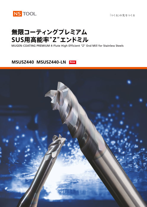
無限コーティングプレミアム
SUS用高能率“Z”エンドミル
MUGEN-COATING PREMIUM 4-Flute High Efficient "Z" End Mill for Stainless Steels
MSUSZ440 MSUSZ440-LN New
〒140-0014 東京都品川区大井 1-28-1 住友不動産大井町駅前ビル6F
TEL. 03-3774-2459 FAX. 03-3774-2460
19’10
Page2
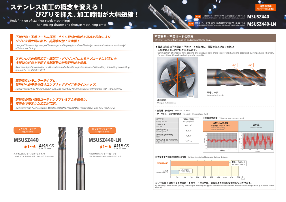
ステンレス加工の概念を変える! 特許申請中PATENTPENDING
びびりを抑え、加工時間が大幅短縮! New 無限コーティングプレミアムSUS用高能率”Z”エンドミル
MUGEN-COATING PREMIUM 4-Flute High Efficient “Z” End Mill for Stainless Steels MSUSZ440
Redefinition of stainless steels machining!
無限コーティングプレミアムSUS用高能率”Z”ロングネックエンドミル
Minimizing chatter and shorten machining time! New MUGEN-COATING PREMIUM 4-Flute Long Neck High Efficient “Z” End Mill for Stainless Steels MSUSZ440-LN
不等分割・不等リードの採用、さらに刃部の剛性を高めた設計により、 不等分割・不等リードの効果
1 びびりを最大限に抑え、高能率な加工を実現!
Effect of unequal flute spacing and unequal helix angle
Unequal flute spacing, unequal helix angle and high rigid end profile design to minimize chatter realize high
efficient machining. ◦最適な角度の不等分割・不等リードを採用し、共振を抑えびびりを防止! 工具寿命と加工面品位が向上します。
O ptimization of unequal flute spacing and unequal helix angle to prevent chattering produced by sympathetic vibration.
Enhanced tool life and machining surface quality.
ステンレスの側面加工・溝加工・ドリリングによるアプローチに対応した
2 多機能な性能を実現する新開発の特殊刃形状を採用。 40° 42°
New developed special edge profile realized multi-functional performance of side milling, slot milling and drilling
approaches on stainless steel. β°
α°
高剛性なレギュラータイプと、 α°
3 被削材への干渉を防ぐロングネックタイプをラインナップ。 β°
Lineup regular type for high rigidity and long neck type for prevention of interference with work material.
不等リード
Unequal helix angle
1000μm
耐熱性の高い無限コーティングプレミアムを採用し、 不等分割
4 長寿命で安定した加工が可能。 Unequal flute spacing
Optimized high heat-resistance MUGEN-COATING PREMIUM to realize stable long time machining.
・被削材:SUS304 Material:SUS304
・クーラント:水溶性切削油 Coolant:Water soluble fluid
加工工程 荒取り(側面) ①振動測定結果 Vibration measurement result
Cutting process Roughing (Side)
工具サイズ MSUSZ440 従来品
Tool size φ6×12 不等分割・不等リード形状
レギュラータイプ ロングネックタイプ Unequal flute spacing Conventional tool回転数 [min-1] 5,500 Unequal helix angleRegular type Long neck type Spindle speed
送り速度 [mm/min]
Feed 1,300
MSUSZ440 MSUSZ440-LN 切り込み量 ap×ae [mm]Depth of cut 12×1.2
φ1~6 全62サイズTotal 62 sizes φ1~6 全33サイズTotal 33 sizes
刃長は刃径の2倍・3倍(一部サイズ) 有効長は刃径の3 倍・4 倍・5 倍
Length of cut lined up with L/D=2 or 3 (Some sizes). Effective length lined up with L/D=3 to 5. ②折損までの加工時間(加工距離) Cutting time to tool breakage (Cutting distance)
MSUSZ440 430分(559m)430min (559m)
従来品 60分(78m)
Conventional tool 60min (78m)
0 50 100 150 200 250 300 350 400 450 500 (分)
(min)
びびり振動を抑制する不等分割・不等リードの採用が、面質向上と寿命の安定性につながります。
By adopting unequal flute spacing and unequal helix angle suppress chatter vibration leads to improved machining surface quality and stable
tool life.
Page3
特許申請中
PATENTPENDING
New 無限コーティングプレミアムSUS用高能率”Z”エンドミル
MUGEN-COATING PREMIUM 4-Flute High Efficient “Z” End Mill for Stainless Steels MSUSZ440
New 無限コーティングプレミアムSUS用高能率”Z”ロングネックエンドミル
MUGEN-COATING PREMIUM 4-Flute Long Neck High Efficient “Z” End Mill for Stainless Steels MSUSZ440-LN
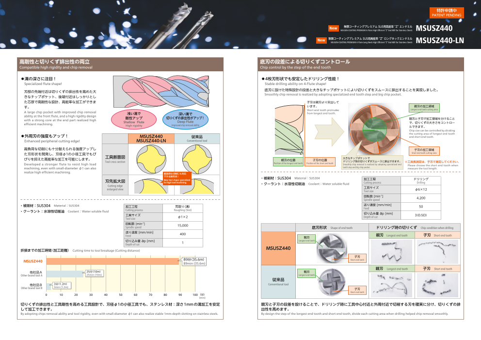
高剛性と切りくず排出性の両立 底刃の段差による切りくずコントロール
Compatible high rigidity and chip removal Chip control by the step of the end tooth
◦溝の深さに注目! ◦4枚刃形状でも安定したドリリング性能!
Specialized flute shape! Stable drilling ability on 4-Flute shape!
刃部の先端付近は切りくずの排出性を高めた大 底刃に設けた特殊設計の段差と大きなチップポケットにより切りくずをスムースに排出することを実現しました。
きなチップポケット、後端付近はしっかりとし Smoothly chip removal is realized by adopting specialized end tooth step and big chip pocket.
た芯厚で高剛性な設計、高能率な加工ができま 子刃は親刃より突出して
す。 います。 親刃の加工領域
Short end tooth protrudes Longest end tooth cutting area
A large chip pocket with improved chip removal 浅い溝で 深い溝で from longest end tooth.
ability at the front flute, and a high rigidity design 剛性アップ 切りくずの排出性がアップ!with a strong core at the end part realized high 親刃と子刃で加工領域を分けることShallow Flute Deep Flute
efficient machining. で、切りくずの大きさをコントローHigh rigidity Improved chip removal ability ルできます。
Chip size can be controlled by dividing
◦外周刃の強度もアップ! the cutting area of longest end tooth MSUSZ440 従来品 and short end tooth.
Enhanced peripheral cutting edge! MSUSZ440-LN Conventional tool
高負荷な切削にも十分耐えられる強度アップし 子刃の加工領域
た刃形状を開発し、刃径φ1の小径工具でもび Short end tooth cutting area
びりを抑えた高能率な加工を可能にします。 工具断面図 親刃の位置 子刃の位置 大きなチップポケットでTool cross section ドリリング時の切りくずがスムースに排出できます。Position of the longest end tooth Position of the short end tooth ※工具長測定は、子刃で測定してください。Developed a stronger flute to resist high load Smoothly chip removal is realized by adopting specialized end Please choose the short end tooth when
machining, even with small-diameter φ1 can also tooth step and big chip pocket. measure the tool length.
realize high efficient machining. 高負荷な切削にも対応
できる新形状! ・被削材:SUS304 Material:SUS304
刃先拡大図 New tool shape specialized 加工工程 ドリリングfor high load machining. ・クーラント:水溶性切削油 Coolant:Water soluble fluid Cutting process DrillingCutting edge
enlarged view 工具サイズ
Tool size φ6×12
回転数 [min-1]
Spindle speed 4,200
・被削材:SUS304 Material:SUS304 加工工程 荒取り(溝) 送り速度 [mm/min]Feed 50
・クーラント:水溶性切削油 Coolant:Water soluble fluid Cutting process Roughing (Slot)
工具サイズ 切り込み量 ap [mm]
Tool size φ1×2 Depth of cut
3(0.5D)
回転数 [min-1]
Spindle speed 15,000 底刃形状 Shape of end tooth ドリリング時の切りくず Chip condition when drilling
送り速度 [mm/min]
Feed 400 親刃 親刃 Longest end tooth 子刃 Short end tooth
切り込み量 ap [mm] Longest end tooth
Depth of cut 1
折損までの加工時間(加工距離) Cutting time to tool breakage (Cutting distance) MSUSZ440
子刃
MSUSZ440 89分(35.6m) Short end tooth
89min (35.6m)
親刃 Longest end tooth 子刃 Short end tooth
他社品A 25分(10m) 親刃
Other brand tool A 25min (10m) Longest end tooth
従来品
他社品B 3分(1.2m) Conventional tool
Other brand tool B 3min (1.2m) 子刃
Short end tooth
0 10 20 30 40 50 60 70 80 90 100 (分)
(min)
切りくずの排出性と工具剛性を高める工具設計で、刃径φ1の小径工具でも、ステンレス材:深さ1mmの溝加工を安定 親刃と子刃の段差を設けることで、ドリリング時に工具中心付近と外周付近で切削する刃を確実に分け、切りくずの排
して加工できます。 出性を高めます。
By adopting chips removal ability and tool rigidity, even with small-diameter φ1 can also realize stable 1mm-depth slotting on stainless steels. By design the step of the longest end tooth and short end tooth, divide each cutting area when drilling helped chip removal smoothly.
Page4
MSUSZ440 New MSUSZ440
無限コーティングプレミアムSUS用高能率”Z”エンドミル
MUGEN-COATING PREMIUM 4-Flute High Efficient “Z” End Mill for Stainless Steels 切削条件参考表 Recommended Milling Conditions
γ° 被削材 ステンレス鋼 チタン合金Stainless Steels Titanium Alloy
Work Material SUS304 Ti-6Al-4V
ℓ※1 側面 溝 ドリリング 側面 溝 ドリリング
刃径と Side Milling Slotting Drilling Side Milling Slotting Drilling
L 刃 径 刃 長 刃長の
Length of 比L/D 回転数 送り速度 回転数 送り速度 回転数 送り速度 回転数 送り速度 回転数 送り速度 回転数 送り速度Dia. Cut Spindle Speed Feed Spindle Speed Feed Spindle Speed Feed Spindle Speed Feed Spindle Speed Feed Spindle Speed Feed
●不等分割・不等リードの採用、さらに刃部の剛性を高めた設計により、びびりを最大限に抑え、 ※ 1 刃長は、規格表の数値に対し0.1mm 長くしております。 L/D
高能率な加工を実現! The practical Length of Cut is 0.1mm longer than the specification min-1 mm/min min-1 mm/min min-1 mm/min min-1 mm/min min-1 mm/min min-1 mm/min
●ステンレスの側面加工・溝加工・ドリリングによるアプローチに対応した多機能な性能を実 table.
現する新開発の特殊刃形状を採用。 ※ 2 シ ャンク公差はJIS規格でh4となりますが、当社では-0.001mm~-0.003mm 2 2 18,000 600 15,000 200 15,000 50 16,800 600 13,500 200 13,500 50
●耐熱性の高い無限コーティングプレミアムを採用し、長寿命で安定した加工が可能。 の範囲[0.002mm]で生産しております。
1
3 3 16,000 500 12,000 150 12,000 30 14,900 500 10,800 150 10,800 30
●全62サイズ、刃長が刃径の2倍と3倍(一部サイズ)をラインナップ。 Shank tolerance is h4(JIS), NS TOOL produces within 0.002mm from -0.001mm~-0.003mm.
●Unequal flute spacing, unequal helix angle and high rigid end profile design to minimize chatter 3 2 12,500 700 11,000 220 11,000 50 11,700 700 10,000 220 10,000 50 1.5
realize high efficient machining. 4.5 3 11,000 550 8,500 160 8,500 30 10,300 550 7,700 160 7,700 30
●New developed special edge profile realized multi-functional performance of side milling, slot
milling and drilling approaches on stainless steel. 4 2 10,000 850 8,600 240 8,600 50 9,300 850 7,800 240 7,800 50
●Optimized high heat-resistance MUGEN-COATING PREMIUM to realize stable long time machining. 2
●Total 62 sizes, some sizes line up with L/D=2 or 3. 被削材 Work Material 6 3 8,500 650 7,300 180 7,300 30 7,900 650 6,600 180 6,600 30
ステンレス鋼 チタン合金 5 2 8,200 1,000 7,600 280 7,600 50 7,600 1,000 6,900 280 6,900 50
Stainless Steels Titanium Alloy 2.5
◎ ○ 7.5 3 7,100 750 6,300 200 6,300 30 6,600 750 5,700 200 5,700 30
6 2 7,200 1,100 6,800 300 6,800 50 6,700 1,100 6,200 300 6,200 50
※2019年11月発売 ※Released in November, 2019. 単位[ 寸法 : mm / 価格 : 円] Unit [Size : mm / Retail Price : JPY] 3 9 3 6,000 800 5,400 220 5,400 30 5,600 800 4,900 220 4,900 30
コードNo. (D)刃径 (ℓ)刃長 (γ)首角 (d)シャンク径 (L)全長 標準価格 コードNo. (D)刃径 (ℓ)刃長 (γ)首角 (d)シャンク径 (L)全長 標準価格 7 2 6,700 1,150 5,700 330 5,700 50 6,200 1,150 5,200 330 5,200 50
Code No. Dia. Length of Cut Neck Taper Angle Shank Dia. Overall Length Retail Price Code No. Dia. Length of Cut Neck Taper Angle Shank Dia. Overall Length Retail Price 3.5
10.5 3 5,500 900 4,800 230 4,800 30 5,100 900 4,400 230 4,400 30
08-00152-01020 2 12° 4 50 5,000 08-00152-03520 7 12° 6 50 6,600 8 2 6,400 1,200 5,300 330 5,300 50 6,000 1,200 4,800 330 4,800 50
1 3.5 4
08-00152-01030 3 12° 4 50 5,200 08-00152-03530 10.5 12° 6 60 7,100 12 3 5,400 920 4,400 230 4,400 30 5,000 920 4,000 230 4,000 30
08-00152-01120 1.1 2.2 12° 4 50 6,000 08-00152-03620 3.6 7.2 12° 6 50 6,600 9 2 6,000 1,200 4,900 350 4,900 50 5,600 1,200 4,500 350 4,500 50 4.5
08-00152-01220 1.2 2.4 12° 4 50 6,000 08-00152-03720 3.7 7.4 12° 6 50 6,600 13.5 3 5,200 1,000 4,000 240 4,000 30 4,800 1,000 3,700 240 3,700 30
1.3 2.6 12° 4 50 6,000 3.8 7.6 12° 6 50 6,600 10 2 5,600 1,200 4,600 360 4,600 50 5,200 1,200 4,200 360 4,200 50 08-00152-01320 08-00152-03820 5
15 3 5,000 1,000 3,700 240 3,700 30 4,700 1,000 3,400 240 3,400 30
08-00152-01420 1.4 2.8 12° 4 50 6,000 08-00152-03920 3.9 7.8 12° 6 50 6,600
11 2 5,300 1,200 4,400 380 4,400 50 4,900 1,200 4,000 380 4,000 50
08-00152-01520 3 12° 4 50 6,000 08-00152-04020 8 12° 6 50 6,600 5.5
1.5 4 16.5 3 4,800 1,000 3,400 250 3,400 30 4,500 1,000 3,100 250 3,100 30
08-00152-01530 4.5 12° 4 50 6,400 08-00152-04030 12 12° 6 60 7,000 12 2 5,000 1,200 4,200 400 4,200 50 4,600 1,200 3,800 400 3,800 50
6
08-00152-01620 1.6 3.2 12° 6 50 6,300 08-00152-04120 4.1 8.2 12° 6 50 7,000 18 3 4,500 1,000 3,200 250 3,200 30 4,200 1,000 2,900 250 2,900 30
08-00152-01720 1.7 3.4 12° 6 50 6,300 08-00152-04220 4.2 8.4 12° 6 50 7,000 側面 Side Milling 溝 Slotting 側面 Side Milling 溝 Slotting
08-00152-01820 1.8 3.6 12° 6 50 6,300 08-00152-04320 4.3 8.6 12° 6 50 7,000 刃長 D 刃長 D1D 1D
08-00152-01920 1.9 3.8 12° 6 50 6,300 08-00152-04420 4.4 8.8 12° 6 50 7,000 Length of Cut Length of Cut切り込み量
08-00152-02020 4 12° 6 50 6,300 08-00152-04520 9 12° 6 50 7,000 Depth of Cut
2 4.5 ドリリング Drilling ドリリング Drilling
6 12° 6 60 6,700 13.5 12° 6 60 7,500 0.2D(L/D=2) 0.2D(L/D=2)08-00152-02030 08-00152-04530 0.1D(L/D=3) D 0.5D 0.1D(L/D=3) D 0.25D
08-00152-02120 2.1 4.2 12° 6 50 6,300 08-00152-04620 4.6 9.2 12° 6 50 7,000 (D:刃径 Dia.)
08-00152-02220 2.2 4.4 12° 6 50 6,300 08-00152-04720 4.7 9.4 12° 6 50 7,000
※工具長測定は、子刃を測定してください。
08-00152-02320 2.3 4.6 12° 6 50 6,300 08-00152-04820 4.8 9.6 12° 6 50 7,000 ※機械剛性や被削材の保持状態等により切削条件を調整してください。
08-00152-02420 2.4 4.8 12° 6 50 6,300 08-00152-04920 4.9 9.8 12° 6 50 7,000 また実際の加工では加工形状、目的、使用機械等により条件を調整してください。
※回転数と送り速度は同じ割合で調整してください。
08-00152-02520 5 12° 6 50 6,300 08-00152-05020 10 12° 6 50 7,000
2.5 5 ※水溶性切削油のご使用をお奨めします。
08-00152-02530 7.5 12° 6 60 6,800 08-00152-05030 15 12° 6 60 7,500 ※クーラントは、出来る限り流量を多く、圧力は高くして、切りくずが排出されるように供給してください。
※ドリリング時に切りくずの排出が良好でない場合は、軸方向の切り込み深さや送り速度を調整してください。
08-00152-02620 2.6 5.2 12° 6 50 6,300 08-00152-05120 5.1 10.2 12° 6 50 7,600 ※ 切りくずの排出が良好でない場合、工具のチッピングや折損の要因になる恐れがありますのでご注意ください。
08-00152-02720 2.7 5.4 12° 6 50 6,300 08-00152-05220 5.2 10.4 12° 6 50 7,600 備考 ※ミーリングチャック、機械は出来るだけ剛性のあるものをお奨めします。
Notes ※工具突出し量は出来るだけ短くしてください。
08-00152-02820 2.8 5.6 12° 6 50 6,300 08-00152-05320 5.3 10.6 12° 6 50 7,600 ※Please choose the short end tooth when measure the tool length.
※Adjust milling condition conforming with machine rigidity and clamping condition.
08-00152-02920 2.9 5.8 12° 6 50 6,300 08-00152-05420 5.4 10.8 12° 6 50 7,600 Final milling conditions are subject to machining profile, purpose and machine status.
6 12° 6 50 6,300 11 12° 6 50 7,600 ※Adjust both Spindle Speed and Feed at the same rate.08-00152-03020 08-00152-05520
3 5.5 ※Water soluble cutting fluid is recommended.
08-00152-03030 9 12° 6 60 6,700 08-00152-05530 16.5 12° 6 60 8,200 ※Please increasing the coolant flow rate and pressure as much as possible, and supply it sufficiently to the machining point and flute.
※Please change the Depth of Cut or Feed when chips could not remove smoothly during drilling.
08-00152-03120 3.1 6.2 12° 6 50 6,600 08-00152-05620 5.6 11.2 12° 6 50 7,600 ※Please be noted there would be a possible tool chipping or breakage when the chip removal is insufficient.
※Use a rigid and precise machine and chuck holder.
08-00152-03220 3.2 6.4 12° 6 50 6,600 08-00152-05720 5.7 11.4 12° 6 50 7,600 ※Overhang of end mill should be as short as possible from spindle nose.
08-00152-03320 3.3 6.6 12° 6 50 6,600 08-00152-05820 5.8 11.6 12° 6 50 7,600
08-00152-03420 3.4 6.8 12° 6 50 6,600 08-00152-05920 5.9 11.8 12° 6 50 7,600
オーダー方法 MSUSZ440 刃径(D)×刃長(ℓ)を指示してください。 08-00152-06020 12 - 6 60 7,300When you order, indicate MSUSZ440 (D)×(ℓ). 6
※(γ)は参考値です。 08-00152-06030 18 - 6 60 7,600
※(γ) is reference value.
φD 0-0.01
φd h4※2
Page5
MSUSZ440-LN New MSUSZ440-LN
無限コーティングプレミアムSUS用高能率”Z”ロングネックエンドミル
MUGEN-COATING PREMIUM 4-Flute Long Neck High Efficient “Z” End Mill for Stainless Steels 切削条件参考表 Recommended Milling Conditions
ステンレス鋼 チタン合金
γ° 被削材 Stainless Steels Titanium AlloyWork Material SUS304 Ti-6Al-4V
側面 溝 ドリリング 側面 溝 ドリリング
ℓ 刃径と Side Milling Slotting Drilling Side Milling Slotting Drillingℓ1
L 刃 径
有効長 有効長
Effective の比 回転数 送り速度 回転数 送り速度 回転数 送り速度 回転数 送り速度 回転数 送り速度 回転数 送り速度Dia. Length Spindle Speed Feed Spindle Speed Feed Spindle Speed Feed Spindle Speed Feed Spindle Speed Feed Spindle Speed Feed
●不等分割・不等リードの採用、さらに刃部の剛性を高めた設計により、びびりを最大限に抑え、 ※ シ ャンク公差はJIS規格でh4となりますが、当社では -0.001mm~-0.003mm L/D
高能率な加工を実現! の範囲 [0.002mm] で生産しております。 min-1 mm/min min-1 mm/min min-1 mm/min min-1 mm/min min-1 mm/min min-1 mm/min
●ステンレスの側面加工・溝加工・ドリリングによるアプローチに対応した多機能な性能を実 Shank tolerance is h4(JIS), NS TOOL produces within 0.002mm from -0.001mm~-0.003mm. 3 3 17,000 600 14,000 180 14,000 30 15,300 600 12,600 180 12,600 30 現する新開発の特殊刃形状を採用。
●耐熱性の高い無限コーティングプレミアムを採用し、長寿命で安定した加工が可能。 1 4 4 15,000 450 12,000 150 12,000 20 13,500 450 10,800 150 10,800 20
●被削材への干渉を防ぐロングネックタイプ、有効長は刃径の3倍・4倍・5倍をラインナップ。 5 5 12,000 200 10,000 110 10,000 20 10,800 200 9,000 110 9,000 20
●Unequal flute spacing, unequal helix angle and high rigid end profile design to minimize chatter
realize high efficient machining. 4.5 3 12,000 650 9,600 200 9,600 30 10,800 650 8,700 200 8,700 30
●New developed special edge profile realized multi-functional performance of side milling, slot 1.5 6 4 10,300 480 8,500 160 8,500 20 9,300 480 7,700 160 7,700 20
milling and drilling approaches on stainless steel.
●Optimized high heat-resistance MUGEN-COATING PREMIUM to realize stable long time machining. 7.5 5 8,500 250 7,300 120 7,300 20 7,700 250 6,600 120 6,600 20
●Long neck type prevent interference with work material, the effective length lined up with L/D=3 to 5. 被削材 Work Material 6 3 9,400 780 8,000 210 8,000 30 8,500 780 7,200 210 7,200 30
ステンレス鋼 チタン合金 2 8 4 8,000 520 7,200 170 7,200 20 7,200 520 6,500 170 6,500 20
Stainless Steels Titanium Alloy
◎ ○ 10 5 7,000 280 6,000 140 6,000 20 6,300 280 5,400 140 5,400 20 7.5 3 7,700 900 6,800 240 6,800 30 7,000 900 6,100 240 6,100 30
※2019年11月発売 ※Released in November, 2019. 単位[ 寸法 : mm / 価格 : 円] Unit [Size : mm / Retail Price : JPY] 2.5 10 4 6,500 580 6,100 180 6,100 20 5,900 580 5,500 180 5,500 20
12.5 5 5,800 330 5,200 140 5,200 20 5,200 330 4,700 140 4,700 20
コードNo. (D)刃径 (ℓ)刃長 (ℓ1)有効長 (d2)首下径 (γ)首角 (d)シャンク径 (L)全長 標準価格
Code No. Dia. Length of Cut Effective Length Neck Dia. Neck Taper Angle Shank Dia. Overall Length Retail Price 9 3 6,500 950 6,200 270 6,200 30 5,900 950 5,600 270 5,600 30
3 12 4 5,500 650 5,200 200 5,200 20 5,000 650 4,700 200 4,700 20
08-00153-01013 3 0.95 12° 4 50 5,100 15 5 5,000 350 4,400 150 4,400 20 4,500 350 4,000 150 4,000 20
08-00153-01014 1 1.5 4 0.95 12° 4 50 5,200 10.5 3 6,000 1,000 5,400 300 5,400 30 5,400 1,000 4,900 300 4,900 30
08-00153-01015 5 0.95 12° 4 50 5,400 3.5 14 4 5,000 700 4,500 210 4,500 20 4,500 700 4,000 210 4,000 20
4.5 17.5 5 4,500 350 3,800 150 3,800 20 4,100 350 3,400 150 3,400 20 08-00153-01513 1.45 12° 4 50 6,000 12 3 5,800 1,050 4,800 300 4,800 30 5,300 1,050 4,300 300 4,300 30
08-00153-01514 1.5 2.3 6 1.45 12° 4 50 6,300 4 16 4 4,600 700 4,000 210 4,000 20 4,200 700 3,600 210 3,600 20
08-00153-01515 7.5 1.45 12° 4 50 6,600 20 5 4,200 380 3,400 150 3,400 20 6,800 380 3,100 150 3,100 20
08-00153-02013 6 1.94 12° 6 50 6,300 13.5 3 5,600 1,100 4,500 300 4,500 30 5,000 1,100 4,000 300 4,000 30
08-00153-02014 2 3 8 1.94 12° 6 50 6,600 4.5 18 4 4,400 720 3,600 220 3,600 20 4,000 720 3,200 220 3,200 20
22.5 5 4,000 380 3,100 150 3,100 20 3,600 380 2,800 150 2,800 20
08-00153-02015 10 1.94 12° 6 50 6,900 15 3 5,400 1,100 4,100 300 4,100 30 4,900 1,100 3,700 300 3,700 30
08-00153-02513 7.5 2.4 12° 6 50 6,300 5 20 4 4,300 720 3,300 220 3,300 20 3,900 720 3,000 220 3,000 20
08-00153-02514 2.5 3.8 10 2.4 12° 6 50 6,700 25 5 3,900 400 2,800 150 2,800 20 3,500 400 2,500 150 2,500 20
08-00153-02515 12.5 2.4 12° 6 60 7,200 16.5 3 5,100 1,100 3,900 300 3,900 30 4,600 1,100 3,500 300 3,500 30
5.5 22 4 4,200 750 3,000 220 3,000 20 3,800 750 2,700 220 2,700 20
08-00153-03013 9 2.85 12° 6 50 6,300 27.5 5 3,700 400 2,600 150 2,600 20 3,300 400 2,300 150 2,300 20
08-00153-03014 3 4.5 12 2.85 12° 6 50 6,600 18 3 4,800 1,100 3,600 300 3,600 30 4,300 1,100 3,200 300 3,200 30
08-00153-03015 15 2.85 12° 6 60 6,900 6 24 4 4,000 750 2,800 220 2,800 20 3,600 750 2,500 220 2,500 20
08-00153-03513 10.5 3.35 12° 6 50 6,600 30 5 3,600 400 2,400 150 2,400 20 3,200 400 2,200 150 2,200 20
3.5 5.3 14 3.35 12° 6 60 7,200 側面 Side Milling 溝 Slotting 側面 Side Milling 溝 Slotting08-00153-03514
08-00153-03515 17.5 3.35 12° 6 60 7,600 刃長 D 1D(L/D≦4) 刃長 D 0.5D(L/D=3)
Length of Cut 0.5D(L/D=5) Length of Cut 0.35D(L/D=4)
08-00153-04013 12 3.8 12° 6 50 6,600 切り込み量 0.25D(L/D=5)
Depth of Cut
08-00153-04014 4 6 16 3.8 12° 6 60 7,000 ドリリング Drilling ドリリング Drilling0.12D(L/D=3) 0.03D(L/D=3)
08-00153-04015 20 3.8 12° 6 60 7,300 0.09D(L/D=4) D 0.5D 0.025D(L/D=4) D0.075D(L/D=5) 0.02D(L/D=5) 0.25D
08-00153-04513 13.5 4.3 12° 6 50 7,000 (D:刃径 Dia.)
08-00153-04514 4.5 6.8 18 4.3 12° 6 60 7,600
※工具長測定は、子刃を測定してください。
08-00153-04515 22.5 4.3 12° 6 60 8,000 ※機械剛性や被削材の保持状態等により切削条件を調整してください。
また実際の加工では加工形状、目的、使用機械等により条件を調整してください。
08-00153-05013 15 4.8 12° 6 50 7,000 ※回転数と送り速度は同じ割合で調整してください。
※水溶性切削油のご使用をお奨めします。
08-00153-05014 5 7.5 20 4.8 12° 6 60 7,400 ※クーラントは、出来る限り流量を多く、圧力は高くして、切りくずが排出されるように供給してください。
08-00153-05015 25 4.8 12° 6 60 7,700 ※ドリリング時に切りくずの排出が良好でない場合は、軸方向の切り込み深さや送り速度を調整してください。
※切 りくずの排出が良好でない場合、工具のチッピングや折損の要因になる恐れがありますのでご注意ください。
08-00153-05513 16.5 5.3 12° 6 50 7,600 ※ミーリングチャック、機械は出来るだけ剛性のあるものをお奨めします。
備考 ※工具突出し量は出来るだけ短くしてください。
08-00153-05514 5.5 8.3 22 5.3 12° 6 60 8,200 Notes ※Please choose the short end tooth when measure the tool length.
27.5 5.3 12° 6 60 8,600 ※Adjust milling condition conforming with machine rigidity and clamping condition.08-00153-05515 Final milling conditions are subject to machining profile, purpose and machine status.
18 5.8 - 6 60 7,600 ※Adjust both Spindle Speed and Feed at the same rate.08-00153-06013 ※Water soluble cutting fluid is recommended.
6 9 24 5.8 - 6 60 8,000 ※Please increasing the coolant flow rate and pressure as much as possible, and supply it sufficiently to the machining point and flute.08-00153-06014 ※Please change the Depth of Cut or Feed when chips could not remove smoothly during drilling.
08-00153-06015 30 5.8 - 6 70 8,400 ※Water soluble cutting fluid is recommended. ※Please be noted there would be a possible tool chipping or breakage when the chip removal is insufficient.
MSUSZ440-LN 刃径(D)×刃長(ℓ)×有効長(ℓ )を指示してください。 ※(γ)は参考値です。 ※Use a rigid and precise machine and chuck holder.オーダー方法 1 ※Overhang of end mill should be as short as possible from spindle nose.
When you order, indicate MSUSZ440-LN (D)×(ℓ)×(ℓ1). ※(γ) is reference value.
φD 0-0.01
φd2
φd h4 ※
Page6
加工事例:MSUSZ440 ステンレス鋼(SUS304)高能率加工
Cutting example : High Efficient Machining Example for Stainless Steels (SUS304)
3 止まり溝&クランク溝 Blind slot & Crank groove
溝 Slot
加工工程 溝深さ 3mm 溝深さ 6mmDepth of slot Depth of slot
Cutting process
ドリリング 溝 ドリリング 溝
Drilling Slotting Drilling Slotting
回転数 [min-1]
Spindle speed 4,200
送り速度 [mm/min]
Feed 50 400 50 400
切り込み量 ap [mm] 3(2回加工)
ワークサイズ:200 ×100mm Depth of cut 3 3 (2 times machining)
(加工深さ:12mm)
Work size : 200×100mm 加工時間 54秒
(Cutting depth : 12mm) Cutting time 54sec
・使用工具:MSUSZ440φ6×12 Tool:MSUSZ440 φ6×12
・被削材:SUS304 Material:SUS304
・クーラント:水溶性切削油 4 ポケット部 PocketCoolant:Water soluble fluid 4
・総加工時間:12分26秒 Total cutting time:12min 26sec 3 5
6 荒取り 仕上げ
2 加工工程 Roughing Finishing
Cutting process ヘリカル 側面 底面 側面
Helical milling Side Bottom Side
1 回転数 [min-1]
Spindle speed 4,200 5,000
1 外周部 The outer periphery part 送り速度 [mm/min]
Feed 1,000 1,200
加工工程 側面 Side 切り込み量 ap×ae [mm] 進入角度 3°
Depth of cut Approach angel 3° 6×1.2 0.05×1 6×0.05Cutting process 荒取り Roughing 仕上げ Finishing
回転数 [min-1] 残し代 [mm]
Spindle speed 5,000 Stock
0.05 ―
送り速度 [mm/min] 加工時間 3分51秒
Feed 1,200 Cutting time 3min 51sec
切り込み量 ap×ae [mm]
Depth of cut 12×1.2 12×0.05
残し代 [mm]
Stock 0.05 ― 5 曲がり溝部(トロコイド加工) Curved slot part (Trochoid milling) 6 薄壁部 Thin wall part
加工時間 1分31秒
Cutting time 1min 31sec
荒取り 荒取り 中仕上げ 仕上げ
加工工程 Roughing 加工工程 Roughing Semi-finishing Finishing
※外周(赤色)部の加工です。 The outer periphery machining (Red part). Cutting process トロコイド Cutting process 溝 側面
Trochoid milling Slot Side
2 円弧溝部 回転数 [min-1] 回転数 [min-1Arc slot part ]Spindle speed 5,000 Spindle speed 4,200 5,000
送り速度 [mm/min]
溝 Feed 1,200
送り速度 [mm/min]
Slot Feed
400 1,200
加工工程
Cutting process 溝深さ 6mm 溝深さ 12mm 切り込み量 ap×ae [mm] 切り込み量 ap×ae [mm] ap6(2回加工)
Depth of slot Depth of slot Depth of cut 12×1.2 Depth of cut Ap6 (2 times machining) 12×1 12×0.05
回転数 [min-1] 4,200 加工時間 2分28秒 加工時間 2分28秒Spindle speed Cutting time 2min 28sec Cutting time 2min 28sec
送り速度 [mm/min]
Feed 400
切り込み量 ap [mm] 6(2回加工)
Depth of cut 6 6 (2 times machining)
加工時間 1分14秒
Cutting time 1min 14sec
高能率加工、時間で約12.5分! 工具1本(MSUSZ440φ6×12)で加工します。
Total 12.5 minutes for high efficient machining! Only use 1 tool to complete all machining processes.
Page7
◆【高能率加工のためのポイント】クーラントのかけ方
【Point of high efficient machining】Coolant
◦出来る限りクーラントの流量を多く、圧力は高くして、切りくずが排出されるように供給してください。
Please increasing the coolant flow rate and pressure as much as possible, and supply it sufficiently to the machining point and flute.
◦ドリリング時に切りくずの排出が良好でない場合は、軸方向の切り込み深さや送り速度を調整してください。
Please change the depth of cut or feed when chips could not remove smoothly during drilling. 無限コーティングプレミアム
※切りくずの排出が良好でない場合、工具のチッピングや折損の要因になる恐れがありますのでご注意ください。
Please be noted there would be a possible tool chipping or breakage when the chip removal is insufficient. SUS用高能率“Z”エンドミル
クーラント流量が多い クーラント流量が少ない
High coolant flow Low coolant flow MUGEN-COATING PREMIUM 4-Flute High Efficient "Z" End Mill for Stainless Steels
MSUSZ440 MSUSZ440-LN New
推奨
Recommend
〒140-0014 東京都品川区大井 1-28-1 住友不動産大井町駅前ビル6F
TEL. 03-3774-2459 FAX. 03-3774-2460
57
19’10
Page8
無限コーティング SC用高能率”Z”エンドミル
MUGEN-COATING 4-Flute High E cient “Z” End Mill for Carbon Steels
MSCZ440 MSCZ440-LN New
〒140-0014 東京都品川区大井 1-28-1 住友不動産大井町駅前ビル6F
TEL. 03-3774-2459 FAX. 03-3774-2460
19’12
Page9
MSCZ440_NAKA_A
ついに出た! 特許申請中PATENT PENDING
炭素鋼に照準を合わせた高能率スクエアエンドミル
New 無限コーティング SC用高能率”Z”エンドミル
MUGEN-COATING 4-Flute High Efficient “Z” End Mill for Carbon Steels MSCZ440
Eventually, it’s coming!
無限コーティング SC用高能率”Z”ロングネックエンドミル
High efficient “Z” end mill specialized for carbon steels New MUGEN-COATING 4-Flute Long Neck High Efficient “Z” End Mill for Carbon Steels MSCZ440-LN
不等分割・不等リードの採用、さらに刃部の剛性を高めた設計により、 びびりを抑制! 工具剛性アップ! 切りくず排出性の向上!
1 びびりを最大限に抑え、高能率な加工を実現! Minimized chattering vibration ! Upgraded tool rigidity ! Improved chip removal !
Unequal flute spacing, unequal helix angle and high rigid end profile design to minimize chatter realize high efficient machining.
~これらを実現した新開発の工具デザイン~
側面加工・溝加工・ドリリングによるアプローチに対応した All realized by new developed tool design.
2 多機能な性能を実現する新開発の特殊刃形状を採用。 ❷ ❶不 等分割・不等リードの採用❶ Adopting unequal flute spacing and
New developed special edge profile realized multi-functional performance of side milling, slot milling and drilling approaches on stainless steel. unequal helix angle
❷切 りくず排出性と高剛性を両立す
高剛性なレギュラータイプと、被削材への干渉を防ぐロングネックタイプをラインナップ。 る2つの溝深さ
3 Lineup regular type for high rigidity and long neck type for prevention of interference with work material. Specialized flutes shape to improve rigidity and chip removal
無限コーティングを採用で、長寿命で安定した加工が可能 。 ❸強 度アップさせる外周刃形状❹ Upgraded strength of peripheral cutting 4 Long time stable machining is realized by adopting MUGEN-COATING. ❸ edge
❹ 切りくずをコントロールする底刃
普通鋼の高能率加工を小径で実現するために考え抜いた工具形状! 段差
ここに信頼の無限コーティングを施し、安定した長寿命化を図ります。 Control chips by the step of the end tooth
加工事例:高能率加工事例 Cutting example : High efficient milling sample Optimized tool shape of small diameter end mill realized high efficient machining on carbon steels!
The classic MUGEN-COATING enhanced tool life and stable machining performance.
・使用工具:MSCZ440 φ4×8/φ2×6 Tool:MSCZ440 φ4×8/φ2×6
・被削材:S50C Material:S50C
・クーラント:エアーブロー 高剛性と切りくず排出性の両立 Compatible high rigidity and chip removalCoolant:Air blow
・総加工時間:23分 Total cutting time:23min ◦溝の深さに注目! 浅い溝で
Specialized flute shape! 剛性アップ
ワークサイズ: 100×100×30mm(加工深さ:14mm) Shallow Flute
Work size: 100×100×30mm (Cutting depth:14mm) 刃部の先端付近は切りくずの排出性を高めた大きな High rigidity
チップポケット、後端付近はしっかりとした芯厚で
加工部位 切削条件 高剛性な設計、高能率な加工ができます。
深い溝で
Cutting condition 切りくずの排出性がアップ!
Cutting part A large chip pocket with improved chip removal ability at
Deep Flute
Improved chip removal ability
・使用工具:MSCZ440 φ4×8 : φ the front flute, and a high rigidity design with a strong Tool MSCZ440 4×8
・加工時間:12分30秒 core at the end part realized high efficient machining.Cutting time:12min 30sec MSCZ440 従来品
MSCZ440-LN Conventional tool
加工部位 ①中心ポケット部(深さ8mm) ②外周部(深さ8mm) ③止まり溝部(溝幅4.2mm 深さ4mm) ◦外周刃の強度もアップ!
Cutting part Center pocket part (Depth 8mm) The outer periphery part (Depth 8mm) Blind slot part (Width 4.2mm Depth 4mm) Enhanced peripheral cutting edge!
荒取り 仕上げ 荒取り 仕上げ 荒取り 仕上げ 工具断面図
Roughing Finishing Roughing Finishing Roughing Finishing 高負荷な切削にも十分耐えられる強度アップした刃形
Tool cross section
加工工程 アプローチ 状を開発し、刃径φ1の小径工具でもびびりを抑えた
Cutting process Approache 高能率な加工を可能にします。 高負荷な切削にも対応側面 側面 底面 側面 側面 ドリリング 溝 側面 できる新形状!
ドリリング 溝 繰り広げ(1周) Side Side Bottom Side Side Drilling Slot Side Developed a stronger flute to resist high load machining, 刃先拡大図 New tool shape specialized
Drilling Slot Interpolation for high load machining. (First cycle) even with small-diameter φ1 can also realize high efficient Cutting edge
① 中心ポケット部(深さ8mm)
enlarged view
-1 machining.
Center pocket part (Depth 8mm) 回転数 [min ]Spindle speed 7,000 7,000 7,000 8,500 8,500 8,500 8,500 8,500 7,000 7,000 8,500
② 外周部(深さ8mm)The outer periphery part (Depth 8mm) 送り速度 [mm/min]
Feed 300 1,100 1,700 1,700 1,200 1,200 1,700 1,200 300 1,100 1,200 底刃の段差による切りくずコントロール Chip control by the step of the end tooth
③ 止まり溝部(溝幅4.2mm 深さ4mm)Blind slot part (Width 4.2mm Depth 4mm) 切り込み量 ap×ae [mm] ※
Depth of cut ap: 4 ap: 4
※ 4×1 7.95×0.8 8×0.1 0.05×2 8×0.8 8×0.1 ap: 3.95 ap: 3.95 4×0.1
④ 抜け溝部(溝幅2.2mm 深さ6mm) ◦4枚刃形状でも安定したドリリング性能!Through groove (Width 2.2mm Depth 6mm) 残し代 [mm] 側面:0.1 Side:0.1 側面:0.1 側面:0.1 Side:0.1 Stable drilling ability on 4-Flute shape!
⑤ 止まり溝部(溝幅2.2mm 深さ2mm)
Stock 底面:0.05 Bottom:0.05 ― Side:0.1 ― 底面:0.05 Bottom:0.05 ―
Blind slot part (Width 2.2mm Depth 2mm)
※最終ピッチはap:3.95です。 The final pitch is ap: 3.95. 底刃に設けた特殊設計の段差と大きなチップポケットにより切りくずをスムースに排出することを実現しました。
Smoothly chip removal is realized by adopting specialized end tooth step and big chip pocket.
・使用工具:MSCZ440 φ2×6 Tool:MSCZ440 φ2×6
・加工時間:10分30秒 子刃は親刃より突出しています。Cutting time:10min 30sec 親刃の加工領域
小径サイズによる高負荷な加工でも、安定した加工を実現します。 Short end tooth protrudes from Longest end tooth cutting area
加工部位 ④抜け溝部(溝幅2.2mm 深さ6mm) ⑤止まり溝部(溝幅2.2mm 深さ2mm) longest end tooth.
Cutting part Realized high stability even on high load machining by small diameter.Through groove (Width 2.2mm Depth 6mm) Blind slot part (Width 2.2mm Depth 2mm)
荒取り 仕上げ 荒取り 仕上げ MSCZ440 MSCZ440-LN 親刃と子刃で加工領域を分けることで、
加工工程 Roughing Finishing Roughing Finishing φ4×8 φ2×6 切りくずの大きさをコントロールできます。
Cutting process 溝 側面 側面 底面 ドリリング 溝 側面 Chip size can be controlled by dividing the
Slot Side Side Bottom Drilling Slot Side cutting area of longest end tooth and short
回転数 [min-1] end tooth.
Spindle speed 10,000 11,000 11,000 11,000 10,000 10,000 11,000
送り速度 [mm/min]
Feed 500 900 650 650 100 500 650 子刃の加工領域
Short end tooth cutting area
切り込み量 ap×ae [mm] ap: 2 ※ 撮影倍率 Magnification rate :100 撮影倍率 Magnification rate :100
Depth of cut (3回加工) 5.95×0.2 6×0.1 0.05×1 ap: 1.95 ap: 1.95 2×0.1(3 times milling) 大きなチップポケットで刃径後退量=0.001mm 刃径後退量=0.005mm 親刃の位置 子刃の位置
残し代 [mm] 側面:0.1 Position of the longest end tooth Position of the short end tooth ドリリング時の切りくずがスムースに排出できます。 ※工具長測定は、子刃で測定してください。Side:0.1 側面:0.1 Side:0.1
Stock 底面:0.05 Bottom:0.05 ― 底面:0.05 Bottom:0.05 ―
Dia. Recession Amount Dia. Recession Amount
Smoothly chip removal is realized by adopting specialized end Please choose the short end tooth when
tooth step and big chip pocket. measure the tool length.
※最終ピッチはap:1.95です。 The final pitch is ap: 1.95.
摩耗状態
Wear condition
Page10
MSCZ440 New MSCZ440
無限コーティング SC用高能率”Z”エンドミル
MUGEN-COATING 4-Flute High Efficient “Z” End Mill for Carbon Steels 切削条件参考表 Recommended Milling Conditions
γ° 被削材
炭素鋼 合金鋼 調質鋼
高精度仕様 Carbon Steels Alloy Steels Prehardened SteelsWork Material
High accuracy S50C SCM・SKD (〜40HRC)
type.
側面 溝 ドリリング 側面 溝 ドリリング 側面 溝 ドリリング
ℓ※1 Side Milling Slotting Drilling Side Milling Slotting Drilling Side Milling Slotting Drilling
刃長 刃径とL 刃径 刃長の 回転数 回転数
Length 比 送り速度 送り速度
回転数 送り速度 回転数 送り速度 回転数 送り速度 回転数 送り速度 回転数 送り速度 回転数 送り速度 回転数 送り速度
Dia. Spindle Feed Spindle Feed Spindle Feed Spindle Spindle Spindle Spindle Spindle Spindle ●不等分割・不等リードの採用、さらに刃部の剛性を高めた設計により、びびりを最大限に抑え、 ※ 1 刃長は、規格表の数値に対し0.1mm 長くしております。 of Cut L/D Speed Speed Speed Speed Feed Speed Feed Speed Feed Speed Feed Speed Feed Speed Feed
高能率な加工を実現! The practical Length of Cut is 0.1mm longer than the specification
●側面加工・溝加工・ドリリングによるアプローチに対応した多機能な性能を実現する新開発 table. min
-1 mm/min min-1 mm/min min-1 mm/min min-1 mm/min min-1 mm/min min-1 mm/min min-1 mm/min min-1 mm/min min-1 mm/min
の特殊刃形状を採用。 ※2 シ ャンク公差はJIS規格でh4に括られますが、当社では-0.001mm~-0.003mm
の範囲[0.002mm]で生産しております。 2 2 20,000 800 18,000 450 18,000 150 19,000 700 16,000 360 16,000 100 16,200 500 12,800 290 12,800 100 ●無限コーティングを採用し、長寿命で安定した加工が可能。 1
●全62サイズ、刃長が刃径の2倍と3倍(一部サイズ)をラインナップ。 Shank tolerance is h4(JIS), NS TOOL produces within 0.002mm 3 3 17,500 700 16,000 350 16,000 100 16,800 580 14,500 250 14,500 50 14,300 430 11,600 200 11,600 50 from -0.001mm~-0.003mm.
●Unequal flute spacing, unequal helix angle and high rigid end profile design to minimize chatter 3 2 14,800 900 13,500 560 13,500 150 13,500 800 12,500 450 12,500 120 11,500 600 10,100 360 10,100 120
realize high efficient machining. 1.5
●New developed special edge profile realized multi-functional performance of side milling, slot 4.5 3 12,800 770 11,500 420 11,500 100 12,000 650 10,300 300 10,300 75 10,200 500 8,300 240 8,300 75
milling and drilling approaches on carbon steels.
●Long time stable machining is realized by adopting MUGEN-COATING. 被削材 4 2 12,500 1,100 11,000 650 11,000 150 11,000 1,000 9,500 520 9,500 150 9,400 750 7,700 420 7,700 150 ●Total 62 sizes, some sizes line up with L/D=2 or 3. Work Material 2
炭素鋼 合金鋼・工具鋼 調質鋼 6 3 11,000 900 10,000 500 10,000 100 9,600 750 8,400 360 8,400 100 8,200 580 6,800 290 6,800 100
Carbon Steels Alloy Steels・ Prehardened Tool Steels Steels 5 2 10,900 1,300 9,000 850 9,000 200 9,000 1,120 8,000 680 8,000 150 7,700 850 6,400 540 6,400 150
◎ ◎ ◎ 2.5 7.5 3 9,600 1,050 8,200 600 8,200 150 7,800 920 7,200 430 7,200 120 6,600 700 5,800 340 5,800 120
※2020年1月発売 ※Released in January, 2020. 単位[ 寸法 : mm / 価格 : 円] Unit [Size : mm / Retail Price : JPY] 6 2 10,000 1,600 8,600 1,000 8,600 250 8,000 1,300 7,500 720 7,500 200 6,800 900 6,000 580 6,000 200 3
9 3 9,000 1,300 7,800 730 7,800 200 6,600 1,000 6,400 530 6,400 150 5,600 720 5,300 420 5,300 150
コードNo. (D)刃径 (ℓ)刃長 (γ)首角 (d)シャンク径 (L)全長 標準価格 コードNo. (D)刃径 (ℓ)刃長 (γ)首角 (d)シャンク径 (L)全長 標準価格
Code No. Dia. Length of Cut Neck Taper Angle Shank Dia. Overall Length Retail Price Code No. Dia. Length of Cut Neck Taper Angle Shank Dia. Overall Length Retail Price 7 2 9,200 1,650 7,900 1,000 7,900 250 7,400 1,340 6,900 800 6,900 200 6,300 920 5,500 640 5,500 200 3.5
10.5 3 8,100 1,400 6,900 820 6,900 200 6,000 1,050 5,800 590 5,800 150 5,300 730 4,700 440 4,700 150
08-00135-01020 2 12° 4 50 4,500 08-00135-03520 7 12° 6 50 6,100
1 3.5 8 2 8,500 1,700 7,000 1,100 7,000 300 7,200 1,400 6,300 850 6,300 200 6,100 950 5,000 700 5,000 200
08-00135-01030 3 12° 4 50 4,700 08-00135-03530 10.5 12° 6 60 6,600 4 12 3 7,500 1,400 6,100 850 6,100 250 5,900 1,100 5,600 610 5,600 150 5,100 760 4,300 470 4,300 150
08-00135-01120 1.1 2.2 12° 4 50 5,500 08-00135-03620 3.6 7.2 12° 6 50 6,100 9 2 7,600 1,700 6,300 1,100 6,300 300 6,600 1,500 5,700 880 5,700 200 5,600 1,000 4,600 700 4,600 200
08-00135-01220 1.2 2.4 12° 4 50 5,500 08-00135-03720 3.7 7.4 12° 6 50 6,100 4.5 13.5 3 7,100 1,550 5,500 900 5,500 250 5,800 1,150 5,000 650 5,000 150 4,900 780 3,900 500 3,900 150
08-00135-01320 1.3 2.6 12° 4 50 5,500 08-00135-03820 3.8 7.6 12° 6 50 6,100 10 2 7,000 1,900 5,700 1,100 5,700 300 6,300 1,600 5,200 880 5,200 200 5,400 1,100 4,200 700 4,200 200
5
08-00135-01420 1.4 2.8 12° 4 50 5,500 08-00135-03920 3.9 7.8 12° 6 50 6,100 15 3 6,500 1,700 5,000 900 5,000 250 5,700 1,250 4,600 650 4,600 150 4,800 800 3,600 520 3,600 150
08-00135-01520 3 12° 4 50 5,500 08-00135-04020 8 12° 6 50 6,100 11 2 6,400 2,000 5,300 1,100 5,300 300 6,100 1,600 4,800 880 4,800 200 5,200 1,100 3,900 700 3,900 200
1.5 4 5.5
08-00135-01530 4.5 12° 4 50 5,900 08-00135-04030 12 12° 6 60 6,500 16.5 3 6,000 1,800 4,600 900 4,600 250 5,600 1,250 4,300 650 4,300 150 4,700 800 3,300 520 3,300 150
1.6 3.2 12° 6 50 5,800 4.1 8.2 12° 6 50 6,500 12 2 6,000 2,000 4,900 1,100 4,900 300 5,700 1,600 4,500 880 4,500 200 4,800 1,100 3,600 700 3,600 200 08-00135-01620 08-00135-04120 6
18 3 5,600 1,800 4,300 900 4,300 250 5,300 1,250 4,000 650 4,000 150 4,500 800 3,100 520 3,100 150
08-00135-01720 1.7 3.4 12° 6 50 5,800 08-00135-04220 4.2 8.4 12° 6 50 6,500
08-00135-01820 1.8 3.6 12° 6 50 5,800 08-00135-04320 4.3 8.6 12° 6 50 6,500 側面 Side Milling 溝 Slotting 側面 Side Milling 溝 Slotting 側面 Side Milling 溝 Slotting
D D
08-00135-01920 1.9 3.8 12° 6 50 5,800 08-00135-04420 4.4 8.8 12° 6 50 6,500 刃長 1D 刃長 0.5D(D<3) 刃長
D 0.5D(D<3)
Length of Cut Length of Cut 1D(φD≧3) Length of Cut 1D(D≧3)
切り込み量
08-00135-02020 4 12° 6 50 5,800 08-00135-04520 9 12° 6 50 6,500
2 4.5 Depth of Cut
08-00135-02030 6 12° 6 60 6,200 08-00135-04530 13.5 12° 6 60 7,000 ドリリング Drilling ドリリング Drilling ドリリング Drilling0.2D(L/D=2) 0.2D(L/D=2) 0.2D(L/D=2)
08-00135-02120 2.1 4.2 12° 6 50 5,800 08-00135-04620 4.6 9.2 12° 6 50 6,500 0.1D(L/D=3) 0.1D(L/D=3) 0.1D(L/D=3)D 1D(L/D=2) D 0.5D D 0.5D
08-00135-02220 2.2 4.4 12° 6 50 5,800 08-00135-04720 4.7 9.4 12° 6 50 6,500 0.5D(L/D=3)(D:刃径 Dia.)
08-00135-02320 2.3 4.6 12° 6 50 5,800 08-00135-04820 4.8 9.6 12° 6 50 6,500
※工具長測定は、子刃を測定してください。
08-00135-02420 2.4 4.8 12° 6 50 5,800 08-00135-04920 4.9 9.8 12° 6 50 6,500 ※機械剛性や被削材の保持状態等により切削条件を調整してください。
08-00135-02520 5 12° 6 50 5,800 08-00135-05020 10 12° 6 50 6,500 また実際の加工では加工形状、目的、使用機械等により条件を調整してください。
2.5 5 ※回転数と送り速度は同じ割合で調整してください。
08-00135-02530 7.5 12° 6 60 6,300 08-00135-05030 15 12° 6 60 7,000 ※クーラントを使用する場合は、出来る限り流量を多く、圧力は高くして、切りくずが排出されるように供給してください。
※ドリリング時に切りくずの排出が良好でない場合は、軸方向の切り込み深さや送り速度を調整してください。
08-00135-02620 2.6 5.2 12° 6 50 5,800 08-00135-05120 5.1 10.2 12° 6 50 7,100 ※切りくずの排出が良好でない場合、工具のチッピングや折損の要因になる恐れがありますのでご注意ください。
08-00135-02720 2.7 5.4 12° 6 50 5,800 08-00135-05220 5.2 10.4 12° 6 50 7,100 ※ミーリングチャック、機械は出来るだけ剛性のあるものをお奨めします。備考 ※工具突出し量は出来るだけ短くしてください。
08-00135-02820 2.8 5.6 12° 6 50 5,800 08-00135-05320 5.3 10.6 12° 6 50 7,100 Notes ※Please choose the short end tooth when measure the tool length.
※Adjust milling condition conforming with machine rigidity and clamping condition.
08-00135-02920 2.9 5.8 12° 6 50 5,800 08-00135-05420 5.4 10.8 12° 6 50 7,100 Final milling conditions are subject to machining profile, purpose and machine status.
6 12° 6 50 5,800 11 12° 6 50 7,100 ※Adjust both Spindle Speed and Feed at the same rate.08-00135-03020 08-00135-05520
3 5.5 ※Please increasing the coolant flow rate and pressure as much as possible, and supply it sufficiently to the machining point and flute.
9 12° 6 60 6,200 16.5 12° 6 60 7,700 ※Please change the Depth of Cut or Feed when chips could not remove smoothly during drilling.08-00135-03030 08-00135-05530 ※Please be noted there would be a possible tool chipping or breakage when the chip removal is insufficient.
08-00135-03120 3.1 6.2 12° 6 50 6,100 08-00135-05620 5.6 11.2 12° 6 50 7,100 ※Use a rigid and precise machine and chuck holder.
※Overhang of end mill should be as short as possible from spindle nose.
08-00135-03220 3.2 6.4 12° 6 50 6,100 08-00135-05720 5.7 11.4 12° 6 50 7,100
08-00135-03320 3.3 6.6 12° 6 50 6,100 08-00135-05820 5.8 11.6 12° 6 50 7,100
08-00135-03420 3.4 6.8 12° 6 50 6,100 08-00135-05920 5.9 11.8 12° 6 50 7,100
オーダー方法 MSCZ440 刃径(D)×刃長(ℓ)を指示してください。 08-00135-06020 12 - 6 60 6,800When you order, indicate MSCZ440 (D)×(ℓ). 6
※(γ)は参考値です。 08-00135-06030 18 - 6 60 7,100
※(γ) is reference value.
φD 0-0.01
※2
φd -0.001-0.003
Page11
MSCZ440-LN New MSCZ440-LN
無限コーティング SC用高能率”Z”ロングネックエンドミル
MUGEN-COATING 4-Flute Long Neck High Efficient “Z” End Mill for Carbon Steels 切削条件参考表 Recommended Milling Conditions
被削材 炭素鋼 合金鋼 調質鋼γ° 高精度仕様 Carbon Steels Alloy Steels Prehardened SteelsWork Material
High accuracy S50C SCM・SKD (〜40HRC)
type.
側面 溝 ドリリング 側面 溝 ドリリング 側面 溝 ドリリング
ℓ Side Milling Slotting Drilling Side Milling Slotting Drilling Side Milling Slotting Drilling
ℓ1
刃長 刃径とL 刃径 刃長の 回転数 送り速度 回転数 送り速度 回転数Length 比 送り速度
回転数 送り速度 回転数 送り速度 回転数 送り速度 回転数 送り速度 回転数 送り速度 回転数 送り速度
Dia. Spindle Feed Spindle Feed Spindle Feed Spindle ●不等分割・不等リードの採用、さらに刃部の剛性を高めた設計により、びびりを最大限に抑え、 of Cut Feed
Spindle Feed Spindle Feed Spindle Feed Spindle Feed Spindle Feed
※ シ ャンク公差はJIS規格でh4に括られますが、当社では-0.001mm~-0.003mm L/D Speed Speed Speed Speed Speed Speed Speed Speed Speed
高能率な加工を実現! の範囲[0.002mm]で生産しております。 min-1 mm/min min-1 -1●側面加工・溝加工・ドリリングによるアプローチに対応した多機能な性能を実現する新開発 mm/min min mm/min min
-1 mm/min min-1 mm/min min-1 mm/min min-1 mm/min min-1 mm/min min-1 mm/min
Shank tolerance is h4(JIS), NS TOOL produces within 0.002mm from
の特殊刃形状を採用。 -0.001mm~-0.003mm. 3 3 18,900 760 17,000 400 17,000 100 18,100 650 15,300 300 15,300 50 15,400 470 12,300 240 12,300 50
●無限コーティングを採用し、長寿命で安定した加工が可能。 1 4 4 16,700 600 15,000 320 15,000 70 16,200 520 13,500 220 13,500 40 13,800 400 10,800 170 10,800 40
●被削材への干渉を防ぐロングネックタイプ、有効長は刃径の3倍・4倍・5倍をラインナップ。
●Unequal flute spacing, unequal helix angle and high rigid end profile design to minimize chatter 5 5 13,300 400 12,000 200 12,000 50 12,900 350 10,900 130 10,900 30 11,000 180 8,800 100 8,800 30
realize high efficient machining. 4.5 3 14,200 860 12,500 480 12,500 120 13,000 750 11,300 360 11,300 100 11,100 560 9,100 290 9,100 100
●New developed special edge profile realized multi-functional performance of side milling, slot
milling and drilling approaches on carbon steels. 1.5 6 4 12,200 660 11,000 380 11,000 100 11,600 580 9,500 260 9,500 70 9,900 430 7,600 210 7,600 70
●Long time stable machining is realized by adopting MUGEN-COATING. 被削材
●Long neck type prevent interference with work material, the effective length lined up with L/D=3 to 5. Work Material
7.5 5 10,000 450 9,000 240 9,000 70 9,600 400 7,600 160 7,600 50 8,200 200 6,100 130 6,100 50
炭素鋼 合金鋼・工具鋼 調質鋼 6 3 11,800 1,000 10,600 580 10,600 150 10,400 870 8,900 440 8,900 100 8,900 680 7,200 350 7,200 100
Carbon Steels Alloy Steels・ Prehardened 2 8 4 10,400 810 9,400 460 9,400 120 9,100 660 8,000 310 8,000 70 7,700 460 6,400 250 6,400 70 Tool Steels Steels
◎ ◎ ◎ 10 5 8,400 560 7,600 290 7,600 100 8,000 480 6,500 190 6,500 50 6,800 230 5,200 150 5,200 50
7.5 3 10,100 1,200 8,600 770 8,600 200 8,400 1,000 7,600 580 7,600 150 7,200 780 6,100 460 6,100 150
※2020年1月発売 ※Released in January, 2020. 単位[ 寸法 : mm / 価格 : 円] Unit [Size : mm / Retail Price : JPY] 2.5 10 4 8,600 900 7,400 530 7,400 150 7,400 780 6,600 360 6,600 100 6,300 500 5,300 290 5,300 100
12.5 5 7,100 650 6,200 370 6,200 120 6,800 560 5,400 240 5,400 70 5,800 270 4,300 190 4,300 70
コードNo. (D)刃径 (ℓ)刃長 (ℓ1)有効長 (d2)首下径 (γ)首角 (d)シャンク径 (L)全長 標準価格
Code No. Dia. Length of Cut Effective Length Neck Dia. Neck Taper Angle Shank Dia. Overall Length Retail Price 9 3 9,600 1,500 8,300 840 8,300 250 7,100 1,150 7,200 620 7,200 150 6,200 800 5,800 500 5,800 150
3 12 4 8,000 1,150 6,900 640 6,900 200 6,200 900 6,000 440 6,000 120 5,300 530 4,800 350 4,800 120
08-00136-01013 3 0.95 12° 4 50 4,600 15 5 6,800 740 5,900 420 5,900 150 5,800 620 5,100 270 5,100 100 4,900 300 4,100 220 4,100 100
08-00136-01014 1 1.5 4 0.95 12° 4 50 4,700 10.5 3 8,700 1,540 7,500 920 7,500 250 6,800 1,200 6,600 690 6,600 150 5,800 840 5,200 530 5,200 150
08-00136-01015 5 0.95 12° 4 50 4,900 3.5 14 4 7,500 1,180 6,400 720 6,400 200 5,600 950 5,400 490 5,400 120 4,800 540 4,300 380 4,300 120
17.5 5 6,300 820 5,400 460 5,400 150 5,200 650 4,700 300 4,700 100 4,400 300 3,600 230 3,600 100
08-00136-01513 4.5 1.45 12° 4 50 5,500 12 3 8,100 1,600 6,800 1,000 6,800 250 6,600 1,250 5,900 750 5,900 150 5,600 860 4,700 600 4,700 150
08-00136-01514 1.5 2.3 6 1.45 12° 4 50 5,800 4 16 4 6,800 1,200 5,600 760 5,600 200 5,500 950 5,000 520 5,000 120 4,700 560 3,900 400 3,900 120
08-00136-01515 7.5 1.45 12° 4 50 6,100 20 5 5,700 850 4,800 500 4,800 150 4,800 700 4,200 320 4,200 100 4,100 320 3,300 250 3,300 100
13.5 3 7,400 1,640 6,100 1,000 6,100 250 6,400 1,300 5,300 750 5,300 150 5,400 900 4,300 600 4,300 150
08-00136-02013 6 1.94 12° 6 50 5,800 4.5 18 4 6,500 1,200 5,100 800 5,100 200 5,400 950 4,500 550 4,500 120 4,600 600 3,600 400 3,600 120
08-00136-02014 2 3 8 1.94 12° 6 50 6,100 22.5 5 5,200 850 4,300 520 4,300 150 4,600 700 3,800 340 3,800 100 3,900 320 3,000 270 3,000 100
08-00136-02015 10 1.94 12° 6 50 6,400 15 3 6,800 1,840 5,500 1,000 5,500 250 6,100 1,400 4,800 750 4,800 150 5,200 950 3,900 600 3,900 150
08-00136-02513 7.5 2.4 12° 6 50 5,800 5 20 4 6,000 1,250 4,800 800 4,800 200 5,200 1,000 4,200 550 4,200 120 4,400 600 3,300 400 3,300 120
25 5 4,900 850 3,900 520 3,900 150 4,400 700 3,500 340 3,500 100 3,700 340 2,800 270 2,800 100
08-00136-02514 2.5 3.8 10 2.4 12° 6 50 6,200 16.5 3 6,200 1,900 5,100 1,000 5,100 250 5,900 1,400 4,400 750 4,400 150 5,000 950 3,600 600 3,600 150
08-00136-02515 12.5 2.4 12° 6 60 6,700 5.5 22 4 5,600 1,250 4,400 800 4,400 200 4,900 1,000 3,900 550 3,900 120 4,200 620 3,100 400 3,100 120
08-00136-03013 9 2.85 12° 6 50 5,800 27.5 5 4,600 850 3,700 550 3,700 150 4,200 700 3,200 340 3,200 100 3,600 350 2,600 270 2,600 100
3 4.5 12 2.85 12° 6 50 6,100 18 3 5,800 1,900 4,700 1,000 4,700 250 5,500 1,400 4,100 750 4,100 150 4,700 950 3,400 600 3,400 150 08-00136-03014 6 24 4 5,200 1,250 4,100 800 4,100 200 4,600 1,000 3,700 550 3,700 120 3,900 620 2,900 400 2,900 120
08-00136-03015 15 2.85 12° 6 60 6,400 30 5 4,300 850 3,400 550 3,400 150 4,000 700 3,000 340 3,000 100 3,400 350 2,400 270 2,400 100
08-00136-03513 10.5 3.35 12° 6 50 6,100 側面 Side Milling 溝 Slotting 側面 Side Milling 溝 Slotting 側面 Side Milling 溝 Slotting
08-00136-03514 3.5 5.3 14 3.35 12° 6 60 6,700 刃長 D 1D(L/D=3) 刃長 D 0.5D(φ1〜2.5) 刃長 D 0.5D(φ1〜2.5)
08-00136-03515 17.5 3.35 12° 6 60 7,100 Length of Cut 0.5D(L/D≧4) Length of Cut 1D(φ3〜6) Length of Cut 1D(φ3〜6)切り込み量 ※0.5D(L/D≧4) ※0.5D(L/D≧4)
08-00136-04013 12 3.8 12° 6 50 6,100 Depth of Cut
ドリリング Drilling ドリリング Drilling
08-00136-04014 4 6 16 3.8 12° 6 60 6,500 0.12D(L/D=3) 0.12D(L/D=3)
ドリリング Drilling
0.12D(L/D=3)
0.09D(L/D=4) 0.09D(L/D=4)
D D 0.09D(L/D=4)08-00136-04015 20 3.8 12° 6 60 6,800 0.075D(L/D=5) 0.5D(φ1〜2.5) 0.075D(L/D=5) 0.5D 0.075D(L/D=5) D
1D(φ3〜6) 0.5D
08-00136-04513 13.5 4.3 12° 6 50 6,500 (D:刃径 Dia.) ※0.5D(L/D≧4)
08-00136-04514 4.5 6.8 18 4.3 12° 6 60 7,100
※工具長測定は、子刃を測定してください。
08-00136-04515 22.5 4.3 12° 6 60 7,500 ※機械剛性や被削材の保持状態等により切削条件を調整してください。
08-00136-05013 15 4.8 12° 6 50 6,500 また実際の加工では加工形状、目的、使用機械等により条件を調整してください。
※回転数と送り速度は同じ割合で調整してください。
08-00136-05014 5 7.5 20 4.8 12° 6 60 6,900 ※クーラントを使用する場合は、出来る限り流量を多く、圧力は高くして、切りくずが排出されるように供給してください。
25 4.8 12° 6 60 7,200 ※ドリリング時に切りくずの排出が良好でない場合は、軸方向の切り込み深さや送り速度を調整してください。08-00136-05015 ※切りくずの排出が良好でない場合、工具のチッピングや折損の要因になる恐れがありますのでご注意ください。
08-00136-05513 16.5 5.3 12° 6 50 7,100 ※ミーリングチャック、機械は出来るだけ剛性のあるものをお奨めします。
備考 ※工具突出し量は出来るだけ短くしてください。
08-00136-05514 5.5 8.3 22 5.3 12° 6 60 7,700 Notes ※Please choose the short end tooth when measure the tool length.
08-00136-05515 27.5 5.3 12° 6 60 8,100 ※Adjust milling condition conforming with machine rigidity and clamping condition. Final milling conditions are subject to machining profile, purpose and machine status.
08-00136-06013 18 5.8 - 6 60 7,100 ※Adjust both Spindle Speed and Feed at the same rate.
※Please increasing the coolant flow rate and pressure as much as possible, and supply it sufficiently to the machining point and flute.
08-00136-06014 6 9 24 5.8 - 6 60 7,500 ※Please change the Depth of Cut or Feed when chips could not remove smoothly during drilling.
30 5.8 - 6 70 7,900 ※Please be noted there would be a possible tool chipping or breakage when the chip removal is insufficient.08-00136-06015 ※Use a rigid and precise machine and chuck holder.
※Overhang of end mill should be as short as possible from spindle nose.
オーダー方法 MSCZ440-LN 刃径(D)×刃長(ℓ)×有効長(ℓ1)を指示してください。 ※(γ)は参考値です。
When you order, indicate MSCZ440-LN (D)×(ℓ)×(ℓ1). ※(γ) is reference value.
φD 0-0.01
φd2
※
φd -0.001-0.003
Page12
【高能率加工のためのポイント】
【Point of high efficient machining】
◆クーラント
Coolant
◦出来る限りクーラントの流量を多く、圧力は高くして、切りくずが排出されるように供給してください。
Please increasing the coolant flow rate and pressure as much as possible, and supply it sufficiently to the machining point and flute.
◦溝加工の際は、クーラントが工具の先端部へ確実に届くよう、工具進行方向の逆側から供給してください。
Please supply coolant from the opposite side of the tool feed dirction, and ensure the coolant reaches the tip of the end mill while slotting.
◦ドリリング時に切りくずの排出が良好でない場合は、軸方向の切り込み深さや送り速度を調整してください。 無限コーティング SC用高能率”Z”エンドミル
Please change the Depth of Cut or feed when chips could not remove smoothly during drilling.
※切りくずの排出が良好でない場合、工具のチッピングや折損の要因になる恐れがありますのでご注意ください。 MUGEN-COATING 4-Flute High E cient “Z” End Mill for Carbon Steels
Please be noted there would be a possible tool chipping or breakage when the chip removal is insufficient.
【溝加工の時は…】 【ドリリングによるアプローチの時は…】
While slotting… While drilling approach…
クーラント流量が多い クーラント流量が少ない New
High coolant flow Low coolant flow MSCZ440 MSCZ440-LN
工具を追いかけるよう
に後ろからしっかりと!
Supply coolant properly
by chasing the end mill ! 推奨
Recommend
◆その他
Other
◦機械剛性や被削材の保持状態等により切削条件を調整してください。
また実際の加工では加工形状、目的、使用機械等により条件を調整してください。
Adjust milling condition conforming with machine rigidity and clamping condition.
Final milling conditions are subject to machining profile, purpose and machine status.
〒140-0014 東京都品川区大井 1-28-1 住友不動産大井町駅前ビル6F
TEL. 03-3774-2459 FAX. 03-3774-2460
34
19’12
Page13
無限コーティング フラットドリル
MUGEN-COATING Flat Drill
MFD 規格拡大Lineup Expansion
本社・東京営業所
〒140-0014 東京都品川区大井1-28-1 住友不動産大井町駅前ビル6F
TEL. 03-3774-2459 FAX. 03-3774-2460
仙台営業所
TEL. 022-341-5528 FAX. 022-341-5529
長野営業所
TEL. 0268-28-5720 FAX. 0268-28-5717
名古屋営業所
TEL. 052-414-6110 FAX. 052-414-6120
大阪営業所
TEL. 06-6534-4621 FAX. 06-6534-4530
福岡営業所
TEL. 092-260-8550 FAX. 092-481-3378
Page14
好評のフラットドリル 特許取得 PAT. No. MFD 特許取得 PAT. No. 5940205PAT. No. 5940208 New
最小径φ0.1からラインナップ! 5940205 / 5940208 無限コーティング フラットドリルMUGEN-COATING Flat Drill
Popular Flat Drill 形状 A
φ Type AThe smallest diameter lineup from 0.1!
1 底刃が平らな小径ドリル、サイズ毎に開発・最適化した工具デザイン!
最小径 φ0.1
Minimum diameter φ0.1 γ° 高精度仕様
Small diameter drill with flat end profile, tool design developed and optimized for different sizes. High accuracy
type.
穴径φ1未満の微細穴あけ領域に対応、φ0.1から0.05とびで標準化しました。 ℓ●底刃が平らな小径ドリル、サイズ毎に開発・最適化した工具デザイン!
2 φ1以上も0.1とびです。 ●穴径φ1未満の微細穴あけ領域、φ0.1から0.05とびで標準化しました。
ℓ2
L
Developed for the precise drilling field. Standardized every 0.05 sizes from φ0.1~φ0.95, and every 0.1 for over φ1. φ1 以上も0.1とびです。●斜面や曲面など加工面の形状を問わず、安定した穴あけ加工ができます。 ※ シャンク公差はJIS規格でh4に括られますが、当社では-0.001mm~-0.003mm
●高能率座ぐり加工が可能で、裏バリも抑制します。 の範囲[0.002mm]で生産しております。
斜面や曲面など加工面の形状を問わず、安定した穴あけ加工ができます。 ●Small diameter drill with flat end profile, tool design developed and optimized Shank tolerance is h4(JIS), NS TOOL produces within 0.002mm 3 for different sizes.Stable drilling is realized in various scenes such as inclined surface and curved surface! φ0.1から0.05とび from -0.001mm~-0.003mm.●Developed for the precise drilling field. Standardized every 0.05 sizes from
φ1から0.1とびで φ0.1〜φ0.95, and every 0.1 for over φ1.
標準化! ●Stable drilling is realized in various scenes such as inclined surface and curved
4 高能率座ぐり加工が可能で、裏バリも抑制します。
Standardized every 0.05 sizes from surface! 形状 B
φ0.1~φ0.95, and every 0.1 for over φ1.
High efficient counter boring is available, also possible to reduce the back burr. ●High efficient counter boring is available, also possible to reduce the back burr. Type B
γ°
微細径でも安定した穴あけを可能にする工具デザイン (φD<0.5)(φD≧0.5)Tool design enables stable drilling even with small diameters
工具剛性と排出性を両立させた工具デザイン 切削抵抗を軽減させるシンニング ℓℓ2
Optimized tool design achieved both tool rigidity and chip removal ability Thinning shape suppressed cutting resistance L
被削材 Work Material
炭素鋼 合金鋼・工具鋼 調質鋼 焼き入れ鋼Hardened Steels ステンレス鋼 チタン合金 アルミ合金 銅 樹 脂
Carbon Steels Alloy Steels・ Prehardened Tool Steels Steels Stainless Steels Titanium Alloy Aluminum Alloy Copper Resin〜 55HRC 55HRC 〜
◎ ◎ ○ ◎ ○ ◎ ◎
◆ New サイズ ※ 2020年4月発売 ※ Released in April, 2020.
★ 再研磨可能 (詳細はお問い合わせください。) 単位[ 寸法 : mm / 価格 : 円] Unit [Size : mm / Retail Price : JPY]
コードNo. (D)直径 (ℓ)溝長 (ℓ2)首下長 形状 (d2)首下径 (γ)首角 (d)シャンク径 (L)全長 標準価格
Code No. Dia. Flute Length Under Neck Taper Length Type Neck Dia. Neck Taper Angle Shank Dia. Overall Length Retail Price
他社品の工具断面 MFDの工具断面
Cross section of other brand Cross section of MFD ◆ 04-00230-00010 0.1 0.2 0.3 A - 9° 4 45 8,000
◆ 04-00230-00015
工具剛性と切りくずの排出性を両立する断面形状 チゼル部を極力薄くして中心部のチップポケットを確保 0.15 0.3 0.45 A - 9° 4 45 8,600
Shape of cross section realized both tool rigidity and chip removal ability The extremely thin chisel part ensured the space of chip pocket at the center ◆ 04-00230-00020 0.2 0.4 0.6 A - 9° 4 45 7,400
◆ 04-00230-00025 0.25 0.5 0.75 A - 9° 4 45 7,900
様々な場面での高能率で安定した穴あけが可能! High efficient and stable drilling is realized in various scenes! ◆ 04-00230-00030 0.3 0.6 0.9 A - 9° 4 45 7,300
◆ 04-00230-00035 0.35 0.7 1.05 A - 9° 4 45 7,800
◆ 04-00230-00040 0.4 0.8 1.2 A - 9° 4 45 7,200
◆ 04-00230-00045 0.45 0.9 1.35 A - 9° 4 45 7,600
◆ 04-00230-00050 0.5 1 1.5 A - 9° 4 45 7,100
バリ低減 バリ低減 バリ低減 ◆ 04-00230-00055
burrless burrless burrless
0.55 1.1 1.65 A - 9° 4 45 7,100
座ぐり加工 斜面への加工 薄板への加工 半割り加工 偏心穴の矯正 曲面貫通加工 交差穴加工 ロングネック形状 進入角を問わない ネジ下穴加工 ◆ 04-00230-00060 0.6 1.2 1.8 A - 9° 4 45 6,600
Counter Boring Inclined Surface Thin Plate Semicircular Hole Correction of Through Hole Cross Hole での際部穴加工 穴加工 Pre-Hole for ◆ 04-00230-00065 0.65 1.3 1.95 A - 9° 4 45 7,100
Eccentric Hole in Curved Surface (Type B のみ) Angled Holes Threading
Drilling of Shoulder ◆ 04-00230-00070 0.7 1.4 2.1 A - 9° 4 45 6,600
(Type B only) ◆ 04-00230-00075 0.75 1.5 2.25 A - 9° 4 45 7,100
工具サイズ毎に開発、最適化された工具デザイン! ◆ 04-00230-00080 0.8 1.6 2.4 A - 9° 4 45 6,600Optimized tool design by each tool size!
◆ 04-00230-00085 0.85 1.7 2.55 A - 9° 4 45 7,100
直径
Dia. φD<0.5 0.5≦φD<φ1 1≦φD<2.6 2.6≦φD<3 φD≧3 ◆ 04-00230-00090 0.9 1.8 2.7 A - 9° 4 45 6,600
切りくずをスムーズに 切削抵抗を軽減させる30°ねじれ ◆ 04-00230-00095 0.95 1.9 2.85 A - 9° 4 45 7,100
排出する20°ねじれ 30°helix angle reduces cutting resistance 04-00230-00100 1 2 3 B 0.95 9° 4 55 6,100
ねじれ角 20°helix angle removes chips smoothly
Helix Angle 04-00230-00110 1.1 2.2 3.3 B 1.05 9° 4 55 6,100
04-00230-00120 1.2 2.4 3.6 B 1.15 9° 4 55 6,100
工具剛性を確保する同径首形状 ワークへの干渉を防ぐ首逃がし形状 04-00230-00130 1.3 2.6 3.9 B 1.25 9° 4 55 6,100
首部 The same diameter and edge Neck relief shape for prevention of 04-00230-00140 1.4 2.8 4.2 B 1.35 9° 4 55 6,100profile ensure tool rigidity interference with work material
Neck 04-00230-00150 1.5 3 4.5 B 1.45 9° 4 55 6,100
04-00230-00160 1.6 3.2 4.8 B 1.55 9° 4 55 6,100
シンニング スパイラルシンニング トリプル
Thinning Spiral Thinning 04-00230-00170シンニング 1.7 3.4 5.1 B 1.65 9° 4 55 6,100
シンニング Triple 04-00230-00180 1.8 3.6 5.4 B 1.75 9° 4 55 6,100
Thinning Thinning 04-00230-00190 1.9 3.8 5.7 B 1.84 9° 4 55 6,100
04-00230-00200 2 4 6 B 1.94 9° 4 55 5,400
ダブルマージン 04-00230-00210 2.1 4.2 6.3 B 2 9° 4 60 5,400
Double Margin
ダブルマージン 04-00230-00220 2.2 4.4 6.6 B 2.1 9° 4 60 5,400
Double Margin 04-00230-00230 2.3 4.6 6.9 B 2.2 9° 4 60 5,400
オーダー方法 MFD 直径(D)を指示してください。 ※(γ)は参考値です。
When you order, indicate MFD (D). ※(γ) is reference value.
φ0.1からφ6までサイズ毎に最適化された工具設計で、安定した穴あけが可能です。
Tool design of every size developed and optimized from φ0.1 to φ6, realized stable drilling machining.
φD 0 0-0.01 (1≦D<6) φD -0.006(D≦0.75)
φD 0 0-0.015(D=6) φD -0.008(0.75<D<1)
φd2
φd h5 φd -0.001
※
-0.003
Page15
MFD 特許取得 PAT. No. 5940205PAT. No. 5940208 New MFD
無限コーティング フラットドリル
MUGEN-COATING Flat Drill 切削条件参考表 Recommended Drilling Conditions
◆ New サイズ ※ 2020年4月発売 ※ Released in April, 2020. 炭素鋼 合金鋼 ステンレス鋼 アルミニウム合金 アルミニウム合金ダイカスト
★ 再研磨可能 (詳細はお問い合わせください。) 単位[ 寸法 : mm / 価格 : 円] Unit [Size : mm / Retail Price : JPY] 被削材 Carbon Steels Alloy Steels Stainless Steels Aluminum Alloy Aluminum Alloy Die Casting
Work Material
コードNo. (D)直径 (ℓ)溝長 (ℓ2)首下長 形状 (d2)首下径 (γ)首角 (d)シャンク径 (L)全長 標準価格 S50C SCM440 SUS304 A5052 ADC
Code No. Dia. Flute Length Under Neck Taper Length Type Neck Dia. Neck Taper Angle Shank Dia. Overall Length Retail Price 回転数 送り速度 1回転送り量 回転数 送り速度 1回転送り量 回転数 送り速度 1回転送り量 回転数 送り速度 1回転送り量 回転数 送り速度 1回転送り量
直 径 Spindle Feed Feed per Spindle Feed Feed per Spindle Feed Feed per Spindle Feed Feed per Spindle Feed Feed per
04-00230-00240 2.4 4.8 7.2 B 2.3 9° 4 60 5,400 Dia. Speed Revolution Speed Revolution Speed Revolution Speed Revolution Speed Revolution
04-00230-00250 2.5 5 7.5 B 2.4 9° 4 60 5,400 min-1 mm/min mm/rev min-1 mm/min mm/rev min-1 mm/min mm/rev min-1 mm/min mm/rev min-1 mm/min mm/rev
04-00230-00260 2.6 5.2 7.8 B 2.45 9° 4 60 5,400 0.1 36,000 15 0.0004 34,000 10 0.0003 20,000 5 0.0003 40,000 45 0.0011 40,000 35 0.0009
04-00230-00270 2.7 5.4 8.1 B 2.55 9° 4 60 5,400 0.2 32,000 30 0.0009 30,000 20 0.0007 17,000 10 0.0006 36,000 90 0.0025 36,000 70 0.0019
04-00230-00280 2.8 5.6 8.4 B 2.65 9° 4 60 5,400 0.3 30,000 60 0.002 28,000 40 0.0014 15,000 15 0.001 34,000 140 0.0041 34,000 110 0.0032
04-00230-00290 2.9 5.8 8.7 B 2.75 9° 4 60 5,400 0.4 28,000 90 0.0032 26,000 60 0.0023 13,000 15 0.0012 32,000 180 0.0056 32,000 140 0.0044
★ 04-00230-00300 3 6 9 B 2.85 9° 6 60 5,400 0.5 26,000 120 0.0046 24,000 85 0.0035 11,000 20 0.0018 30,000 210 0.007 30,000 170 0.0057
★ 04-00230-00310 3.1 6.2 9.3 B 2.9 9° 6 60 5,800 0.6 24,000 140 0.0058 22,000 100 0.0045 10,000 20 0.002 28,000 240 0.0086 28,000 190 0.0068
★ 04-00230-00320 3.2 6.4 9.6 B 3 9° 6 60 5,800 0.7 22,000 160 0.0073 21,000 120 0.0057 9,000 25 0.0028 26,000 260 0.01 26,000 210 0.0081
★ 04-00230-00330 3.3 6.6 9.9 B 3.1 9° 6 60 5,800 0.8 21,000 180 0.0086 20,000 140 0.007 8,000 25 0.0031 24,000 280 0.0117 24,000 220 0.0092
★ 04-00230-00340 3.4 6.8 10.2 B 3.2 9° 6 60 5,800 0.9 20,000 200 0.01 19,000 160 0.0084 7,000 30 0.0043 22,000 300 0.0136 22,000 240 0.0109
★ 04-00230-00350 3.5 7 10.5 B 3.3 9° 6 60 5,800 1 19,000 250 0.013 18,000 180 0.01 6,500 35 0.005 20,000 360 0.018 20,000 300 0.015
★ 04-00230-00360 3.6 7.2 10.8 B 3.4 9° 6 60 6,100 2 10,500 370 0.035 10,000 200 0.02 3,600 35 0.01 20,000 720 0.036 20,000 600 0.03
★ 04-00230-00370 3.7 7.4 11.1 B 3.5 9° 6 60 6,100 3 8,000 430 0.054 6,800 300 0.044 2,500 40 0.016 15,000 1,000 0.067 13,000 760 0.058
★ 04-00230-00380 3.8 7.6 11.4 B 3.6 9° 6 60 6,100 4 6,000 430 0.072 5,200 320 0.062 2,400 60 0.025 11,000 1,000 0.091 10,000 760 0.076
★ 04-00230-00390 3.9 7.8 11.7 B 3.7 9° 6 60 6,100 5 4,800 430 0.09 4,200 320 0.076 1,900 60 0.032 9,000 1,000 0.111 8,000 760 0.095
★ 04-00230-00400 4 8 12 B 3.8 9° 6 60 6,100 6 4,000 430 0.108 3,600 320 0.089 1,600 80 0.05 7,500 1,000 0.133 6,600 760 0.115
★ 04-00230-00410 4.1 8.2 12.3 B 3.9 9° 6 60 6,500
★ 04-00230-00420 4.2 8.4 12.6 B 4 9° 6 60 6,500 ※推奨穴深さは 2D(工具径×2)です。
4.3 8.6 12.9 B 4.1 9° 6 60 6,500 ※クーラントは加工点やドリル溝へ十分に供給するよう設定してください。★ 04-00230-00430 ※機械剛性、ホルダー剛性およびワーククランプ剛性を考慮し、切削条件を調整してください。
★ 04-00230-00440 4.4 8.8 13.2 B 4.2 9° 6 60 6,500 ※斜面、曲面への加工および半割り加工に際しては、下記の図表を目安に切削条件を設定してください。
★ 04-00230-00450 4.5 9 13.5 B 4.3 9° 6 60 6,500 ※工具装着時の振れは極力抑えてください。
★ 04-00230-00460 4.6 9.2 13.8 B 4.4 9° 6 60 7,000 ※加工中に切りくず詰まりが発生する場合は、ステップ加工をお奨めします。※クーラントは水溶性切削油をお奨めします。
★ 04-00230-00470 4.7 9.4 14.1 B 4.5 9° 6 60 7,000 ※Recommend drilling depth is 2D.
★ 4.8 9.6 14.4 B 4.6 9° 6 60 7,000 ※Coolant must supply correctly to the point of drilling or flute.04-00230-00480 ※Adjust drilling condition conforming to machine rigidity, holder rigidity and clamping condition.
★ 04-00230-00490 4.9 9.8 14.7 B 4.7 9° 6 60 7,000 ※Refer below table for recommended drilling condition in case of drilling on curved surface, inclined surface or semicircular hole.
★ ※Minimize chacking runout.04-00230-00500 5 10 15 B 4.8 9° 6 60 7,000 ※When chip can not be disposed, apply step feed.
★ 04-00230-00510 5.1 10.2 15.3 B 4.9 9° 6 60 7,400 ※Water soluble cutting fluid is recommended.
★ 04-00230-00520 5.2 10.4 15.6 B 5 9° 6 60 7,400 加工形状別 切削条件目安
★ 04-00230-00530 5.3 10.6 15.9 B 5.1 9° 6 60 7,400 Recommended Drilling Conditions Depending on Work Shape
★ 04-00230-00540 5.4 10.8 16.2 B 5.2 9° 6 60 7,400 斜面(傾斜角30°以下) 斜面(傾斜角30°超える) 曲面 半割り加工
★ 04-00230-00550 5.5 11 16.5 B 5.3 9° 6 60 7,400 Slope(Inclination angle 30° lower) Slope(Inclination angle 30° over) Curved Surface Semicircular Hole
★ 04-00230-00560 5.6 11.2 16.8 B 5.4 9° 6 60 7,700 備 考
★ 04-00230-00570 5.7 11.4 17.1 B 5.5 9° 6 60 7,700 Notes
★ 04-00230-00580 5.8 11.6 17.4 B 5.6 9° 6 60 7,700
★ 04-00230-00590 5.9 11.8 17.7 B 5.7 9° 6 60 7,700 30°超える
★ 04-00230-00600 6 12 18 B 5.8 - 6 60 7,700 30°以下 30° Over
オーダー方法 MFD 直径(D)を指示してください。 ※(γ)は参考値です。
30° Lower
When you order, indicate MFD (D). ※(γ) is reference value.
直径 送り速度 直径 回転数 送り速度 直径 送り速度 直径 回転数 送り速度
Dia. Feed Dia. Spindle Speed Feed Dia. Feed Dia. Spindle Speed Feed
φ0.1〜4.5 70% φ0.1〜4.5 80% 50% φ0.1〜4.5 80% 40%
φ0.1〜6 90%
φ4.6〜6 40% φ4.6〜6 80% 30% φ4.6〜6 80% 30%
Page16
加工事例1 Work Sample Data 1 加工事例3 Work Sample Data 3
・被削材:SUS304 Material : SUS304 ・被削材:アルミニウム合金(A5052) Material : Aluminum Alloy (A5052)
・クーラント:水溶性切削油 Coolant : Water soluble fluid ・クーラント:水溶性切削油 Coolant : Water soluble fluid
・加工時間:1 時間 3 分(穴加工のみ) Machining time : 1hr 3min (Drilling only) ・加工時間:1分(穴加工のみ) Machining time : 1min (Drilling only)
15°斜面(止まり穴) 30°斜面(止まり穴)
【 ワークサイズ:30×100mm 加工工程Slope Inclined angle 15° (Blind hole)】 Slope【 Inclined angle 30° (Blind hole)】 穴あけ加工
Work size : 30×100mm Cutting process Drilling
使用工具 MFD MFD MFD
Tool φ1 φ3 φ6
115穴 256穴 切削速度 [m/min]
Cutting speed 65 140 140115 holes 256 holes
回転数 [min-1穴径 0.101mm 穴径 0.104mm ]
Hole diameter Hole diameter Spindle speed
20,000 15,000 7,500
斜面 斜面 斜面
被削材形状 平面 曲面 半割り 平面 曲面 半割り 平面 曲面 半割り
70°斜面(止まり穴) 半割り部 Profile on drilling Flat surface Semicircular Inclined / Curved hole Flat surface
Semicircular Semicircular
Inclined / Curved hole Flat surface Inclined / Curved hole
Slope【 Inclined angle 70° (Blind hole)】 Semicircular hole surface surface surface
送り速度 [mm/min]
Feed 250 140 100 800 480 330 800 300 240
平面時に対する送り速度割合
45穴 35穴 100% 56% 40% 100% 60% 41% 100% 37% 30%Feed adjusting rate from flat surface drilling
45 holes 35 holes 送り量 [mm/rev]
穴径 0.100mm 径 0.100mm Feed per revolution
0.013 0.007 0.005 0.053 0.032 0.022 0.107 0.04 0.032
Hole diameter ワークサイズ:20×30mm Diameter
× 貫通板厚:1mm(1D) 貫通板厚:3mm(1D) 貫通板厚:6mm(1D)Work size : 20 30mm 加工深さ Through hole Through hole Through hole
Cutting depth 止まり穴:最大2mm(2D) 止まり穴:最大6mm(2D) 止まり穴:最大12mm(2D)
加工工程 15°斜面(止まり穴) 30°斜面(止まり穴) 70°斜面(止まり穴) 半割り部 Blind hole Blind hole Blind hole
Cutting process Slope【 Inclined angle 15° (Blind hole)】 Slope【 Inclined angle 30° (Blind hole)】 Slope【 Inclined angle 70° (Blind hole)】 Semicircular hole 加工時間(2D深さ) 約1秒/穴 約1秒/穴 約1秒/穴 約1秒/穴 約1秒/穴 約1秒/穴 約1秒/穴 約2秒/穴 約3秒/穴
使用工具 ※ Machining time (Cutting depth : 2D) 1sec / hole 1sec / hole 1sec / hole 1sec / hole 1sec / hole 1sec / hole 1sec / hole 2sec / hole 3sec / hole
Tool MFD φ0.1 MFD φ0.1 MFD φ0.1
回転数 [min-1]
Spindle speed 25,000 25,000 25,000 加工面と精度、抜けバリ高さ
Drilling Accuracy and Through-end Burr
送り速度 [mm/min]
Feed 3 3 2
加工深さ 0.2mm 0.2mm 0.2mm
Cutting depth (ノンステップ) (ノンステップ) (ノンステップ)(Non-Step) (Non-Step) (Non-Step)
加工時間 8秒/穴 8秒/穴 10秒/穴 10秒/穴
Machining time 8sec / hole 8sec / hole 10sec / hole 10sec / hole φ1 φ3 φ6
※2本使用 Use 2 tools 貫通部 抜け側
Through-end
加工事例2 Work Sample Data 2
・被削材:SUS304 Material : SUS304
・クーラント:不水溶性切削油 Coolant : Water insoluble fluid
・加工時間:3分11秒(穴加工のみ) Machining time : 3min 11sec (Drilling only)
ワークサイズ:φ10×20mm 加工精度 H8加工部位 φ6止まり穴 φ3通し穴 φ2半割り部 Hole accuracy : H8(JIS)
Work size : φ10×20mm Cutting part Blind hole Through hole Semicircular hole 抜けバリ高さ 最大 0.098mm
加工位置形状 円筒端面(平面) 円筒外周(曲面) 円筒端面(平面)からの半割り Through-end burr max. 0.098mm
❶ Machining position shape Cylinder end face (Flat) Cylinder peripheral (Curved surface) From cylinder end face(Flat) 穴あけ位置 ワーク回転中心位置 中心位置 偏芯位置 偏芯位置
Hole position Work rotation center position Central position Eccentric position Eccentric position 様々な被削材で、加工部の形状を問わず、安定した高能率穴あけ加工を実現します。
使用工具 MFD φ6 MFD φ3 MFD φ2 Realized stable and high efficient holing to various materials and any shape of part.Tool
回転数[ min-1]
Spindle speed 1,600 2,500 2,900
送り速度[mm/min]
Feed 80 40 35 15
送り量[mm/rev]
Feed per revolution 0.05 0.016 0.014 0.005
❸ ❷ 加工深さCutting depth 12mm(2D) 最大3mm(1D) 最大6mm(2D)Max. 3mm (1D) Max. 6mm (2D) 4mm(2D)
加工時間 約9秒 約5秒×2穴 約11秒×4穴 約16秒×8箇所
Machining time 9sec 5sec × 2holes 11sec × 4holes 16sec × 8parts
❶ 止まり穴(φ6) ❷ 通し穴(φ3) 半割り部(φ2)Blind hole Through hole ❸ Semicircular hole
穴精度H9をクリア!
バリ発生を抑制した穴あけを
実現します。
Hole precision : H9 (JIS) Realization
穴径 6.024mm 穴径 3.016mm 径 2.020mm 43of drilling with burr improvement. ■本カタログに掲載の製品仕様は、改善・改良のため予告無く変更する場合がございます。
Hole diameter Hole diameter Diameter 20’04
Page17
無限コーティング フラットドリル
MUGEN-COATING Flat Drill
MFD 規格拡大Lineup Expansion
本社・東京営業所
〒140-0014 東京都品川区大井1-28-1 住友不動産大井町駅前ビル6F
TEL. 03-3774-2459 FAX. 03-3774-2460
仙台営業所
TEL. 022-341-5528 FAX. 022-341-5529
長野営業所
TEL. 0268-28-5720 FAX. 0268-28-5717
名古屋営業所
TEL. 052-414-6110 FAX. 052-414-6120
大阪営業所
TEL. 06-6534-4621 FAX. 06-6534-4530
福岡営業所
TEL. 092-260-8550 FAX. 092-481-3378
Page18
多刃形状により
ねじ切り加工の高能率化を実現!
Realized highly-efficient thread milling by multiple cutting edges!
形状A
切れ味を重視した刃形状を採用し、加工精度が向上 Type A
γ°
Improvement of cutting accuracy by adoption of tool design focusing on sharpness
無限コーティングの採用により長寿命化を実現
MUGEN-COATING realized long tool life. ℓ
L
形状A 形状B
Type A Type B
γ°
γ°
コーティング 無限コーティング
Coating Mugen Coating ℓ ℓ
材 質 超微粒子超硬合金 L L
Material Micro Grain Carbide
単位(寸法:mm / 価格:円)
形状B Unit(Size:mm / Retail Price:JPY)
Type B
コードNo. (M)呼び (D)刃径 (P)ピッチ (ℓ)有効長 形状 (d2)首下径 (γ°)首角 (d)シャンク径 (L)全長 刃数 加工サイズ 標準価格
Code No. Thread Size Dia. Pitch Effective Length Type Neck Dia. Neck Taper Angle Shank Dia. Overall Length Number of Flutes Thread Milling Size Retail Price
06-00002-00100 M1 0.72 0.25 2.64 A 0.36 30 ゜ 4 45 4 M1 M1.1 9,000
06-00002-00120 M1.2 0.92 0.25 2.67 Aℓ 0.56 30 ゜ 4 45 4 M1.2 9,000
06-00002-00140 M1.4 1.05 0.3 3.18 A 0.62L 30 ゜ 4 45 4 M1.4 9,000
06-00002-00160 M1.6 1.2 0.35 3.71 A 0.68 30 ゜ 4 45 4 M1.6 9,000
06-00002-00170 M1.7 1.3 0.35 3.71 A 0.78 30 ゜ 4 45 4 M1.7 M1.8 9,000
06-00002-00200 M2 1.5 0.4 5.02 B 0.89 12 ゜ 4 45 6 M2 M2.3 15,000
06-00002-00250 M2.5 1.95 0.45 5.7 B 1.28 12 ゜ 4 45 6 M2.5 M2.6 15,000
06-00002-00300 M3 2.36 0.5 6.3 B 1.63 12 ゜ 4 45 6 M3 15,000
オーダー方法 ■MMTM 呼び(M)を指示して下さい。
■When you order, indicate MMTM(M).
φD φD
φd2 φd2
φd h5 φd h5
φD φD
φd2 φd2
φd h5 φd h5
Page19
5F Shinminamioi Bldg., 1-13-5, Minamioi, Shinagawa-ku, Tokyo 140-0013 Japan
Tel. +81-3-3763-4619(Export Dept.) Fax. +81-3-3763-2280
MMTM 切削条件参考表 Recommended Milling Conditions
炭素鋼 ステンレス鋼 チタン合金 アルミニウム合金
Carbon Steels Stainless Steels Titanium Alloy Aluminum Alloy
呼び 加工サイズ 刃径 ピッチ ヘリカルR NS推奨 S50C SUS304 Ti-6Al-4V A5052
Thread Size Thread Cutting Size Dia. Pitch Helical R 加工方向 回転数 送り速度 一刃送り 回転数 送り速度 一刃送り 回転数 送り速度 一刃送り 回転数 送り速度 一刃送り
Recommended Process Spindle Speed Feed Feed per Tooth Spindle Speed Feed Feed per Tooth Spindle Speed Feed Feed per Tooth Spindle Speed Feed Feed per Tooth
min-1 mm/min mm/tooth min-1 mm/min mm/tooth min-1 mm/min mm/tooth min-1 mm/min mm/tooth
M1 M1 0.72 0.25 R0.155 アップカットUp-cut 35,000 600 0.004 35,000 600 0.004 18,000 150 0.002 45,000 1,000 0.006
M1 M1.1 0.72 0.25 R0.205 アップカットUp-cut 35,000 600 0.004 35,000 600 0.004 18,000 150 0.002 45,000 1,000 0.006
M1.2 M1.2 0.92 0.25 R0.155 アップカットUp-cut 27,000 600 0.005 27,000 600 0.005 14,000 160 0.003 35,000 1,000 0.007
M1.4 M1.4 1.05 0.3 R0.195 アップカットUp-cut 24,000 600 0.006 24,000 600 0.006 12,000 180 0.004 30,000 1,000 0.008
M1.6 M1.6 1.2 0.35 R0.22 アップカットUp-cut 21,000 600 0.007 21,000 600 0.007 10,000 220 0.005 26,000 1,000 0.01
M1.7 M1.7 1.3 0.35 R0.22 アップカットUp-cut 20,000 600 0.007 20,000 600 0.007 10,000 250 0.006 24,000 1,000 0.01
M1.7 M1.8 1.3 0.35 R0.27 アップカットUp-cut 20,000 600 0.007 20,000 600 0.007 10,000 250 0.006 24,000 1,000 0.01
M2 M2 1.5 0.4 R0.28 ダウンカットDown-cut 12,000 600 0.008 12,000 600 0.008 10,000 500 0.008 20,000 1,200 0.01
M2 M2.3 1.5 0.4 R0.43 ダウンカットDown-cut 12,000 600 0.008 12,000 600 0.008 10,000 500 0.008 20,000 1,200 0.01
M2.5 M2.5 1.95 0.45 R0.305 ダウンカットDown-cut 12,000 600 0.008 12,000 600 0.008 10,000 500 0.008 16,000 1,200 0.012
M2.5 M2.6 1.95 0.45 R0.355 ダウンカットDown-cut 12,000 600 0.008 12,000 600 0.008 10,000 500 0.008 16,000 1,200 0.012
M3 M3 2.36 0.5 R0.36 ダウンカットDown-cut 8,000 600 0.012 8,000 600 0.012 8,000 500 0.01 10,000 1,200 0.02
備考 Notes
※こ の切削条件は水溶性切削油で、切り込みを2回に分けて加工した場合の条件の目安です。 ※ T he above Recommended Milling Conditions is provided as a guide for cutting when the depth
※ 事 前にドリル等を用いて、下穴加工を行ってください。 of cut is divided into twice with water soluble cutting fluid.
※ 環境に応じて一刃送りを基にした回転数・送り速度の調整やパス回数、方向の調整を行っ ※R ecommend making pilot hole in advance by using drill, etc.
てください。 ※ D epending on environment, adjustments of spindle speed based on feed per tooth, feed, number
※ヘ リカルRはM1.4以下が5H、M1.6以上が6H( 従来のJIS 2級相当)のねじを加工するため of paths and cutting direction are needed.
の目安で、最終切り込み時のR値です。 ※ H elical R, 5H for M1.4 and under and 6H for more than M1.6, is a guideline for thread milling and it is R value in the final cutting.
※条 件表のヘリカルRを使用する場合は、首下部と下穴が干渉しないような下穴径を設定し ※ W hen use helical R in the Recommended Milling Conditions, set pilot hole dia. for avoiding
てください。 interference between the area of under neck and pilot hole.
※ ねじがテーパになった場合はゼロカットを行ってください。 ※A dd zero-cut process in case completed thread left deflection an gle.
※ 被削材に適したクーラントをご使用ください。 ※C hoose appropriate coolant for each working material.
加工方法 Operation 加工事例 Technical Data
この図の加工方法はダウンカットです。 チタン合金(Tii--66AAI-4I-V4V) M2 め めねねじ加工
Processing method is down-cut in the figure below 25500 穴目も 6H(2 級)精度を維持! Titanum Alloy (Ti-6AI-4V) M2 Internal Thread Milling
1 継続使用可能!ねじの内径公差に合わせて 2ねじ切り工具を 使用工具Tool Size MMTM M2 Maintainable for 6H precision by more than 250 holes !ドリルを選択し、必要な深さ 加工深さまでまで下穴をあける 入れる 被削材Work Materia l Ti-6Al-4V チタン合金
Selection of drill size to suit the tolerence Position to depth of 回転数 -1 (TTi-i6-A6IA-4IV-4)V)of minor diameter of internal thread and cutting point
drill pilot hole until necessary depth Spindle Spee d 10,000min 250穴加加工工
※ドリルの振れも考慮して工具径を選択する 送り速度
※Consider the runout to select the drill. Feed 500mm/min
ねじサイズ
3 Thread Size
M2×0.4
ねじ長さ
1周して1ピッチ分上がる 完成Completion Thread Length 4.8mm
ヘリカルで加工する 下穴径 φ1.6(深さ 5.6mm)
1 pitch per circle by helical milling 4 Guide Hole Dia. φ1.6(Depth5.6mm)
※ヘリカル半径を徐々に大きくし クーラント 水溶性切削油
切り込み量を調整する Coolant Water Soluble Cutting Fluid
※Make helical radius progressively bigger
and adjust depth of cut. 1ピッチ ワークサイズ
1pitch Work Size φ50
NC プログラム作成ソフトを弊社ホームページにて配布予定 加工時間 9秒/ 1 穴
Software for generating NC program will be provided on NS web site. Time 9sec/1hole
http://www.ns-tool.com
大阪営業所 名古屋営業所 長野営業所 仙台営業所 福岡営業所
TEL.06-6534-4621 FAX.06-6534-4530 TEL.052-332-0087 FAX.052-332-2757 TEL.0268-28-5720 FAX.0268-28-5717
Attention on Safety
13 07
Page20
無限コーティングプレミアムシリーズ
ねじ切り工具(ユニファイ)
Mugen Coating Premium Thread Cutting Tool (Unify) MMTU
形状A
Type A
γ°
●切れ味を重視した刃形状を採用し、加工精度が向上。Improvement of cutting accuracy by adoption of tool design focusing on sharpness.
●無限コーティングプレミアムの採用により長寿命化を実現。MUGEN-COATING PREMIUM realized long tool life.
ℓ
●ユニファイ規格用 Unify Standard L
形状A 形状B
Type A Type B
γ° γ°
コーティング 無限コーティングプレミアム
Coating MUGEN-COATING PREMIUM
ℓ ℓ
材 質 超微粒子超硬合金 L L
Material Micro Grain Carbide
単位[ 寸法 : mm / 価格 : 円]
※この規格・サイズは特定商社在庫となります。詳しくはお問い合わせ下形さ状いB。 ※Semi-standard item, please inquire for price and delivery.
Type B Unit [size : mm / Retail Price : JPY]
コードNo. 呼び (D)刃径 (ℓ)有効長 形状 (d2)首下径 (γ)首角 (d)シャンク径 (L)全長 刃数 標準価格
Code No. Size Dia. Effective Length Type Neck Dia. Neck Taγpe°r Angle Shank Dia. Overall Length Number of Flutes Retail Price
06-00003-00800 No.0-80UNF 1.16 3.28 A 0.72 30° 4 45 4 (10,800)
06-00003-01640 No.1-64UNC 1.4 3.98 B 0.84 12° 4 45 6 (18,000)
06-00003-01720 No.1-72UNF 1.45 3.97 B ℓ 0.93 12° 4 45 6 (18,000)
06-00003-02560 No.2-56UNC 1.63 4.67 B 0.99 L 12° 4 45 6 (18,000)
06-00003-02640 No.2-64UNF 1.69 4.67 B 1.11 12° 4 45 6 (18,000)
06-00003-03480 No.3-48UNC 1.88 5.37 B 1.15 12° 4 45 6 (18,000)
06-00003-03560 No.3-56UNF 1.96 5.36 B 1.31 12° 4 45 6 (18,000)
06-00003-04400 No.4-40UNC 2.09 6.08 B 1.23 12° 4 45 6 (18,000)
06-00003-04480 No.4-48UNF 2.21 6.06 B 1.46 12° 4 45 6 (18,000)
06-00003-05400 No.5-40UNC 2.38 6.76 B 1.52 12° 4 45 6 (18,000)
06-00003-05440 No.5-44UNF 2.45 6.75 B 1.65 12° 4 45 6 (18,000)
06-00003-06320 No.6-32UNC 2.54 7.48 B 1.50 12° 4 45 6 (18,000)
06-00003-06400 No.6-40UNF 2.72 7.45 B 1.86 12° 4 45 6 (18,000)
06-00003-08320 No.8-32UNC 3.14 8.86 B 2.04 12° 6 60 6 (19,800)
06-00003-08360 No.8-36UNF 3.24 8.84 B 2.24 12° 6 60 6 (19,800)
06-00003-10240 No.10-24UNC 3.52 10.29 B 2.14 12° 6 60 6 (19,800)
06-00003-10320 No.10-32UNF 3.8 10.22 B 2.70 12° 6 60 6 (19,800)
06-00003-12240 No.12-24UNC 4.14 11.65 B 2.72 12° 6 60 6 (19,800)
06-00003-12280 No.12-28UNF 4.29 11.62 B 3.02 12° 6 60 6 (19,800)
06-00003-14200 1/4-20UNC 4.77 13.48 B 3.12 12° 6 60 6 (19,800)
06-00003-14280 1/4-28UNF 5.16 13.39 B 3.89 12° 6 60 6 (21,600)
オーダー方法 ■MMTU 呼びを指示して下さい。 ■When you order, indicate MMTU.(Size)
φD φD
φd2 φd2
φd h5 φd h5
φD φD
φd2 φd2
φd h5 φd h5