

HEAT EXCHANGER KAMUI
●シェルアンドチューブタイプ熱交換器
・SLシリーズ
・LCシリーズ
・LCDシリーズ
・LBDシリーズ など
●ラジェータタイプ熱交換器
・ANシリーズ
・ADCシリーズ
・AOA-Aシリーズ など
◆詳細はダウンロードしてご覧ください。
このカタログについて
| ドキュメント名 | 神威産業 熱交換器 総合カタログ |
|---|---|
| ドキュメント種別 | 製品カタログ |
| ファイルサイズ | 6.8Mb |
| 取り扱い企業 | 神威産業株式会社 (この企業の取り扱いカタログ一覧) |

このカタログの内容
Page1
HEAT EXCHANGER
神威産業株式会社
Page2
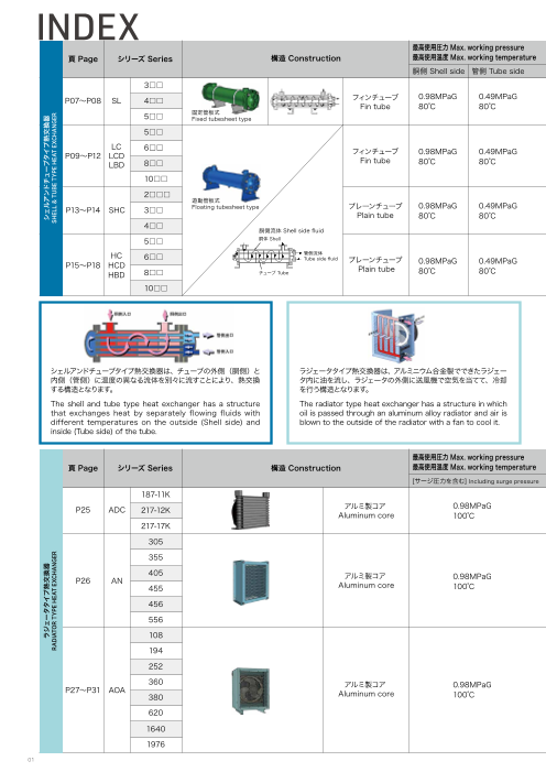
INDEX
最高使用圧力 Max. working pressure 胴側 Shell side
te (L/min) 伝熱面積 Heat Transfer Area (㎡)※
頁 Pag 構造 Construction 最高使用温度 Max. working temperature 油流量 Oil flow ra 交換熱量 Heat duty (kW)
e シリーズ Series
胴側 Shell side 管側 Tube side 0 200 400 600 800 1000 0 100 200 300 0 5 10 15 20 25 30 35
最高使用圧力 Max. working pressure 胴側 Shell side
3□□ 10~110 2.5~21 0.25~1.08 t Transfer Area (㎡)※
構造 Construction 最高使用温度 Max. working temperature 油流量 Oil flow rate (L/min) 交換熱量 Heat duty (kW) 伝熱面積 Hea
頁 Page シリーズ Series
P07~P08 SL 4□□ フィンチューブ 0.98MPaG 0.49MPaG
胴側 Shell side 管側 Tube side 0202~01060400 600 800 1000 05~32 100 200 300 0 0.73~25.03 10 15 20 25 30 35
Fin tube 80℃ 80℃
53□□ 固定管板式 1300~~131300 21.50~2612 0.215.7~81~.048.25
Fixed tubesheet type
P07~P08 SL 54□□ フィンチューブ 0.98MPaG 0.49MPaG 2400~126700 51~33~253 0.71.37~2~2.30.371
Fin tube 80℃ 80℃
LC 65□□ 固定管板式 3405~33505 106~6726 1.27.85~0~4.265.52
Fixed tubesheet type
P09~P12 LCD フィンチューブ 0.98MPaG 0.49MPaG
LBD 85□□ Fin tube 80℃ 80℃ 4800~~27605 13~3563~187 1.72~3.761.03~16.2
LC 160□□□□ 451~2305~5955 16~7660~275 2.50~6.52 11.1~25.9
P09~P12 LCD フィンチューブ 0.98MPaG 0.49MPaG
LBD 28□□□ Fin tube 80℃ 80℃ 5~804~5 605 1~736~187 0.08~0.23 6.03~16.2
遊動管板式
P13~P14 SHC 310□□□□ Floating tubesheet type プレーンチューブ 0.98MPaG 0.49MPaG 15~121015~955 4~23 60~275 0.26~0.90 11.1~25.9
Plain tube 80℃ 80℃
42□□□ 51~5~41530 17~~729 00.0.882~~01..2634
遊動管板式 胴側流体 Shell side fluid
P13~P14 SHC 53□□ Floating tubesheet type胴体 Shell プレーンチューブ 0.98MPaG 0.49MPaG 1355~121355 41~0~2342 00.2.863~~01.9.607
Plain tube 80℃ 80℃
HC 64□□ 管側流体 1450~~13105 71~42~956 0.812.6~1~1.624.40
胴側流体 Shell sidTueb fle usiidde fluid プレーンチューブ
P15~P18 HCD 0.98MPaG 0.49MPaG
HBD 85□□ チ胴ュ体ー Sブhe Tllube Plain tube 80℃ 80℃ 3855~~263450 10~3452~141 0.83~3.12.76~7 6.45
HC 160□□□□ 管側流体 401~003~15815 14~4556~247 1.61~2.40
Tube side fluid 6.98~14.0
プレーンチューブ
P15~P18 HCD 0.98MPaG 0.49MPaG
HBD 8□□ チューブ Tube Plain tube 80℃ 80℃ 85~640 35~141 3.27~6.45
10□□ 100~815 45~247 6.98~14.0
シェルアンドチューブタイプ熱交換器は、チューブの外側(胴側)と ラジェータタイプ熱交換器は、アルミニウム合金製でできたラジェー
内側(管側)に温度の異なる流体を別々に流すことにより、熱交換 タ内に油を流し、ラジェータの外側に送風機で空気を当てて、冷却
する構造となります。 を行う構造となります。
The shell and tube type heat exchanger has a structure The radiator type heat exchanger has a structure in which
that exchanges heat by separately flowing fluids with oil is passed through an aluminum alloy radiator and air is
different temperatures on the outside (Shell side) and blown to the outside of the radia最t高or使 w用it圧h力 a Mfaanx. twoo crkoiongl itp.inside (Tube side) of the tube. ressure
最高使用温度 Max. working temperature 油流量 Oil flow rate (L/min) 交換熱量 Heat duty (kW) 50Hz 伝熱面積 Heat Transfer Area (㎡) 空気側 Air side
頁 Page シリーズ Series 構造 Construction
[サージ圧力を含む] Including surge pressure 0 200 400 600 800 1000 0 10 20 30 40 50 60 70 80 0 10 20 30 40 50 60 70 80 90 100
最高使用圧力 Max. working pressure
頁 Page シリーズ1 8S7e-1r1ieK
1~10 0.4~0.9 0.5
s 最高使用温度 Max. working temperature 油流量 Oil flow rate (L/min) 交換熱量 Heat duty (kW) 50Hz 伝熱面積 Heat Transfer Area (㎡) 空気側 Air side
構造 Construction
P25 ADC 217-12K アルミ製コア 0.98MPaG
[サージ圧力を含む] Including surge pressure 01~12000 400 600 800 1000 00.5~110.0 20 30 40 50 60 70 80 00.6 10 20 30 40 50 60 70 80 90 100
Aluminum core 100℃
21187-171K 1~120 0.74~10.5.9 0..59
P25 ADC 21370-152K アルミ製コア 0.98MPaG 1~0~1070 02.5.4~~13.0.3 0.36.2
Aluminum core 100℃
21375-157K 1~0~12100 03.7.~0~1.5.2 0.94.4
4305 105~7100 25.4.~0~3.83.1 3.26.1
P26 AN アルミ製コア 0.98MPaG
4355 Aluminum core 100℃ 105~100 3.60.~3~5.120.1 4.47.7
45065 1250~110000 57.0.6~~81.12.2 6.110.0
P26 AN アルミ製コア 0.98MPaG
45565 Aluminum core 100℃ 1255~110500 6.31~0.180~.17.5 7.7 14.9
410586 1250~110000 57..6~91.21.2 7.510.0
519546 25~1500 91.02.~81~31.72.5 1144.5.9
210582 1355~~12000 5.6~139.13~20.4 7.5 18.1
319640 2450~120000 9.2~1613.5.2~25.5 14.5
アルミ製コア 26.1
P27~P31 AOA 0.98MPaG
328520 Aluminum core 100℃ 35~3200 131.37~.4~203.4.2 18.1 29.4
36260 アルミ製コア 405~2300 16.52~42.45~.549.4 26.1 47.0
P27~P31 AOA 0.98MPaG
1368400 Aluminum core 100℃ 3655~~34000 17.4~34.235.8~70.9 29.4 76.2
1692706 4750~340000 24.4~493.94.6~80.0 47.0 91.8
1640 65~400 35.8~70.9 76.2
1976 70~400 39.6~80.0 91.8
01
ラジェータタライジプェー熱タ交タ換イ器プ熱交換器 シェルアンドシチェュルーアブンタドイチプュ熱ーブ交タ換イ器プ熱交換器
RADIATOR TRYAPDEIA HTEOART T EYXPCEH HAENAGTE ERXCHANGER SHELL & TUSBHEE TLLY P&E T HUEBAET T EYXPCEH HAENAGTE ERXCHANGER
Page3
最高使用圧力 Max. working pressure 胴側 Shell side
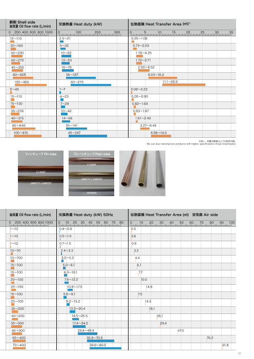
油流量 Oil flow rate (L/min) 交換熱量 Heat duty (kW) 伝熱面積 Heat Transfer Area (㎡)※
頁 Page シリーズ Series 構造 Construction 最高使用温度 Max. working temperature
胴側 Shell side 管側 Tube side 0 200 400 600 800 1000 0 100 200 300 0 5 10 15 20 25 30 35
最高使用圧力 Max. working pressure 胴側 Shell side
3□□ 油10流~量11 O0il flow rate (L/min) 交2.5換~熱21量 Heat duty (kW) 伝0.熱25面~1積.0 8Heat Transfer Area (㎡)※
頁 Page シリーズ Series 構造 Construction 最高使用温度 Max. working temperature
P07~P08 SL 4□□ フィンチューブ 0.98MPaG 0.49MPaG
胴側 Shell side 管側 Tube side 0202~01060400 600 800 1000 05~32 100 200 300 0 0.73~25.03 10 15 20 25 30 35
Fin tube 80℃ 80℃
53□□ 固定管板式 1300~~131300 21.50~2612 0.215.7~81~.048.25
Fixed tubesheet type
P07~P08 SL 54□□ フィンチューブ 0.98MPaG 0.49MPaG 2400~126700 51~33~253 0.71.37~2~2.30.371
Fin tube 80℃ 80℃
LC 65□□ 固定管板式 3405~33505 106~6726 1.27.85~0~4.265.52
Fixed tubesheet type
P09~P12 LCD フィンチューブ 0.98MPaG 0.49MPaG
LBD 85□□ Fin tube 80℃ 80℃ 4800~~27605 13~3563~187 1.72~3.761.03~16.2
LC 160□□□□ 451~2305~5955 16~7660~275 2.50~6.52 11.1~25.9
P09~P12 LCD フィンチューブ 0.98MPaG 0.49MPaG
LBD 28□□□ Fin tube 80℃ 80℃ 5~804~5 605 1~736~187 0.08~0.23 6.03~16.2
遊動管板式
P13~P14 SHC 310□□□□ Floating tubesheet type プレーンチューブ 0.98MPaG 0.49MPaG 15~121015~955 4~23 60~275 0.26~0.90 11.1~25.9
Plain tube 80℃ 80℃
42□□□ 51~5~41530 17~~729 00.0.882~~01..2634
遊動管板式 胴側流体 Shell side fluid
P13~P14 SHC 53□□ Floating tubesheet type胴体 Shell プレーンチューブ 0.98MPaG 0.49MPaG 1355~121355 41~0~2342 00.2.863~~01.9.607
Plain tube 80℃ 80℃
HC 64□□ 管側流体 1450~~13105 71~42~956 0.812.6~1~1.624.40
Tube side fluid プレーンチューブ
P15~P18 HCD 胴側流体 Shell side fluid 0.98MPaG 0.49MPaG
HBD 85□□ チ胴ュ体ー Sブhe Tllube Plain tube 80℃ 80℃ 3855~~263450 10~3452~141 0.83~3.12.76~7 6.45
HC 160□□□□ 管側流体 401~003~15815 14~4556~247 1.61~2.40
Tube side fluid 6.98~14.0
プレーンチューブ
P15~P18 HCD 0.98MPaG 0.49MPaG
Plain tube
HBD 8□□ チューブ Tube 80℃ 80℃ 85~640 35~141 3.27~6.45 ※但し、記載の数値以上でも制作可能。
We can also manufacture products with higher specifications those listed below.
10□□ 100~815 45~247 6.98~14.0
フィンチューブ Fin tube プレーンチューブ Plain tube
C1220T
C1220T
C6871T / C6872T
C6871T / C6872T
SUS304
最高使用圧力 Max. working pressure
最高使用温度 Max. working temperature 油流量 Oil flow rate (L/min) 交換熱量 Heat duty (kW) 50Hz 伝熱面積 Heat Transfer Area (㎡) 空気側 Air side
頁 Page シリーズ Series 構造 Construction
[サージ圧力を含む] Including surge pressure 0 200 400 600 800 1000 0 10 20 30 40 50 60 70 80 0 10 20 30 40 50 60 70 80 90 100
最高使用圧力 Max. working pressure
187-11K 1~10 0.4~0.9 0.5
最高使用温度 Max. working temperature 油流量 Oil flow rate (L/min) 交換熱量 Heat duty (kW) 50Hz 伝熱面積 Heat Transfer Area (㎡) 空気側 Air side
頁 Page シリーズ Series 構造 Construction
P25 ADC 217-12K アルミ製コア 0.98MPaG 01~12000 400 600 800 1000 00.5~110.0 20 30 40 50 60 70 80 00.6 10 20 30 40 50 60 70 80 90 100
Aluminum core [サージ圧力を含10む0] ℃Including surge pressure
21187-171K 1~120 0.74~10.5.9 0..59
P25 ADC 21370-152K アルミ製コア 0.98MPaG 1~0~1070 02.5.4~~13.0.3 0.36.2
Aluminum core 100℃
21375-157K 1~0~12100 03.7.~0~1.5.2 0.94.4
4305 105~7100 25.4.~0~3.83.1 3.26.1
P26 AN アルミ製コア 0.98MPaG
4355 Aluminum core 100℃ 105~100 3.60.~3~5.120.1 4.47.7
45065 1250~110000 57.0.6~~81.12.2 6.110.0
P26 AN アルミ製コア 0.98MPaG
45565 Aluminum core 100℃ 1255~110500 6.31~0.180~.17.5 7.7 14.9
410586 1250~110000 57..6~91.21.2 7.510.0
519546 25~1500 91.02.~81~31.72.5 1144.5.9
210582 1355~~12000 5.6~139.13~20.4 7.5 18.1
319640 2
アルミ製コア 450~120000 9.2~1613.5.2~25.5 14.5 26.1
P27~P31 AOA 0.98MPaG
328520 Aluminum core 100℃ 35~3200 131.37~.4~203.4.2 18.1 29.4
36260 405~2300 16.52~42.45~.5アルミ製コア 49.4 26.1
P27~P31 AOA 0.98MPaG 47.0
1368400 Aluminum core 100℃ 3655~~34000 17.4~34.235.8~70.9 29.4 76.2
1692706 4750~340000 24.4~493.94.6~80.0 47.0 91.8
1640 65~400 35.8~70.9 76.2
1976 70~400 39.6~80.0 91.8
02
ラジェータタライジプェー熱タ交タ換イ器プ熱交換器 シェルアンドシチェュルーアブンタドイチプュ熱ーブ交タ換イ器プ熱交換器
RADIATOR TRYAPDEIA HTEOART T EYXPCEH HAENAGTE ERXCHANGER SHELL & TUSBHEE TLLY P&E T HUEBAET T EYXPCEH HAENAGTE ERXCHANGER
Page4
SL LC/LCD/LBD SHC HC/HCD/HBD
SHELL & TUBE TYPE HEAT EXCHANGER
シェルアンドチューブタイプ熱交換器
タイプ別説明 Description by type
遊動管板式
胴体にボルト締めされた固定管板と熱応力に応じて動
くことのできる遊動管板をもつ構造です。管束は胴体
から抜き出すことができるので、胴側、管側とも清掃が
可能です。ただし、Oリングを使用しているため、高温
仕様には不向きです。
Floating Tubesheet Type
To allow for release of heat stress, the entire tube
bundle, features a slide-type construction. The pipe
assembly can be removed to facilitate cleaning.
固定管板式
管板が胴体に溶接されているため、胴側が高圧でも比
較的容易に対応が可能です。ただし、熱応力が大きい
場合は伸縮継手が必要です。管束は胴体から抜き出せ
ないため、胴側の清掃はできません。
Fixed Tubesheet Type
The cylindrical multi-tube type offers the simplest
construct ion. Heat stress is released during
expansion and contract ion of the body. The
temperature of the fluids both inside and outside are
relatively low, so in cases when it is not necessary to
deal with escaping heat, there is no need to attach
the expansion joint.
U字管式
U字形のチューブを使用したタイプです。チューブは片
方が拘束されていないため熱応力に対して自由です。管
束は胴体から抜き出すことができますが、U字のため
管側の清掃は困難です。
U-Tube Type
This design makes use of a U-shaped tube as the
heat conveyor. Because the heat conveyor tube is
able to expand and contract freely, unaffected by
the body, this design enables the tube assembly to
be easily extracted for inspection and cleaning.
遊動頭式
胴体にボルト締めされた固定管板と熱応力に応じて動く
ことのできる遊動頭をもつ構造です。仕様条件に対して
融通は利きますが、構造が複雑です。管束が胴体から
抜き出すことができるので、胴側、管側とも清掃が可
能です。
Floating Head Type
It has a fixed tube plate bolted to the fuselage
and a floating head that can move according to
thermal stress. Although flexibility is available
for specification requirements, the structure is
complicated. Since the tube bundle can be extracted
from the body, both the body side and the tube side
can be cleaned.
03
Page5
カムイは信頼できる規格に基づいた
製品づくりをしています。
Kamui products are based on dependable standards.
豊かな経験と確かな技術力に、TEMA、API、ASME等に基づく規格と In addition to a wealth of experience and precise engineering
世界中で高い評価をうけるH.T.R.I ( Heat Transfer Research.Inc. ) の capabilities, Kamui products are built in accordance to such world-
renowned international standards as TEMA, API, ASME, and others
信頼できる設計をプラス。ご要望に最も適した熱交換器を選定致します。 which have gained the approval of H.T.R.I (Heat Transfer Research.
遊動管板式から遊動頭式まで、4タイプの構造が可能です。 Inc.). As a customer's request, we are happy to make recommendations
for the most suitable type of heat exchanger model.Our four types
of products are possible, from “Floating Tubesheet Type” to “Floating
Head Type”.
胴側流体流路モデル Model of liquid flow on shell side
胴体 Shell
A F
A
B
B
B B
B B
A
E
胴体 Shell C
バッフル Baffle
[A] チューブとバッフル間の漏れ流れ [E] バッフルと胴体間の漏れ流れ
Leakage between tube and baffle Leakage between baffle and shell
[B] 管群を横切る流れ [F] 管群中央部(仕切板部分)のバイパス流れ
Cross-section view of pipe flow Bypass flow in center section (pass partition)
[C] 管群と胴体間のバイパス流れ
Bypass flow between tube and shell
バイパスフロー Bypass flow
H.T.R.I. 法による胴側流体の流れ。5つの流路に分け、各流路
の圧力バランスにより有効流量・圧力損失・伝熱係数等を算出
する。
Flow of fuselage fluid by H. T. R. I. method. Divided into five
flow paths, and by the pressure balance of each flow path
Calculate effective flow rate, pressure loss, heat transfer
coefficient, etc. シーリングディバイス
Sealing device
バイパス流れ
Bypass flow
○第一種圧力容器製造認定工場でつくり出される製品は常に厳しくチェックされます。
○ASMEに準拠した溶接をはじめとする、各工程における一貫した管理システムの中で優れた製品が生まれます。
○製品に付けられる品質保証はカムイの自信です。
○1997年 12月 ISO9001 認証取得
○2012年 9月 ISO14001 認証取得
● Products are manufactured in plants certified for class-1 pressure vessel, and undergo rigid checks at all phases of production.
●Welding is based on ASME standards. Comprehensive inspections and control at each stage ensure products of the highest quality.
● The product warranty reflects KAMUI's complete confidence in its products.
● Dec. 1997 ISO9001 certification obtained.
● Sep. 2012 ISO14001 certification obtained.
04
SL LC LCD / LBD SHC HC HCD / HBD ADC / AN AOA-A AOA-A-S AOA-A-DE
Page6
分解図 Exploded view
遊動管板式 構造・材質 Floating Tubesheet Type Structure / Material
管束 Tube bundle
※胴体の直径が6B(φ165.2)以下の場合、 22 ライナは付きません。 21 Oリングは1本です。
Product with shell diameter is 6B ( Φ 165.2) or less: 22 No liner. 21 One O-ring.
標準材質 Standard material
材質 材質
No. 部品名 Material No. 部品名 Material
Part name 清水用 /海水用 Part name 清水用 /海水用
For fresh water/For sea water For fresh water/For sea water
1 胴体
Shell SGP 12 ドレンソケット
Drain socket SS400
2 ボンネット (S) FC200 13 ドレンプラグ
Drain plug SS400
Bonnet
3 (F) FC200 14 プラグ
防食 Corro. Plug SS400/C3604B
亜鉛棒 Eliminator
4 フランジ
Flange SS400 15 with plug 防食材
Corro.Eliminator ZnB
5 管板
Tubesheet SS400 / C4621P 16 温度計ソケット
Thermometer socket SS400
6 チューブ C1220T/C6871TTube C6872T 17 温度計プラグ
Thermometer plug SS400
7 管束 タイロッド
Tube bundle Tie rod SS400 18 ボルト・ナット
Bolt & Nut SWRM
8 バッフル
Baffle SS400 19 ガスケット (A) NON-ASB
スペーサ Gasket
9 Spacer STKM 20 (B) NON-ASB
10 胴側ノズルフランジ
Shell side nozzle flange SS400 21 Oリング
O-Ring NBR
11 サドル
Saddle SS400 22 ライナ
Liner SS400
05
Page7
標準型式の説明 Description of Standard Model
SL series
型式表示例 1
Model display example SL - 2 305 3 W 4 1 5 (-R)
1 シリーズ Series 4 胴側流量区分 Oil flow rate category
1 : 1 型 [ Type 1 ]
2 モデルナンバー Model number 2 : 2 型 [ Type 2 ]
5 バイパスバルブの有無 Bypass valve
3 管側パス数 Number of passes 無記入 - Blank - : 無 ( 標準 ) [ No valve (Standard) ]
W :4 パス [ 4 Pass ] -R : 有 [ With valve ]
U :2 パス [ 2 Pass ]
LC / LCD / LBD series
型式表示例 0 1 2 3 4
Model display example (F -) LC - 870 F 2
0 オプション Option 1 シリーズ Series
A-:サーボ用 (ガスケットA:PTFE フラッシング) LC/LCD/LBD : フィンチューブ [ Fin tube ]
[ for servo (Gasket-A:PTFE Flushing) ] 末尾にAが入っている場合は、標準外になります。
L -:水グリ用 [ for water-glycol group hydraulic fluid ] If "A" is in the end, it is special specification.
F -:Oリング(FPM) [ O-ring material “FPM” ]
2 モデルナンバー 3 胴側取合形状 Oil port connection type 4 胴側流量区分 Oil flow rate category
Model number F:フランジ [ Flange ] 1:1型 [ Type1 ] 2:2型 [ Type2 ] 3:3型 [ Type3 ]
P:ねじ込み [ Screw ]
SHC series
型式表示例 0 1 2 3 4
Model display example (F -) SHC - 310 F 1
0 オプション Option 1 シリーズ Series
A-:サーボ用 (ガスケットA:PTFE フラッシング) SHC : プレーンチューブ [ Plain tube ]
[ for servo (Gasket-A:PTFE Flushing) ] 末尾にAが入っている場合は、標準外になります。
L-:水グリ用 [ for water-glycol group hydraulic fluid ] If "A" is in the end, it is special specification.
F-:Oリング(FPM) [ O-ring material “FPM” ]
2 モデルナンバー 3 胴側取合形状 Oil port connection type 4 胴側流量区分 Oil flow rate category
Model number F:フランジ [ Flange ] 1:1型 [ Type1 ] 2:2型 [ Type2 ] 3:3型 [ Type3 ]
P:ねじ込み [ Screw ]
HC / HCD / HBD series
型式表示例 0 1 2 3 4
Model display example (F -) HC - 870 F 2
0 オプション Option 1 シリーズ Series
A-:サーボ用 (ガスケットA:PTFE フラッシング) HC/HCD/HBD : プレーンチューブ [ Plain tube ]
[ for servo (Gasket-A:PTFE Flushing) ] 末尾にAが入っている場合は、標準外になります。
L-:水グリ用 [ for water-glycol group hydraulic fluid ] If "A" is in the end, it is special specification.
F-:Oリング(FPM) [ O-ring material “FPM” ]
2 モデルナンバー 3 胴側取合形状 Oil port connection type 4 胴側流量区分 Oil flow rate category
Model number F:フランジ [ Flange ] 1:1型 [ Type1 ] 2:2型 [ Type2 ] 3:3型 [ Type3 ]
P:ねじ込み [ Screw ]
06
SL LC LCD / LBD SHC HC HCD / HBD ADC / AN AOA-A AOA-A-S AOA-A-DE
Page8
SL 3-5B / FIN TUBE TYPE
series 清水用 For fresh water
特許取得済:日本・米国・台湾
型式表示例 1 2 3 4 5
Model display example SL - 305 W 1 (-R)
1 シリーズ Series 2 モデルナンバー Model number 3 管側パス数 Number of passes
W :4 パス [ 4 Pass ]
U :2 パス [ 2 Pass ]
4 胴側流量区分 Oil flow rate category 5 バイパスバルブの有無 Bypass valve
1 : 1 型 [ Type 1 ] 無記入 - Blank - : 無 ( 標準 ) [ No valve (Standard) ]
2 : 2 型 [ Type 2 ] -R : 有 [ With valve ]
I N A OUT
D G
2-Rc(Q)
2-Rc(P )
OUT L
φN C φM
I N
H
MAX. (E) 2×2-K J
最高使用圧力 胴側:0.98MPaG / 管側:0.49MPaG 最高使用温度 胴側:80℃ /管側:80℃
Max. working pressure Shell side : 0.98MPaG / Tube side : 0.49MPaG Max. working temperature Shell side: 80℃ / Tube side: 80℃
標準塗装色 暗緑色
Standard paint color Dark green
1 2 A C D E G H J K L M N P Q 質量 Mass 伝熱面積 Area
(kg) (m2)
SL-303 295 152 87 7 0.25
304 367 224 159 7.5 0.36
305 439 45 296 231 74 87 58 11×20 62 120 89.1 3/4 3/4 8.5 0.46
307 583 440 375 10 0.67
309 727 584 519 12 0.87
311 871 728 663 14 1.08
SL-408 449 284 214 14.5 0.73
411 593 428 358 17 1.05
415 737 60 572 502 85 125 110 18×22 87 150 114.3 11/4 3/4 19.5 1.38
418 881 716 646 22.5 1.70
421 1025 860 790 24.5 2.03
SL-518 628 406 321 27 1.78
526 844 70 622 537 116 160 120 18×25 105 180 139.8 11/2 1 33 2.60
534 1060 838 753 40 3.43
542 1276 1054 969 44 4.25
単位 Unit:mm
5 ■ 管束内にバイパス回路(型式最後尾に “-R” 付)を設けたタイプも製作致します。
■ Internal bypass device (remarked “-R”at the end) is available as an option.
バイパス構造 Bypass structure SL-5B についてはバイパス構造はありません。
No bypass structure inside SL-5B.
07
Page9
性能グラフ PERFORMANCE
条件 Condition
流体:ISO VG32 相当 / 油入口温度:65℃ / 水入口温度:30℃
Fluid: ISO VG32 equivalent. / Oil inlet temperature : 65℃ / Water inlet temperature : 30℃
上記と異なる条件でご使用の場合はP33の「選定仕様書」を正確に記入の上、弊社までご連絡下さい。
Please contact us online for your inquiries by filling out the specifications form in page34.
SL-3 series 冷却水量 Water flow rate: 20L/min SL-4 series 冷却水量 Water flow rate: 30L/min
40
25
35
5
8 4
20 30
3
7
6
25
15
5 4 2
20
3 1
2
10 15
1
4
1 303W1 4
10
2 304W1 1 408W1
5 3 305W1 2 411W1
4 305W2 3 415W2
5 307W1 4 418W2
6 307W2 5 5 421W2
7 309W2
8 311W2
0 0
0 50 100 150 200 0 50 100 150 200 250
油流量 Oil flow rate:Ws(L/min) 油流量 Oil flow rate:Ws(L/min)
SL-5 series 冷却水量 Water flow rate: 50L/min 3
※ 性能グラフは “W” タイプとなります。
70 ※ “U” タイプの冷却水量は “W” タイプの倍必要になります。
※ The performance curve shows “W” type.
6 ※ Water flow rate of “U” type is twice as much as “W” type.
60
5
3
50 4
2 管板 Tube sheet 管板 Tube Sheet
Oリング O-Ring 胴体 Shell チューブ Tube バッフル Baffle 芯金 Core bar Oリング O-Ring
40 ボンネット Bonnet ボンネット Bonnet
1
30
ドレン Drain socket
20
4 サドル Saddle ドレンプラグ Drain plug
1 518W1
2 526W1
10 3 526W2
4 534W1
5 534W2
6 542W2
0
0 100 200 300 400 500
油流量 Oil flow rate:Ws(L/min)
※本カタログ掲載の仕様及び外観等は、改良のため予告なく変更される場合があります。
The specifications in this catalog, including the products appearance, may change without prior notice. 08
交換熱量 Heat duty:Q(kW) 交換熱量 Heat duty:Q(kW)
交換熱量 Heat duty:Q(kW)
SL LC LCD / LBD SHC HC HCD / HBD ADC / AN AOA-A AOA-A-S AOA-A-DE
Page10
LC 5-10B / FIN TUBE TYPE
series 清水用 For fresh water
型式表示例 1
example LC - 2 870 3M l d s l y F 4ode i p a 2
1 シリーズ Series 2 モデルナンバー Model number 3 胴側取合形状 Oil port connection type
LC : フィンチューブ [ Fin tube ] P:ねじ込み [ Screw ] F:フランジ [ Flange ]
清水用 [ For fresh water ]
末尾にAが入っている場合は、標準外になります。 4 胴側流量区分 Oil flow rate category
If "A" is in the end, it is special specification. 1:1型 [ Type1 ] 2:2型 [ Type2 ] 3:3型 [ Type3 ]
3 P type I N A OUT
D G
2-Rc(P) 2-Rc(Q)
OUT> L
φN C φM
I N
H
B
E 2×2-K J
3 F type I N A OUT
>
D > G >
2-(P)B JIS10K FF
2-Rc(Q)
OUT F
φN C φM
I N
H
E B
2×2-K J
最高使用圧力 胴側:0.98MPaG / 管側:0.49MPaG 最高使用温度 胴側:80℃ /管側:80℃
Max. working pressure Shell side : 0.98MPaG / Tube side : 0.49MPaG Max. working temperature Shell side: 80℃ / Tube side: 80℃
標準塗装色 メタリックブルー
Standard paint color Metallic blue
1 2 A B C D E F G H J K L M N P Q 質量 Mass 伝熱面積 Area
(kg) (m2)
LC-515 715 430 584 41 1.72
520 845 560 714 45 2.23
525 985 77 65 700 854 140 160 160 120 18×25 125 195 139.8 11/2 3/4 49 2.78
530 1105 820 974 52 3.24
535 1225 940 1094 56 3.71
LC-625 740 400 594 58 2.50
630 870 530 724 63 3.24
640 1010 670 864 69 4.03
645 1130 97 70 790 984 160 185 180 140 18×30 135 230 165.2 2 1 74 4.71
650 1250 910 1104 79 5.38
660 1360 1020 1214 83 6.01
665 1450 1110 1304 87 6.52
LC-860 885 520 708 108 6.03
870 1025 660 848 118 7.50
885 1145 780 968 126 8.77
8100 1265 900 1088 135 10.0
8110 1375 94 100 1010 1198 180 195 200 160 22×35 175 280 216.3 21/2 11/4 143 11.1
8120 1465 1100 1288 149 12.1
8135 1615 1250 1438 160 13.7
8145 1685 1320 1508 165 14.4
8160 1855 1490 1678 177 16.2
LC-10110 1040 640 848 170 11.1
10130 1160 760 968 182 12.9
10145 1280 880 1088 194 14.8
10165 1390 990 1198 205 16.5
10180 1480 104 120 1080 1288 220 215 250 200 22×35 ※ 340 267.4 3 11/2 214 17.9
10200 1630 1230 1438 230 20.3
10210 1700 1300 1508 237 21.4
10240 1870 1470 1678 254 24.0
10260 1990 1590 1798 266 25.9
※ LC-10 シリーズは胴側取合フランジタイプのみ。 単位 Unit:mm
Shell side connection of LC-10 series is flange type only.
09
>
>
>
> >
>
>
>
>
> >
>
>
>
Page11
性能グラフ PERFORMANCE
条件 Condition
流体:ISO VG32 相当 / 油入口温度:65℃ / 水入口温度:30℃
Fluid: ISO VG32 equivalent. / Oil inlet temperature : 65℃ / Water inlet temperature : 30℃
上記と異なる条件でご使用の場合はP33の「選定仕様書」を正確に記入の上、弊社までご連絡下さい。
Please contact us online for your inquiries by filling out the specifications form in page34.
LC-5 series 冷却水量 Water flow rate: 50L/min LC-6 series 冷却水量 Water flow rate: 60L/min
55 80
535 665
50 660
70
530 650
45
645
525 60
40 640
520
35 50
630
515
30 40 625
25
30
20
4 20 4
15 1型 Type1:40~145L/min 1型 Type1:45~175L/min
2型 Type2:55~205L/min 2型 Type2:70~265L/min
3型 Type3:70~270L/min 3型 Type3:90~355L/min
10 10
30 70 110 150 190 230 270 310 25 75 125 175 225 275 325 375
油流量 Oil flow rate:Ws(L/min) 油流量 Oil flow rate:Ws(L/min)
LC-8 series 冷却水量 Water flow rate: 150L/min LC-10 series 冷却水量 Water flow rate: 200L/min
290
190 8160 10260
8145 270 10240
170 8135
250 10210
8120 10200
8110 230 10180
150
8100 10165
210
885 10145
130
190
870 10130
110 170 10110
860
150
90
130
70 110
4 90 4
50
1型 Type1: 80 ~ 315L/min 1型 Type1:120 ~ 460L/min
2型 Type2:120 ~ 460L/min 70 2型 Type2:180 ~ 710L/min
3型 Type3:155 ~ 605L/min 3型 Type3:240 ~ 955L/min
30 50
50 150 250 350 450 550 650 100 200 300 400 500 600 700 800 900 1000 1100
油流量 Oil flow rate:Ws(L/min) 油流量 Oil flow rate:Ws(L/min)
※本カタログ掲載の仕様及び外観等は、改良のため予告なく変更される場合があります。
The specifications in this catalog, including the products appearance, may change without prior notice. 10
交換熱量 Heat duty:Q(kW) 交換熱量 Heat duty:Q(kW)
交換熱量 Heat duty:Q(kW) 交換熱量 Heat duty:Q(kW)
SL LC LCD / LBD SHC HC HCD / HBD ADC / AN AOA-A AOA-A-S AOA-A-DE
Page12
LCD 5-10B / FIN TUBE TYPE
series 清水用 For fresh water
型式表示例 1
odel disp ay example LCD - 2 870 3M F 4l 2
1 シリーズ Series 2 モデルナンバー Model number 3 胴側取合形状
LCD : フィンチューブ [ Fin tube ] Oil port connection type
清水用 [ For fresh water ] F:フランジ [ Flan
管側取合形状フランジ [ Water port connection flange type ] 4 胴側流量区分 Oil flow rate category ge ]
末尾にAが入っている場合は、標準外になります。 1:1型 [ Type1 ]
If "A" is in the end, it is special specification. 2:2型 [ Type2 ]
3:3型 [ Type3 ]
I N A OUT
D G 2(- Q)B JIS10K FF
2- (P)B JIS10K FF
OUT
F
φM φN C
I N
H
B
E 2×2-K J
最高使用圧力 胴側:0.98MPaG / 管側:0.49MPaG 最高使用温度 胴側:80℃ /管側:80℃
Max. working pressure Shell side : 0.98MPaG / Tube side : 0.49MPaG Max. working temperature Shell side: 80℃ / Tube side: 80℃
標準塗装色 メタリックブルー
Standard paint color Metallic blue
1 2 A B C D E F G H J K M N P Q 質量 Mass 伝熱面積 Area
(kg) (m2)
LCD-515 765 430 584 51 1.72
520 895 560 714 55 2.23
525 1035 77 150 700 854 140 210 160 120 18×25 195 139.8 11/2 11/4 59 2.78
530 1155 820 974 62 3.24
535 1275 940 1094 66 3.71
LCD-625 800 400 594 70 2.50
630 930 530 724 75 3.24
640 1070 670 864 81 4.03
645 1190 97 160 790 984 160 245 180 140 18×30 230 165.2 2 11/2 86 4.71
650 1310 910 1104 91 5.38
660 1420 1020 1214 95 6.01
665 1510 1110 1304 99 6.52
LCD-860 955 520 708 123 6.03
870 1095 660 848 133 7.50
885 1215 780 968 141 8.77
8100 1335 900 1088 150 10.0
8110 1445 94 200 1010 1198 180 265 200 160 22×35 280 216.3 21/2 2 158 11.1
8120 1535 1100 1288 164 12.1
8135 1685 1250 1438 175 13.7
8145 1755 1320 1508 180 14.4
8160 1925 1490 1678 192 16.2
LCD-10110 1120 640 848 189 11.1
10130 1240 760 968 201 12.9
10145 1360 880 1088 213 14.8
10165 1470 990 1198 224 16.5
10180 1560 104 220 1080 1288 220 295 250 200 22×35 340 267.4 3 21/2 233 17.9
10200 1710 1230 1438 249 20.3
10210 1780 1300 1508 256 21.4
10240 1950 1470 1678 273 24.0
10260 2070 1590 1798 285 25.9
※性能グラフは LCシリーズと同様。 単位 Unit:mm
The performance curve is the same as LC series.
※本カタログ掲載の仕様及び外観等は、改良のため予告なく変更される場合があります。
11 The specifications in this catalog, including the products appearance, may change without prior notice.
>
Page13
LBD 5-10B / FIN TUBE TYPE
series 海水用 For sea water
型式表示例 1
example LBD - 2 870 3o e i p a F 4M d l d s l y 2
1 シリーズ Series 2 モデルナンバー Model number 3 胴側取合形状
LBD : フィンチューブ [ Fin tube ] Oil port connection type
海水用 [For sea water ]
管側取合形状フランジ [ Water port connection flange type ] 4 胴側流量区分 Oil flow rate category F:フランジ [ Flange ]
1:1型 [ Type1 ]
末尾にAが入っている場合は、標準外になります。 2:2型 [ Type2 ]
If "A" is in the end, it is special specification. 3:3型 [ Type3 ]
I N A OUT
D G 2(- Q)B JIS10K FF
2- (P)B JIS10K FF
OUT
F
φM φN C
I N
H
B
E 2×2-K J
最高使用圧力 胴側:0.98MPaG / 管側:0.49MPaG 最高使用温度 胴側:80℃ /管側:80℃
Max. working pressure Shell side : 0.98MPaG / Tube side : 0.49MPaG Max. working temperature Shell side: 80℃ / Tube side: 80℃
標準塗装色 メタリックブルー
Standard paint color Metallic blue
1 2 A B C D E F G H J K M N P Q 質量 Mass 伝熱面積 Area
(kg) (m2)
LBD-515 800 430 584 53 1.72
520 930 560 714 57 2.23
525 1070 77 150 700 854 140 210 160 120 18×25 195 139.8 11/2 11/4 61 2.78
530 1190 820 974 64 3.24
535 1310 940 1094 68 3.71
LBD-625 830 400 594 72 2.50
630 960 530 724 77 3.24
640 1100 670 864 83 4.03
645 1220 97 160 790 984 160 245 180 140 18×30 230 165.2 2 11/2 88 4.71
650 1340 910 1104 93 5.38
660 1450 1020 1214 97 6.01
665 1540 1110 1304 101 6.52
LBD-860 1000 520 708 130 6.03
870 1140 660 848 140 7.50
885 1260 780 968 148 8.77
8100 1380 900 1088 157 10.0
8110 1490 94 200 1010 1198 180 265 200 160 22×35 280 216.3 21/2 2 165 11.1
8120 1580 1100 1288 171 12.1
8135 1730 1250 1438 182 13.7
8145 1800 1320 1508 187 14.4
8160 1970 1490 1678 199 16.2
LBD-10110 1170 640 848 201 11.1
10130 1290 760 968 213 12.9
10145 1410 880 1088 225 14.8
10165 1520 990 1198 236 16.5
10180 1610 104 220 1080 1288 220 295 250 200 22×35 340 267.4 3 21/2 245 17.9
10200 1760 1230 1438 261 20.3
10210 1830 1300 1508 268 21.4
10240 2000 1470 1678 285 24.0
10260 2120 1590 1798 297 25.9
※性能グラフは LCシリーズと同様。 単位 Unit:mm
The performance curve is the same as LC series.
※本カタログ掲載の仕様及び外観等は、改良のため予告なく変更される場合があります。
The specifications in this catalog, including the products appearance, may change without prior notice. 12
SL LC LCD / LBD SHC HC HCD / HBD ADC / AN AOA-A AOA-A-S AOA-A-DE
>
Page14
SHC 2-4B / PLAIN TUBE TYPE
series 清水用 For fresh water
型式表示例 1 SHC - 2 310 3 F 4Model display example 1
1 シリーズ Series 2 モデルナンバー 3 胴側取合形状 4 胴側流量区分 Oil flow rate category
SHC : プレーンチューブ [ Plain tube ] Model number Oil port connection type 1:1型 [ Type1 ]
清水用 [ For fresh water ] P:ねじ込み [ Screw ] 2:2型 [ Type2 ]
末尾にAが入っている場合は、標準外になります。 F:フランジ [ Flange ] 3:3型 [ Type3 ]
If "A" is in the end, it is special specification.
3 P type I N A OUT
>
D > G >
2-Rc(P) 2-Rc(Q)
OUT> L
φN C φM
I N
H
B
E > 2×2-K
> J >
3 F type I N A OUT
D G
2-(P)B JIS10K FF
2-Rc(Q)
OUT F
φN C φM
I N
H
E B> 2×2-K
> J
最高使用圧力 胴側:0.98MPaG / 管側:0.49MPaG 最高使用温度 胴側:80℃ /管側:80℃
Max. working pressure Shell side : 0.98MPaG / Tube side : 0.49MPaG Max. working temperature Shell side: 80℃ / Tube side: 80℃
標準塗装色 メタリックブルー
Standard paint color Metallic blue
1 2 A B C D E F G H J K L M N P Q 質量 Mass 伝熱面積 Area
(kg) (m2)
SHC-2010 286 144 273 6 0.08
2015 396 68 32 254 383 80 76 70 50 11×15 50 100 60.5 1/2 1/2 7 0.13
2020 506 364 493 8 0.18
2025 616 474 603 9 0.23
SHC-303 374 192 341 11 0.26
304 464 282 431 12 0.35
305 554 372 521 13 0.44
306 644 78 45※ 462 611 93 97 87 58 11×20 63 128 89.1 3/4 3/4 14.5 0.53
307 734 552 701 16 0.62
308 824 642 791 17 0.71
309 914 732 881 18 0.81
310 1004 822 971 19 0.90
SHC-410 699 465 599 28 0.82
412 814 580 714 30 0.98
414 929 67 60 695 829 125 129 125 110 18×22 115 170 114.3 1 3/4 32 1.15
416 1044 810 944 35 1.32
418 1159 925 1059 37 1.49
420 1264 1030 1164 39 1.64
単位 Unit:mm
※2022年1月製作分より40mm→45mmに変更になっています。
The size has been changed from 40mm to 45mm from the January 2022 production.
13
> >
> >
>
>
>
> >
>
>
> >
>
>
> >
>
> > >
>
>
>
>
>
> >
Page15
性能グラフ PERFORMANCE
条件 Condition
流体:ISO VG32 相当 / 油入口温度:65℃ / 水入口温度:30℃
Fluid: ISO VG32 equivalent. / Oil inlet temperature : 65℃ / Water inlet temperature : 30℃
上記と異なる条件でご使用の場合はP33の「選定仕様書」を正確に記入の上、弊社までご連絡下さい。
Please contact us online for your inquiries by filling out the specifications form in page34.
SHC-2 series 冷却水量 Water flow rate: 10L/min SHC-3 series 冷却水量 Water flow rate: 20L/min
8
24
310
7 2025 22
309
20
6 308
2020
18 307
5
16 306
2015
14
4 305
12
304
3 2010
10
303
2 8
4 6
1 4
1型 Type1: 5 ~ 18L/min 1型 Type1:15 ~ 45L/min
2型 Type2:10 ~ 30L/min 4 2型 Type2:25 ~ 80L/min
3型 Type3:15 ~ 45L/min 3型 Type3:30 ~ 115L/min
0 2
0 10 2 0 30 40 50 60 10 30 50 70 90 110 130
油流量 Oil flow rate:Ws(L/min) 油流量 Oil flow rate:Ws(L/min)
SHC-4 series 冷却水量 Water flow rate: 40L/min
32
30
420
28 418
26
416
24
414
22
20 412
18
410
16
14
12
10 4
1型 Type1:15 ~ 55L/min
8 2型 Type2:25 ~ 95L/min
3型 Type3:35 ~ 130L/min
6
10 30 50 70 90 110 130 150
油流量 Oil flow rate:Ws(L/min)
※本カタログ掲載の仕様及び外観等は、改良のため予告なく変更される場合があります。
The specifications in this catalog, including the products appearance, may change without prior notice. 14
交換熱量 Heat duty:Q(kW) 交換熱量 Heat duty:Q(kW)
交換熱量 Heat duty:Q(kW)
SL LC LCD / LBD SHC HC HCD / HBD ADC / AN AOA-A AOA-A-S AOA-A-DE
Page16
HC 5-10B / PLAIN TUBE TYPE
series 清水用 For fresh water
型式表示例 1 2 3 4
Model display example HC - 870 F 2
1 シリーズ Series 2 モデルナンバー 3 胴側取合形状 4 胴側流量区分 Oil flow rate category
HC : プレーンチューブ [ Plain tube ] Model number Oil port connection type 1:1型 [ Type1 ]
清水用 [ For fresh water ] P:ねじ込み [ Screw ] 2:2型 [ Type2 ]
末尾にAが入っている場合は、標準外になります。 F:フランジ [ Flange ] 3:3型 [ Type3 ]
If "A" is in the end, it is special specification.
3 P type
IN A OUT
D G
2-Rc(P) 2-Rc(Q)
OUT> L
φN C φM
IN
H
B
E 2×2-K J
3 F type IN A OUT
D G
2-(P)B JIS10K FF
2-Rc(Q)
OUT F
φN C φM
IN
H
E B 2×2-K J
最高使用圧力 胴側:0.98MPaG / 管側:0.49MPaG 最高使用温度 胴側:80℃ /管側:80℃
Max. working pressure Shell side : 0.98MPaG / Tube side : 0.49MPaG Max. working temperature Shell side: 80℃ / Tube side: 80℃
標準塗装色 メタリックブルー
Standard paint color Metallic blue
1 2 A B C D E F G H J K L M N P Q 質量 Mass 伝熱面積 Area
(kg) (m2)
HC-510 739 460 616 38 0.83
512 849 570 726 41 0.99
514 964 78 65 685 841 140 153 160 120 18×25 120 195 139.8 11/4 3/4 44 1.15
516 1084 805 961 47 1.33
518 1194 915 1071 50 1.49
520 1319 1040 1196 53 1.67
HC-620 922 82 620 784 162 59 1.61
623 1032 735 894 63 1.85
625 1102 79.5 70 805 964 150 159.5 180 140 18×30 140 230 165.2 11/2 1 65 2.00
627 1177 880 1039 68 2.17
630 1282 985 1144 72 2.40
HC-840 1065 720 888 120 3.27
850 1265 920 1088 130 4.03
860 1465 84 100 1120 1288 180 185 200 160 22×35 160 280 216.3 2 11/4 140 4.80
870 1685 1340 1508 155 5.64
880 1895 1550 1718 170 6.45
HC-1080 1160 780 968 180 6.98
1090 1280 900 1088 195 7.88
10100 1390 94 120 1010 1198 220 205 250 200 22×35 200 340 267.4 21/2 11/2 205 8.70
10120 1630 1250 1438 230 10.4
10140 1870 1490 1678 255 12.2
10160 2110 1730 1918 280 14.0
単位 Unit:mm
15
>
>
>
>
>
>
>
>
Page17
性能グラフ PERFORMANCE
条件 Condition
流体:ISO VG32 相当 / 油入口温度:65℃ / 水入口温度:30℃
Fluid: ISO VG32 equivalent. / Oil inlet temperature : 65℃ / Water inlet temperature : 30℃
上記と異なる条件でご使用の場合はP33の「選定仕様書」を正確に記入の上、弊社までご連絡下さい。
Please contact us online for your inquiries by filling out the specifications form in page34.
HC-5 series 冷却水量 Water flow rate: 50L/min HC-6 series 冷却水量 Water flow rate: 80L/min
45 65
520
60
40 518
630
55
516
35 627
50
514 625
623
30 45
512
620
40
25 510
35
20
30
15 25
20
4
10 4
1型 Type1:35 ~ 125L/min 1型 Type1:40 ~ 155L/min
2型 Type2:50 ~ 180L/min 15 2型 Type2:60 ~ 235L/min
3型 Type3:60 ~ 235L/min 3型 Type3:80 ~ 315L/min
5 10
25 75 125 175 225 275 0 50 100 150 200 250 300 350
油流量 Oil flow rate:Ws(L/min) 油流量 Oil flow rate:Ws(L/min)
HC-8 series 冷却水量 Water flow rate: 150L/min HC-10 series 冷却水量 Water flow rate: 250L/min
150
880 265
140
10160
130 870 240
10140
120
860 215
10120
110
850 190
100 10100
1090
165
90 1080
840
80 140
70
115
60
90
50
4 4
1型 Type1: 85 ~ 335L/min 65 1型 Type1:100 ~ 390L/min
40 2型 Type2:125 ~ 485L/min 2型 Type2:155 ~ 605L/min
3型 Type3:165 ~ 640L/min 3型 Type3:205 ~ 815L/min
30 40
50 150 250 350 450 550 650 750 50 150 250 350 450 550 650 750 850 950
油流量 Oil flow rate:Ws(L/min) 油流量 Oil flow rate:Ws(L/min)
※本カタログ掲載の仕様及び外観等は、改良のため予告なく変更される場合があります。
The specifications in this catalog, including the products appearance, may change without prior notice. 16
交換熱量 Heat duty:Q(kW) 交換熱量 Heat duty:Q(kW)
交換熱量 Heat duty:Q(kW) 交換熱量 Heat duty:Q(kW)
SL LC LCD / LBD SHC HC HCD / HBD ADC / AN AOA-A AOA-A-S AOA-A-DE
Page18
HCD 5-10B / PLAIN TUBE TYPE
series 清水用 For fresh water
型式表示例 1 2 3 4
Model display example HCD - 870 F 2
1 シリーズ Series 2 モデルナンバー Model number 3 胴側取合形状
HCD : プレーンチューブ [ Plain tube ] Oil port connection type
清水用 [ For fresh water ]
管側取合形状フランジ [ Water port connection flange type ] 4 胴側流量区分 Oil flow rate category F:フランジ [ Flange ]
末尾にAが入っている場合は、標準外になります。 1:1型 [ Type1 ]
If "A" is in the end, it is special specification. 2:2型 [ Type2 ]
3:3型 [ Type3 ]
IN A OUT
D G 2-(Q)B JIS10K FF
2-(P)B JIS10K FF
OUT
F
φM φN C
IN
H
B
E 2×2-K J
最高使用圧力 胴側:0.98MPaG / 管側:0.49MPaG 最高使用温度 胴側:80℃ /管側:80℃
Max. working pressure Shell side : 0.98MPaG / Tube side : 0.49MPaG Max. working temperature Shell side: 80℃ / Tube side: 80℃
標準塗装色 メタリックブルー
Standard paint color Metallic blue
1 2 A B C D E F G H J K M N P Q 質量 Mass 伝熱面積 Area
(kg) (m2)
HCD-510 789 460 616 48 0.83
512 899 570 726 51 0.99
514 1014 78 150 685 841 140 203 160 120 18×25 195 139.8 11/4 11/4 54 1.15
516 1134 805 961 57 1.33
518 1244 915 1071 60 1.49
520 1369 1040 1196 63 1.67
HCD-620 982 82 620 784 222 71 1.61
623 1092 735 894 75 1.85
625 1162 160
79.5 805 964 150
219.5 180 140 18×30 230 165.2 11/2 11/2 77 2.00
627 1237 880 1039 80 2.17
630 1342 985 1144 84 2.40
HCD-840 1135 720 888 135 3.27
850 1335 920 1088 145 4.03
860 1535 84 200 1120 1288 180 255 200 160 22×35 280 216.3 2 2 155 4.80
870 1755 1340 1508 170 5.64
880 1965 1550 1718 185 6.45
HCD-1080 1240 780 968 199 6.98
1090 1360 900 1088 214 7.88
10100 1470 94 220 1010 1198 220 285 250 200 22×35 340 267.4 21/2 21/2 224 8.70
10120 1710 1250 1438 249 10.4
10140 1950 1490 1678 274 12.2
10160 2190 1730 1918 299 14.0
単位 Unit:mm
※性能グラフはHCシリーズと同様。
The performance curve is the same as HC series.
※本カタログ掲載の仕様及び外観等は、改良のため予告なく変更される場合があります。
17 The specifications in this catalog, including the products appearance, may change without prior notice.
Page19
HBD 5-10B / PLAIN TUBE TYPE
series 海水用 For sea water
型式表示例 1 2 3 4
Model display example HBD - 870 F 2
1 シリーズ Series 2 モデルナンバー Model number 3 胴側取合形状
HBD : プレーンチューブ [ Plain tube ] Oil port connection type
海水用 [For sea water ] F:フランジ [ Flange ]
管側取合形状フランジ [ Water port connection flange type ] 4 胴側流量区分 Oil flow rate category
1:1型 [ Type1 ]
末尾にAが入っている場合は、標準外になります。 2:2型 [ Type2 ]
If "A" is in the end, it is special specification. 3:3型 [ Type3 ]
IN A OUT
D G 2-(Q)B JIS10K FF
2-(P)B JIS10K FF
OUT
F
φM φN C
IN
H
B
E 2×2-K J
最高使用圧力 胴側:0.98MPaG / 管側:0.49MPaG 最高使用温度 胴側:80℃ /管側:80℃
Max. working pressure Shell side : 0.98MPaG / Tube side : 0.49MPaG Max. working temperature Shell side: 80℃ / Tube side: 80℃
標準塗装色 メタリックブルー
Standard paint color Metallic blue
1 2 A B C D E F G H J K M N P Q 質量 Mass 伝熱面積 Area
(kg) (m2)
HBD-510 824 460 616 52 0.83
512 934 570 726 55 0.99
514 1049 78 150 685 841 140 203 160 120 18×25 195 139.8 11/4 11/4 58 1.15
516 1169 805 961 60 1.33
518 1279 915 1071 63 1.49
520 1404 1040 1196 67 1.67
HBD-620 1012 82 620 784 222 71 1.61
623 1122 735 894 75 1.85
625 1192 160
79.5 805 964 150
219.5 180 140 18×30 230 165.2 11/2 11/2 78 2.00
627 1267 880 1039 81 2.17
630 1372 985 1144 85 2.40
HBD-840 1180 720 888 145 3.27
850 1380 920 1088 155 4.03
860 1580 84 200 1120 1288 180 255 200 160 22×35 280 216.3 2 2 165 4.80
870 1800 1340 1508 176 5.64
880 2010 1550 1718 187 6.45
HBD-1080 1290 780 968 225 6.98
1090 1410 900 1088 235 7.88
10100 1520 94 220 1010 1198 220 285 250 200 22×35 340 267.4 21/2 21/2 245 8.70
10120 1760 1250 1438 270 10.4
10140 2000 1490 1678 295 12.2
10160 2240 1730 1918 320 14.0
単位 Unit:mm
※性能グラフはHCシリーズと同様。
The performance curve is the same as HC series.
※本カタログ掲載の仕様及び外観等は、改良のため予告なく変更される場合があります。
The specifications in this catalog, including the products appearance, may change without prior notice. 18
> >
SL LC LCD / LBD SHC HC HCD / HBD ADC / AN AOA-A AOA-A-S AOA-A-DE
> >
>
Page20
SL LC/LCD/LBD SHC HC/HCD/HBD
SHELL & TUBE TYPE HEAT EXCHANGER
シェルアンドチューブタイプ熱交換器
使用上の注意 Usage notes
配管時 Piping
●熱交換器に配管を接続する際は、接続位置を間違えないようにして下さい。 ●When piping a heat exchanger, Connect to the correct position.
●オイルクーラの場合は、原則として、油を胴側に流し、冷却水を管側に流して下さ ●In use of an oil cooler, as a general rule, allocate the oil to the shell
い。 side and cooling water to the tube side.
●管側の配管は、原則として、入口を下側に、出口を上側にして下さい。上下逆に配 ●As a general rule, set the tube side inlet to the lower side and the
管すると空気溜りができる可能性があります。空気溜りができると、熱交換の妨 outlet to the upper side of the bonnet (or channel). Piping the inlet
upside down may cause air pooling. If air pool is formed, it can reduce
げになるため、性能不足となる恐れがあります。 the performance.
●熱交換器に異物が入らないように、熱交換器の前にストレーナーを設置して下 ●Install a strainer in front of the heat exchanger to prevent
さい。内部に異物が入ると、チューブなどが損傷し、不具合を起こす恐れがありま contamination by foreign substances. If foreign substances enter the
す。 heat exchanger, tubes and other components may be damaged and
cause failure.
運転時 Operation
●始動時は、低温側流体を先に流し、その後、高温側流体を流して下さい。 ●At startup, the lower temperature fluid must flow first and then the
●胴側、管側共、熱交換器内部の空気を十分に抜いて下さい。空気溜りができる higher temperature fluid flow.
と、熱交換の妨げになるため、性能不足となる恐れがあります。 ●Air must be vented completely from the inside of the heat exchanger,
shell side and tube side. If air pool is formed, it can reduce the
●脈動がないようにして下さい。脈動がありますと、破損する恐れがあります。 performance.
●Ensure the fluid within the heat exchanger does not cause surge
pressure. It can be damage.
停止時 Shutdown
●停止時は、高温側流体を先に止め、その後、低温側流体を止めて下さい。 ●At shutdown, the higher temperature fluid must be stopped first and
●冷却水が凍結する環境でご使用になる場合は、運転停止時に必ず冷却水を抜い then the lower temperature fluid.
て下さい。冷却水の凍結により、熱交換器が損傷する恐れがあります。 ●If atmospheric temperature is below 0℃, the fluid must be drained
when the unit is not operating. Freezing may cause damages to the
exchanger.
点検・清掃 Inspection and maintenance
●半年あるいは一年に一度は必ず定期点検を実施し、清掃を行って下さい。清掃 ●Carry out periodic inspections and maintenance every six months
を行わないと、汚れの付着による性能低下やチューブの腐食等の不具合を起こ or at least once a year. The fouling can cause reduction of the
す恐れがあります。 performance, and corrosion, furthermore damages on component.
●点検・清掃を実施の際は、取扱説明書をご要求下さい。 ●When carrying inspection and maintenance, please follow the
instruction manual.
水質管理について Water quality management
●冷却水の水質は右表の「水質基準値」の範囲内として下さい。 ●Quality of the cooling water should be within the range of “Standard
values for water quality” on the right table.
品質保証について Warranty
●製品の保証期間は納入後1.5年、又は使用開始後1年のいずれか早い方の期日 ●KAMUI CO., LTD. warrants the product against defects in parts and
となります。 workmanship for 1.5 year from the date of delivery or for 1 year from
the date of operating, whichever comes first.
●保証期間内における製作者側の設計・製作上の不備によるトラブルが発生した
場合は、無償にて修理又は交換致します。 ●If any defects or trouble are found in the product caused by design or
但し、お客様の不適切な取り扱いならびに使用による場合は、この保証の範囲か the process of manufacture within the warranty term, we shall repair
or replace by a new product within the agreed period.
ら除外させていただきます。 However, it is out of warranty against defects or trouble arising from
●保証範囲は納入製品単体のみです。 inappropriate handling and usage by customer’s side.
当社製品の故障に起因するお客様での損失や補償は、当社の保証外とさせてい ●The warranty covers the supplied product only.
ただきます。 We are not responsible for the customer’s loss and compensation
※別に定める保証条件がある場合は、そちらを優先します。 caused by malfunction of our products.
※ If there is other provided guarantee conditions, it should have priority.
19