


軽量コンパクト、高減速、低バックラッシの減速機
当社が得意とする減速機の技術。
その技術を進化させ、新しい減速機が誕生しました。
◆詳細は、カタログをダウンロードしてご覧ください
このカタログについて
| ドキュメント名 | 精密制御用減速機 FLEXWAVEシリーズ |
|---|---|
| ドキュメント種別 | 製品カタログ |
| ファイルサイズ | 8.8Mb |
| 登録カテゴリ | |
| 取り扱い企業 | ニデックドライブテクノロジー株式会社 (この企業の取り扱いカタログ一覧) |

このカタログの内容
Page1
WP series
精 密 制 御 用 減 速 機
A H igh p rec is ion reducer
Page2
情熱と技術、それが駆動力
Run on Innovation. Built with Tech.
フレックスウェーブ
1
Page3
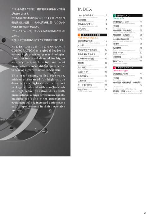
ロボットの普及が加速し、精密制御用減速機への期待 INDEX
が高まっています。
LineUp/部品構成 3 偏平タイプ D
我 も々お客様の要望に応えるべく今まで培ってきた技 LineUP / Parts configuration Flat type D
減速機構 4
術を集結し、軽量コンパクト、高減速、低バックラッシ Reduction mechanism 減速機型式 /仕様 49
部品名称/減速比 4 Reducer model / Specifications
の減速機を完成させました。 Parts name / Reduction ratio 寸法表 50
型式選定 5 Dimensions table
「フレックスウェーブ」。 チャンスの波を掴み取る想いを Model selection 寿命計算 (弾性軸受 ) 55
Life estimation (Elastic bearing)
こめて。 高トルクタイプ B2 寿命計算 (主軸受 ) 56
High torque type B2 Life estimation (Main bearing)
ロボットや工作機械の他さまざまな場面で活躍します。 入力軸の許容荷重 57
減速機型式/仕様 6 Maximum load at input shaft
Reducer model / Specifications 潤滑剤 58
N I D E C D R I V E T E C H N O L O G Y 寸法表 7 Lubricant information
Dimensions table 取付精度 59
CORPORATION is a g lobal leader in 寿命計算 (弾性軸受 ) 12 Attachment fixture requirement
Life estimation (Elastic bearing) 伝達トルク 60
various high precision gear technologies. 寿命計算 (主軸受 ) 13 Transmitting torque
Life estimation (Main bearing)
Based on increased demand for higher 注意事項 62
入力軸の許容荷重 15 Installation and assembly instructions
Maximum load at input shaft
accuracy from machine tool and robot 特性データ 63
潤滑剤 16 Characteristics data
manufacturers, we’ve utilized our expertise Lubricant information
取付精度 17 ギヤヘッドタイプ
to develop a gear reduction mechanism. Attachment fixture requirement Gearhead type
伝達トルク 18
Transmitting torque 減速機型式/仕様 71
T h i s m e c h a n i s m , c a l l e d F l e x w a v e , 入力部構造 21 Reducer model / Specifications
a d d re s s e s t h e n e e d for h i g h t orqu e Input section structure 寸法表 72
注意事項 22 Dimensions table
d e n s i t y i n a l i g h t w e i g h t , c o m p a c t Installation and assembly instructions 寿命計算(弾性軸受・主軸受)
モータ取付方法 23 77
package, combined with zero backlash Motor installation procedure Life estimation
特性データ 24 (Elastic bearing & Main bearing)
and high reduction ratios. As a result, Characteristics data 潤滑剤・伝達トルク 78
Lubricant information & Transmitting torque
manufacturers of high performance robots,
machine tools and other automation
equipment will see increased performance
and competitiveness in their respective
markets.
情熱と技術、それが駆動力
2
Page4
Line up
オープン型 Open type クローズ型 Closed type
WPU-□-□ -SDH WPC-□-□ -CR
WPU-□-□ -SRH WPC-□-□ -CD
ユニットタイプ(中空軸) Hollow unit コンポネントタイプ Component
WPU-□-□ -SRJ WPU-□-□ -CD
WPU-□-□ -CDH
ユニットタイプ(入力軸) Input shaft unit WPU-□-□ -CR
ユニットタイプ Unit
WPS-□-□ -SD
WPS-□-□ -SR WPG-□-□ -CR
簡易ユニットタイプ Simple unit ギヤヘッドタイプ Gearhead
部品構成 フレックスギヤ(薄肉・変形可能)
Parts Configuration Flex gear (thin / flexible)
カム(楕円)
Cam(elliptic)
弾性軸受(薄肉・変形可能)
Elastic bearing(thin / flexible) インタナルギヤ
Internal gear
3
Page5
0°
減速機構
Reduction Mechanism
360° 90°
・ 弾性軸受・フレックスギヤをカムによって楕円状に
変形させます。
・ 楕円長軸部分両端でフレックスギヤとインタナル
ギヤがバランス良く噛み合います。
・ インタナルギヤを固定し、カムを時計方向に360°
回転させたとき、インタナルギヤとフレックスギヤの
歯数差の分だけ、フレックスギヤが反時計方向に
回転します。
・ Flex gear and elastic bearing take elliptic
shape with the cam inserted.
・ Flex gear and internal gear are engaged
at both ends of the long axis of the ellipse 270° 180°
in a stable manner.
・ With the internal gear fixed, when the cam
(input) is rotated clockwise, the flex gear
(output) rotates counterclockwise. And
its rotational speed is determined by the
tooth count differential between two gears.
部品名称 クローズ型 オープン型
Closed type Open type
Parts Name
インタナルギヤ インタナルギヤ
Internal gear Internal gear
フレックスギヤ
Flex gear
フレックスギヤ
Flex gear
弾性軸受
Elastic bearing
楕円カム 楕円カム
Elliptic cam Elliptic cam
減速比 クローズ型 オープン型
Closed type Open type
Reduction Ratio 固定 出力
Fixed Output
固定 出力
Fix
出力 入ed力 O入u力tpu t
固定
Outpu出t 力 Input
Fi固xed定
Input
Output Fixed
-1
減速比 = 入力 出力 1
R 減速比 = 入力 出力
Reduction ratio Input Output R+1 Input Output
※入力回転方向と出力回入転力方 向が逆 ※入力回転方向と出力回入転力方 向が同じ
*The input and output rotatioIn pduirtections are opposite. *The input and output rotation Idnipreucttions are same.
-1 1
減●速R比は 減=速機仕様表の減速比R 減速比 =
RedRuc rtieonp rraetisoents the 'Ratio' figure in the specifications table on the next page. R+1
※入力回転方向と出力回転方向が逆 ※入力回転方向と出力回転方向が同じ 4
*The input and output rotation directions are opposite. *The input and output rotation directions are same.
Page6
型式選定 Model selection
型式選定の流れ
Model selection flow
減速機に掛かる負荷条件の確認
・平均出力トルク ・平均回転数 ・ラジアル荷重
・最大出力トルク ・最高回転数 ・アキシャル荷重
・モーメント荷重
Reducer operating conditions
・Average output torque ・Radial load 負荷条件の見直し
・Maximum output torque ・Axial load Re-evaluate the operation conditions
・Average rotation speed ・Moment load
・Maximum rotation speed
減速機の型式を仮選定
Temporary selection of a model
弾性軸受寿命の確認
Calculate the life span of the elastic bearing
NG
OK
主軸受寿命の確認
Calculate the life span of the main bearing
NG
OK
入力軸受荷重の確認
Calculate the load condition at the input bearing
NG
OK OK
型式の見直し
Re-evaluation of the model
減速機の型式決定
Reducer selected
NG
5
Page7
高トルク
タイプB2
High torque
type B2
High torque type B2 高トルクタイプB2
減速機型式 Reducer Model Nomenclature 仕減
様速
機
型
WP C 35 50 CR ** 式
寸
シリーズ名 タイプ サイズ 減速比 コード※1 仕様 法
Series name type Size Ratio Code Specifications 表
WPシリーズ C:コンポネントタイプ 35 50 CR 入力軸径等
Component type
寿
WP Series S:簡易ユニットタイプ 42 80
50 SR Input shaft 命
Simple unit type 計
diameter, 算
(
U:ユニットタイプ 100 etc. 弾
ユニットタイプ(入力軸) 63 性
軸
ユニットタイプ(中空軸) SRH 受
)
Unit type 80 120
寿
Input shaft unit 命
Hollow unit 100※2 160 SRJ 計
算
(
●枠番表 Availability ※1 コード詳細は寸法表をご確認ください。 主
軸
※2 ユニットタイプ(入力軸)・ユニットタイプ(中空軸)・簡易ユニットタイプのみ 受
Ratio matrix )
*1 For the code details, please check the Dimensions Table.
減速比 入
サイズ 50 80 100 120 160 *2 Unit type (input shaft unit, hollow unit), and simple unit type only. 力
35 軸
の
42 許
50 容
荷
63 重
80
100 潤
滑
剤
減速機仕様 Reducer Specifications
※ 2 ※ 3 ※ 4 ※ 5 ※ 6 ※ 7
サイズ 減速比 許容定格 許容最大 非常時最大 許容平均 許容最高
Ratio トルク トルク トルク 入力回転数 入力回転数 寿命時間 取
Size Nominal output torque Maximum output torque Emergency stop torque Nominal input speed Maximum input speed Life
R※ 1 付
[Nm] [Nm] [Nm] [r/min] [r/min] [hours] 精
50 7 23 46 度
35 80 10 30 61 3000 8500
100 10 36 70
50 21 44 91 伝
42 80 29 56 113
100 31 70 143 3000 7300 達
ト
120 31 70 112 ル
50 33 73 127 ク
80 44 96 165
50 100 52 107 191 3000 6500 入
120 52 113 191 力
160 52 120 191 部
50 51 127 242 構
80 82 178 332 10000 造
63 100 87 204 369 3000 5600
120 87 217 395 注
160 87 229 408 意
50 99 281 497 事
80 153 395 738 項
80 100 178 433 841 3000 4800
120 178 459 892
160 178 484 892 モ
50 178 523 892 ー
80 268 675 1270 タ
100 100 345 738 1400 3000 4000 取
付
120 382 802 1530 方
160 382 841 1530 法
※ 1 R値を p.4の式に入れて減速比を求めてください。 *1 Reduction ratio is to be calculated by the formula in the previous page, using R value in this table. 特
※ 2 入力回転数 2000r/minの時に許容する最大値 *2 The maximum allowable value at the input rotation speed of 2000r/min 性
※ 3 起動・停止時に許容する最大値 *3 The maximum torque when starting and stopping. デ
※ 4 衝撃等が作用した時に許容する最大値 *4 The maximum torque when it receives shock. ー
※ 5 運転中に許容する平均入力回転数の最大値 *5 The maximum average input speed. タ
※ 6 運転中に許容する入力回転数の最大値 *6 The maximum input speed.
※ 7入力回転数 2000r/min、許容定格トルク負荷時の寿命時間 *7 The life time at the input rotation speed of 2000 r/min and nominal output torque.
6
Frame size
/
Reducer Model / Dimensions Table Life estimation Life estimation Maximum load at lubricant information Attachment fixture Transmitting Torque Input section structure Installation and Motor installation Characteristics Data
Specifications (Elastic bearing) (Main bearing) input shaft requirement assembly procedure
instructions
Page8
High torque type B2 高トルクタイプB2
寸法表 Dimensions Table
クローズ型 コンポネントタイプ
Closed Type, Component
WPC- □ - □ -CR
LE
LF LM
LH LG
HD CY
CX
2-LT N-∅LU
R0.3以下
2-SV M-∅ST
∅L
A
W(JS9)
∅SA
0.5
C0.5 C
CA
CB
.5 C0 ∅SH (H7)
C0 .
SL 5
SU 2-M3x4
重量 慣性モーメント
サイズ Weight Moment of inertia
Size
kg ×10-4kgm2
35 0.10 0.0362
42 0.17 0.0831
INPUT SHAFT FOR 35&42 50 0.26 0.190
63 0.43 0.414
80 0.91 1.54
[mm]
サイズ
Size LA LB LC N LU LT LE LF LG LH LM SG SH SL W
35 44 38 50 8 3.5 M3 28.5 17.5 6 2 11 14 6 18.5 -
42 54 48 60 16 3.5 M3 32.5 20 6.5 2.5 12.5 18 8 20.7 -
50 62 54 70 16 3.5 M3 33.5 21.5 7.5 3 12 21 12 21.5 4
63 75 67 85 16 4.5 M4 37 24 10 3 13 26 14 21.6 5
80 100 90 110 16 5.5 M5 44 28 14 3 16 26 14 23.6 5
サイズ
Size T SU SA SB SD M ST SV HD CA CB CX CY CZ
35 - 2.5 17 11 23 6 4.5 M3 2.4 C0.3 C0.3 17.1 1 38
42 - 3 19 10 27.2 6 5.5 M3 3 C0.5 C0.3 19 1 45
50 13.8 - 24 16 32 8 5.5 M3 3 C0.5 C0.3 20.5 1.5 53
63 16.3 - 30 20 40 8 6.5 M4 3 C0.5 C0.3 23 1.5 66
80 16.3 - 40 26 52 8 8.8 M5 3.2 C0.5 C0.5 26.8 1.5 86
※ 1 入力部詳細については、別途寸法図にて確認ください。 *1 For details in the input section, please check the drawings.
※ 2 CX、CY、CZはケース内壁推奨寸法です。 *2 Inner dimensions of CX, CY, CZ are recommended dimensions.
7
∅LB (h6)
∅CZ
∅SD
∅SB (H6)
∅SG
∅CZ
∅LC (h6)
T
Page9
高トルク
タイプB2
High torque
type B2
仕減
様速
機
型
式
クローズ型 ユニットタイプ
Closed Type, Unit 寸
重量 慣性モーメント 法
サイズ Weight Moment of inertia 表
WPU- □ - □ -CR Size
kg ×10-4kgm2
35 0.50 0.0362
42 0.68 0.0831 寿
命
50 0.95 0.190 計
算
63 1.5 0.414 (弾
性
80 3.3 1.54 軸
受
)
LE 寿
命
LF LM 計
LH LG LK (B) 算
(主
(A) CY O-ring N-LU 軸
O-ring N-LT 受
M-ST )
入
力
∅S
A ∅L
A
軸
W(JS9) の
許
容
荷
C0.5 重
潤
滑
剤
HD
SU ∅SH (H7)
2-M3x4 CX SL 取
付
サイズ O-ring 精
Size A B 度
35 29.0× 0.5 S50
42 34.5× 0.8 S56
INPUT SHAFT FOR 35&42 50 40.64× 1.14 S67 伝
63 53.29× 0.99 S80 達
ト
80 S71 S105 ル
[mm] ク
サイズ
Size LA LB LC LD N LT LU LE LF LG LH LK LM DB SG 入
力
35 65 56 73 31 8 M4 4.5 41 27 7 3.5 2 14 38 14 部
構
42 71 63 79 38 8 M4 4.5 45 29 8 4 2 16 48 18 造
50 82 72 93 45 8 M5 5.5 45.5 28 10 5 3 17.5 56 21
注
63 96 86 107 58 10 M5 5.5 52 36 10 5 3 16 67 26 意
事
80 125 113 138 78 12 M6 6.5 62 45 12 5 3 17 90 26 項
サイズ モ
Size SH SL W T SU SA SB SC M ST HD CX CY CZ
ー
タ
35 6 18.5 - - 2.5 23 11 8 6 M4× 8 9.5 1.6 1 38 取
付
42 8 20.7 - - 3 27 10 7 6 M5× 8 9.5 1.3 1 45 方
法
50 12 21.5 4 13.8 - 32 14 10 8 M6× 9 9 1.5 1.5 53 特
63 14 21.6 5 16.3 - 42 20 15 8 M8× 10 12 3.4 1.5 66 性
デ
80 14 23.6 5 16.3 - 55 26 20 8 M10× 12 15 5.2 1.5 86 ー
タ
※ 1 入力部詳細については、別途寸法図にて確認ください。 *1 For details in the input section, please check the drawings.
※ 2 CY、CZはケース内壁推奨寸法です。 *2 Inner dimensions of CY, CZ are recommended dimensions.
8
∅LB (h7)
∅LD
∅SB (H7)
∅SC
∅SG
∅CZ
∅DB (h7)
∅LC
T
/
Reducer Model / Dimensions Table Life estimation Life estimation Maximum load at lubricant information Attachment fixture Transmitting Torque Input section structure Installation and Motor installation Characteristics Data
Specifications (Elastic bearing) (Main bearing) input shaft requirement assembly procedure
instructions
Page10
High torque type B2 高トルクタイプB2
寸法表 Dimensions Table
オープン型 簡易ユニットタイプ
Open type, Simple unit 重量 慣性モーメント
サイズ Weight Moment of inertia
Size
kg ×10-4kgm2
WPS- □ - □ -SR 35 0.39 0.0362
42 0.55 0.0831
50 0.79 0.190
63 1.3 0.414
80 2.7 1.54
100 4.5 3.11
LE
LF LM
SC LJ LH
M-∅ST LG
CY
N-LT
∅L
A
W(JS9)
CV
.
C0 5
CA ∅SH (H7)
C0.5
SU 2-M3x4 CA SL
8/12 EQUAL 16/20 EQUAL
"N-LT" "N-LT"
INPUT SHAFT FOR 35&42 ARRANGEMENT FOR 35 ARRANGEMENT FOR 42
[mm]
サイズ
Size LA LC LE LF LG LH LJ LM SG SH SL W T SU SA SB
35 44 50 28.5 23.5 6 7 14.1 5 14 6 18.5 - - 2.5 64 48
42 54 60 32.5 26.5 6.5 7.5 16 6 18 8 20.7 - - 3 74 60
50 62 70 33.5 29 7.5 8.5 17.5 4.5 21 12 21.5 4 13.8 - 84 70
63 77 85 37 34 10 12 18.7 3 26 14 21.6 5 16.3 - 102 88
80 100 110 44 42 14 15 23.4 2 26 14 23.6 5 16.3 - 132 114
100 122 135 53 51 17 18 29 2 32 16 29.7 5 18.3 - 158 140
サイズ
Size SC SD M ST CA CY CZ CV CW N LT
35 2.4 70 8 3.5 C0.4 1 38 1.7 31 8 M3× 5, φ 3.5× 6
42 3 80 12 3.5 C0.4 1 45 2.1 38 16 M3× 6, φ 3.5× 6.5
50 3 90 12 3.5 C0.4 1.5 53 2 45 16 M3× 6, φ 3.5× 7.5
63 3.3 110 12 4.5 C0.4 1.5 66 2 56 16 M4× 7, φ 4.5× 10
80 3.6 142 12 5.5 C0.4 1.5 86 2 73 16 M5× 8, φ 5.5× 14
100 4 170 12 6.6 C0.4 2 106 2 90 16 M6× 10, φ 6.6× 17
※ 1 入力部詳細については、別途寸法図にて確認ください。 *1 For details in the input section, please check the drawings.
※ 2 CV、CW、CY、CZはケース内壁推奨寸法です。 *2 Inner dimensions of CV, CW, CY, CZ are recommended dimensions.
9
∅SA
∅SD (h7)
∅SB (H7)
∅CW
∅SG
∅CZ
∅LC (h6)
∅SD (h7)
T
Page11
高トルク
タイプB2
High torque
type B2
仕減
様速
機
型
式
オープン型 ユニットタイプ(中空軸)
Open type, Unit (hollow shaft) 重量 慣性モーメント
サイズ 寸
Weight Moment of inertia
Size 法
kg ×10-4kgm2 表
WPU- □ - □ -SRH 35 0.72 0.0924
42 1.0 0.207
50 1.4 0.408 寿
命
63 2.1 1.06 計
算
80 4.2 2.72 (弾
性
100 7.2 8.66 軸
受
)
寿
命
計
算
(主
軸
受
)
入
力
軸
の
許
容
荷
重
潤
滑
剤
取
付
精
度
伝
達
ト
ル
ク
[mm]
入
サイズ
Size LA LB LC LD LE LF LG LH LJ LK LL LP LQ LR 力
部
35 44 36 54 70 52.5 20.5 12 20 7.5 8 9 2.5 5.5 6.5 構
造
42 54 45 64 80 56.5 23 12 21.5 8.5 8.5 10 2.5 5.5 6.5
50 62 50 75 90 51.5 25 5 21.5 7 9 10.5 - - - 注
意
63 77 60 90 110 55.5 26 6 23.5 6 8.5 10.5 - - - 事
項
80 100 85 115 142 65.5 32 7 26.5 5 9.5 12 - - -
100 122 100 140 170 79 38 8 33 7 13 14 - - -
モ
ー
サイズ タ
Size SA SB SC SD SE SF M ST SU N LT 取
35 64 - 14 20 74 36 8 3.5 M3 8 M3× 5, φ 3.5× 11.5 付
方
42 74 - 19 25 84 45 12 3.5 M3 16 M3× 6, φ 3.5× 12 法
特
50 84 25.5 21 30 95 - 12 3.5 M3× 6 16 M3× 6, φ 3.5× 13.5 性
63 102 33.5 29 38 115 - 12 4.5 M3× 6 16 M4× 7, φ 4.5× 15.5 デ
ー
80 132 40.5 36 45 147 - 12 5.5 M3× 6 16 M5× 8, φ 5.5× 20.5 タ
100 158 52 46 59 175 - 12 6.6 M4× 8 16 M6× 10, φ 6.6× 25
10
/
Reducer Model / Dimensions Table Life estimation Life estimation Maximum load at lubricant information Attachment fixture Transmitting Torque Input section structure Installation and Motor installation Characteristics Data
Specifications (Elastic bearing) (Main bearing) input shaft requirement assembly procedure
instructions
Page12
High torque type B2 高トルクタイプB2
寸法表 Dimensions Table
オープン型 ユニットタイプ(入力軸)
Open type, Unit (input shaft) 重量 慣性モーメント
サイズ Weight Moment of inertia
Size
kg ×10-4kgm2
WPU- □ - □ -SRJ 35 0.65 0.0266
42 0.91 0.0666
50 1.4 0.155
63 2.1 0.382
80 4.1 1.28
100 6.9 3.15
[mm]
サイズ
Size LA LB LC LD LE LF LG LH LJ LK LL LP LQ LR
35 44 36 54 70 50.5 20.5 15 15 2.5 8 9 11 - -
42 54 45 64 80 56 23 17 16 3 8.5 10 12 - -
50 62 50 75 90 63.5 25 21 17.5 3 9 10.5 - 16.5 20
63 77 60 90 110 72.5 26 26 20.5 3 8.5 10.5 - 22.5 25
80 100 85 115 142 84.5 32 26 26.5 5 9.5 12 - 22.5 25
100 122 100 140 170 100 38 31 31 5 13 14 - 27.5 30
サイズ
Size SA SB SC SE SV SW M ST SU N LT
35 64 6 - 74 - - 8 3.5 - 8 M3× 5, φ 3.5× 11.5
42 74 8 - 84 - - 12 3.5 - 16 M3× 6, φ 3.5× 12
50 84 10 8.2 95 3 3 12 3.5 M3× 6 16 M3× 6, φ 3.5× 13.5
63 102 14 11 115 5 5 12 4.5 M5× 10 16 M4× 7, φ 4.5× 15.5
80 132 14 11 147 5 5 12 5.5 M5× 10 16 M5× 8, φ 5.5× 20.5
100 158 16 13 175 5 5 12 6.6 M5× 10 16 M6× 10, φ 6.6× 25
11
Page13
高トルク
タイプB2
High torque
type B2
寿命計算(弾性軸受)Life estimation (Elastic bearing) 仕減
様速
機
型
式
弾性軸受寿命計算
Life span for the elastic bearing 寸
法
表
運転パターン T1
Operation cycle example 負荷トルク T2
Working torque T3 T4 寿
命
時間 計
Time 算
(弾
性
n 軸
n 2
1 n3 受
)
寿
出力回転数 n4 命
Output rotation t 計
speed t1 2 t3 t4 時間 算
Time (主
軸
受
①平均出力トルク・最大出力トルクの算出 )
入
Calculation formula for output torque 力
軸
の
許
3 3 3 容
平均出力トルク n 2 t2 T2 n
ao 3 1 t1 T1 n n t
T n Tn 荷
Average output torque Tao Nm
n 重
1 t 1 n2 t 2 n n t n
潤
滑
最大出力トルク Tmo = T1 , T2 , ・・・ Tn の最大値 剤
Peak output torque value Tmo Nm Tmo = Largest among T1, T2, … Tn
最大出力トルクが許容最大出力以下であることをご確認ください。
Please make sure the peak output torque is below the maximum output torque in the specification table. 取
付
②平均入力回転数・最高入力回転数の算出 精
度
Calculation formula for input speed
平均出力回転数 2 t2 nn tn 伝
Average output rotation speed nao r/min nao n1 t1 n
t 達
1 t2 tn ト
ル
ク
最高出力回転数 nmo = n1, n2 , ・・・ n n の最大値
Peak output rotation speed nmo r/min
nmo = Largest among n1, n2, … nn
入
力
平均入力回転数 部
Average input speed nai r/min nai = nao × R (R = 減速比 )(R = ratio) 構
造
最高入力回転数
Peak input speed value nmi r/min nmi = nmo × R (R = 減速比 )(R = ratio) 注
意
最高入力回転数が許容最高入力回転数以下であることをご確認ください。 事
項
Please make sure the peak input speed value is below the maximum input speed in the specification table.
③寿命時間の計算
モ
Calculation formula for life span ー
タ
取
弾性軸受寿命時間 Tar 3 nar 付
Part life span for the elastic bearing Lhe h Lhe 10000 方
Tao nai 法
特
定格トルク 性能表の許容定格トルク 性
Rating torque Tar Nm
Nominal output torque in the specification table デ
ー
タ
定格入力回転数
Rating input rotation speed nar r/min 2000 r/min
12
/
Reducer Model / Dimensions Table Life estimation Life estimation Maximum load at lubricant information Attachment fixture Transmitting Torque Input section structure Installation and Motor installation Characteristics Data
Specifications (Elastic bearing) (Main bearing) input shaft requirement assembly procedure
instructions
Page14
High torque type B2 高トルクタイプB2
寿命計算(主軸受)Life estimation (Main bearing )
主軸受仕様(クロスローラ軸受)Main bearing specification(Cross roller bearing)
コロのピッチ円径 オフセット量 基本動定格荷重 基本静定格荷重 許容モーメント モーメント剛性
シリーズ サイズ Pitch circle diameter Offset Basic dynamic Basic static load Allowable Moment
of the bearing rollers load rating rating moment rigidity
Series Size
Dm L C Co Mal Km
m m N N Nm ×104 Nm/rad
35 0.0350 0.0095 4700 6070 41 4.38
42 0.0425 0.0095 5290 7550 64 7.75
WPU-□-□-CR 50 0.0500 0.0095 5780 9000 91 12.8
63 0.0620 0.0115 9600 15100 156 24.2
80 0.0800 0.0130 15000 25000 313 53.9
35 0.0500 0.0162 5800 8600 74 8.5
42 0.0600 0.0184 10400 16300 124 15.4
50 0.0700 0.0195 14600 22000 187 25.2
WPS-□-□-SR
63 0.0850 0.0241 21800 35800 258 39.2
80 0.111 0.0299 38200 65400 580 100
100 0.133 0.0360 43300 81600 849 179
35 0.0500 0.0217 5800 8600 74 8.5
42 0.0600 0.0239 10400 16300 124 15.4
WPU-□-□-SRH 50 0.0700 0.0255 14600 22000 187 25.2
WPU-□-□-SRJ 63 0.0850 0.0296 21800 35800 258 39.2
80 0.111 0.0364 38200 65400 580 100
100 0.133 0.0440 43300 81600 849 179
主軸受寿命計算 Fr1
Life span for the main bearinFgr Fr
1 2
Fr2 ラジアル荷重 Fr4
運転パターン Radial load 時間
Fr Fr
4 3 Time
Operation cycle example Fr3
Fa1
Fa Fa
1 2
Fa アキシャル荷重 Fa
2 4
Axial load 時間
Fa Fa
4 3 Time
Fa3
n
n 2
1 n3
n
n 2
1 出n力3 回転数 n4
Output rotation 時間
speed n4 t1 t2 t3 t4 Time
t1 t2 t3 t4
外部負荷 L
External load L L
Lr L L
r L L
L L
Fr
Fr
Fa
Fa
13
La
Dm
La
DDmm
Dm
Dm
Dm
Dm
Dm
Page15
高トルク
タイプB2
High torque
type B2
Life estimation (Main bearing ) 寿命計算(主軸受)Life estimation (Main bearing ) 仕減
様速
機
型
①最大負荷モーメントの算出 式
Calculation formula for the largest working moment
寸
法
最大負荷モーメント 表
Peak working moment Mm Nm Mm = Frm・(Lr + L ) + Fam・La
最大ラジアル荷重 Frm = Fr1, Fr2・・・ Frn の最大値
Peak radial load Frm N
Frm = Largest among Fr1, Fr2, … Frn 寿
命
最大アキシャル荷重 Fam = Fa1, Fa2,・ ・・ Fan の最大値 計
Peak axial load Fam N 算
Fam = Largest among Fa1, Fa2, … Fan (弾
性
最大負荷モーメントが許容モーメント以下であることをご確認ください。 軸
受
Please make sure the peak working moment is below the maximum allowable moment. )
寿
命
計
算
(
②平均ラジアル荷重・平均アキシャル荷重・平均出力回転数・平均負荷モーメントの算出 主
軸
受
Calculation formula for the Average radial load, Axial load, Average output rotation speed, )
Average working moment 入
力
軸
10 10 10 の
平均ラジアル荷重 許
Average radial load Fra N a 10 n
3 1 t Fr 3 n2 t2 Fr 3
1 1 nn t Fr 3
Fr 2 n n 容
n 荷
1 t 1 n2 t 2 n n t n 重
10 10 10 潤
平均アキシャル荷重 3
Fa 10 n1 t 3 3
a 3 1 Fa1 n2 t2 Fa nn t
2 n Fan 滑
Axial load Faa N
n 剤
1 t 1 n2 t 2 n n t n
平均出力回転数
Average output rotation speed nao r/min nao n1 t1 n2 t2 nn tn
t1 t2 tn 取
付
精
平均負荷モーメント 度
Average working moment Ma Nm Ma = Fra・(Lr + L ) + Faa・La
伝
達
③荷重係数・動等価ラジアル荷重の算出 ト
ル
Calculation formula for the Loading factor, Equivalent radial load ク
F a a ≦ 1 . 5 の場合、 Xc = 1.0 , Yc = 0.45 入
Fra 2Ma / Dm 力
荷重係数 部
Loading factor Xc, Yc - 構
Faa 造
> 1 . 5 の場合、 Xc = 0.67 , Yc = 0.67
Fra 2Ma / Dm
注
意
動等価ラジアル荷重 事
Equivalent radial load Pc N Pc = Xc・(Fra + 2Ma/Dm) + Yc・Faa
項
④主軸受の寿命時間の計算 モ
ー
Life span for the main bearing タ
取
10 付
主軸受寿命時間 方
Life span for the main bearing Lhc h 106 C 3
Lhc 法
60 nao fw Pc
特
1.0 : 衝撃を伴わない場合 no shock 性
デ
衝撃係数 ー
Impact factor fw - 1.2 : 多少の衝撃を伴う場合 with some shock タ
1.5 : 振動衝撃を伴う場合 with shock and vibration
14
/
Reducer Model / Dimensions Table Life estimation Life estimation Maximum load at lubricant information Attachment fixture Transmitting Torque Input section structure Installation and Motor installation Characteristics Data
Specifications (Elastic bearing) (Main bearing) input shaft requirement assembly procedure
instructions
Page16
High torque type B2 高トルクタイプB2
入力軸の許容荷重 Maximum load at input shaft
軸受仕様(オープン型、ユニットタイプ)Bearing specification (Open type, Unit)
ベアリング A ベアリング B
Bearing A Bearing B
シリーズ サイズ 基本動定格荷重 基本静定格荷重 基本動定格荷重 基本静定格荷重 a b
Series Size Basic dynamic load rating Basic static load rating Basic dynamic load rating Basic static load rating
C Co C Co
N N N N mm mm
35 4000 2470 4000 2470 16.5 26.5
42 4300 2950 4300 2950 17.5 29.5
50 4500 3450 4500 3450 16 26
WPU-□-□-SRH
63 4900 4350 4900 4350 17 29
80 14100 10900 5350 5250 20 35.5
100 16400 14300 11500 10900 24 43
35 2240 910 1080 430 24.5 21
42 2700 1270 1610 710 27.5 23
50 4350 2260 2240 910 32.3 25.2
WPU-□-□-SRJ
63 5600 2830 2700 1270 37.3 29.2
80 9400 5000 4350 2260 39.4 38.1
100 13200 8300 6000 3250 48.5 42
ベアリングA ベアリングA
Bearing A Bearing A
ベアリングB ベアリングB
Bearing B Bearing B
a b a b
許容荷重(平均入力回転数:2000r/min、寿命時間:10000h)
Maximum load (Average input rotation speed : 2000r/min, Life span : 10000h)
800 WPU-□ -□ -SRH 35 500 35
42 WPU-□ -□ -SRJ
35 4325
700 450
50 42 600 5402
600 1000 63 50 400 6530
63 63
80 350500
80 8800
500 800 100 300 100
400
400 250
600
300 200300
150
200 400
100200
100 50
200 100
0 0
0 0 100 200 300 400 0 100 200 300
0
0 200 400 600 800 0 200 400 600
アキシャル荷重 Fa [N] アキシャル荷重 Fa [N]
Axial load Axial load
15
ラジアル荷重 Fr [N]
Radial load
ラジアル荷重 Fr [N]
Radial load
Page17
高トルク
タイプB2
High torque
type B2
潤滑剤 lubricant information 仕減
様速
機
型
式
使用グリース
Grease 寸
法
スミプレックスSFB No.1(住鉱潤滑剤株式会社)Sumiplex SFB No.1 (SUMICO LUBRICANT CO., LTD.) 表
使用温度範囲 : 0~40℃(周囲温度)Operating temperature range:0-40℃ (ambient temperature)
寿
命
グリース塗布 計
算
Grease application (弾
性
軸
以下の通り、減速機各部にグリースを塗布してください。 受
Please apply grease according to the table below. )
寿
命
グリース塗布量 Grease application 計
算
・塗布箇所Cは、減速機の取付姿勢(出力側が横向き、上向き、下向き)により塗布量を変更してください。 (主
軸
( グリース封入済みのユニットタイプは、C(横向き)のグリース量が充填されています。) 受
)
・入力ASSY~ケース内壁に空間の50%のグリースを充填してください。 入
力
・ケース設計によりグリースが不足する場合は、弊社までお問い合わせください。 [g] 軸
の
許
・ The quantity of grease applied to C should 塗布箇所 Applied part 容
be adjusted depending on the mounting 荷
サイズ 重
direction. C C C
Size
C of the unit type product is already A B (横向き) (上向き) (下向き) D 潤
filled with the same quantity of grease as Horizontal Vertical up Vertical down 滑
剤
horizontal mounting. 35 0.3 0.3 6 8 9 0.3
・ 50% of the space between input assy 42 0.5 0.5 10 12 14 0.5
and casing inner wall should be filled with 50 0.8 0.8 16 18 21 0.8
grease. 63 1.5 1.5 30 35 40 1.5 取
・ If the amount of grease is not sufficient 80 3.0 3.0 60 70 80 3.0 付
due to case design, please contact us. 精
100 4.5 4.5 120 140 160 4.5 度
グリース塗布部 Grease application location
WPC-□ -□ -CR WPU-□ -□ -CR WPS-□ -□ -SR 伝
達
ト
ル
ク
(横向き) 入
力
Horizontal Pre-applied 部
構
造
注
意
ケース
Casing ケース 空間の50%を充填 事
空間の50%を充填 項
Fill 50% of the gap in volume ケース 空間の50%を充填
(下向き)
Vertical
down モ
ー
タ
取
入力 ASSY 入力 ASSY 入力 ASSY 付
input section assembly 方
入力 ASSY 入力 ASSY 法
入力 ASSY
input section assembly 特
性
(上向き) デ
Vertical ー
up タ
ケース 空間の50%を充填 ケース ケース
空間の50%を充填 空間の50%を充填
16
/
Reducer Model / Dimensions Table Life estimation Life estimation Input shaft max. load lubricant information Attachment fixture Transmitting Torque Input section structure Installation and Motor installation Characteristics Data
Specifications (Elastic bearing) (Main bearing) requirement assembly procedure
instructions
Page18
High torque type B2 高トルクタイプB2
取付精度 Attachment fixture requirement
取付精度 Attachment fixture requirement
WPC-□ -□ -CR
Casing Input
section
Output
section
取付精度 [mm]
サイズ
Size 35 42 50 63 80
a 0.015 0.015 0.018 0.018 0.023
b 0.010 0.012 0.014 0.016 0.020
c 0.013 0.013 0.015 0.018 0.020
d 0.015 0.015 0.018 0.018 0.023
e 0.015 0.015 0.018 0.018 0.023
f 0.012 0.012 0.014 0.016 0.016
g 0.016 0.020 0.024 0.024 0.024
WPU-□ -□ -CR WPS-□ -□ -SR
Casing
Input
section
取付精度 [mm] 取付精度 [mm]
サイズ
Size 35 42 50 63 80 サイズ
Size 35 42 50 63 80 100
a 0.020 0.020 0.020 0.025 0.025 a 0.025 0.025 0.025 0.030 0.030 0.036
b 0.012 0.012 0.014 0.016 0.016 b 0.020 0.020 0.020 0.025 0.025 0.027
c 0.016 0.020 0.024 0.024 0.024 c 0.020 0.020 0.020 0.025 0.025 0.025
d 0.012 0.012 0.014 0.016 0.016 0.016
e 0.016 0.020 0.024 0.024 0.024 0.024
17
Recommended
tolerance
Recommended
tolerance
Recommended
tolerance
Recommended tolerance
Page19
高トルク
タイプB2
High torque
type B2
伝達トルク Transmitting Torque 仕減
様速
機
型
式
ボルト取付
Bolting 寸
法
ボルトの締付トルクは下表の通りです。 表
ボルト本数や締付トルクにて伝達可能なトルクが異なりますのでご注意ください。
Please refer to the table below for the bolt tightening torque.
Please be noted that the transmittable torque varies depending on the bolt count and tightening torque. 寿
命
計
算
(弾
ボルト締付トルク 性
軸
受
Tightening torque for bolts )
寿
命
ボルトサイズ Bolt size M3 M4 M5 M6 M8 M10 推奨ボルト : 強度区分 12.9 以上 計
締付トルク[Nm]Tightening torque 1.9 4.3 8.7 15 36 71 Recommended bolt : 算
(
Strength rating above 12.9 主
軸
受
)
入
力
軸
伝達トルク(クローズ型、ユニットタイプ) の
許
容
Bolt specifications and Transmitting torque (Closed type, Unit) 荷
重
出力フランジ取付 Output flange attachment 潤
サイズ Size 35 42 50 63 80 滑
剤
ボルトサイズ Bolt size M4 M5 M6 M8 M10
ボルト本数 Bolt count 6 6 8 8 8
取付 PCD[mm]Bolt PCD 23 27 32 42 55
締付トルク[Nm]Tightening torque 4.3 8.7 15 36 71 取
伝達トルク[ Nm]Transmitting torque 56 106 238 566 1177 付
精
度
インタナルギヤ取付(CR)Internal gear attachment
サイズ Size 35 42 50 63 80
ボルトサイズ Bolt size M4 M4 M5 M5 M6 伝
ボルト本数 達
Bolt count 8 8 8 10 12 ト
取付 PCD[mm]Bolt PCD 65 71 82 96 125 ル
締付トルク[Nm]Tightening torque 4.3 4.3 8.7 8.7 15 ク
伝達トルク[ Nm]Transmitting torque 210 230 430 629 1392
入
力
部
構
Internal gear attachment 造
注
意
事
項
Output flange モ
attachment ー
タ
取
付
方
法
特
性
デ
ー
タ
18
/
Reducer Model / Dimensions Table Life estimation Life estimation Maximum load at lubricant information Attachment fixture Transmitting Torque Input section structure Installation and Motor installation Characteristics Data
Specifications (Elastic bearing) (Main bearing) input shaft requirement assembly procedure
instructions
Page20
High torque type B2 高トルクタイプB2
伝達トルク Transmitting Torque
伝達トルク(クローズ型、コンポネントタイプ)
Bolt specifications and Transmitting torque (Closed type, Component)
フレックスギヤ取付 Flex Gear Attachment
サイズ Size 35 42 50 63 80
ボルトサイズ Bolt size M4 M5 M5 M6 M8
ボルト本数 Bolt count 6 6 8 8 8
取付 PCD[mm]Bolt PCD 17 19 24 30 40
締付トルク[Nm]Tightening torque 4.3 8.7 8.7 15 36
伝達トルク[ Nm]Transmitting torque 41 75 126 223 539
インタナルギヤ取付(CR)Internal Gear Attachment
サイズ Size 35 42 50 63 80
ボルトサイズ Bolt size M3 M3 M3 M4 M5
ボルト本数 Bolt count 8 16 16 16 16
取付 PCD[mm]Bolt PCD 44 54 62 75 100
締付トルク[Nm]Tightening torque 1.9 1.9 1.9 4.3 8.7
伝達トルク[ Nm] Transmitting torque 82 200 230 485 1048
Internal gear attachment
Flex gear attachment
◆ピン穴の追加 Reinforcement
フレックスギヤ取付の伝達トルクが要求を満たさない場合は、ピンの併用をお願いします。
ピン穴はオプションで追加可能です。
Pins can be added if the transmittable torque at the flex gear interface is not sufficient.
As an option, holes can be added.
Thru hole for pins
Forcing tap
WP-35, 42 WP-50, 63, 80
19