


アルミ電解コンデンサ(ラジアルリード、SMD、スナップイン、スクリューターミナル)、有機導電性ポリマーコンデンサ等
Lelonは1976年に設立された台湾のアルミ電解コンデンサのメーカーです。Lelonは、アルミ電解コンデンサ(ラジアルリード、SMD、スナップイン、スクリューターミナル)と有機導電性ポリマーコンデンサを含む電解コンデンサの多様な製品ラインを有しています。Lelonの製品は、自動車エレクトロニクス、通信、クラウドコンピューティング、パワーエレクトロニクスのハイエンド分野で幅広く使用されています。
有機導電性ポリマーコンデンサ(op-cap)
導電性高分子ハイブリッドコンデンサ
SMDアルミニウム電解
鉛アルミ電解
難燃性
リード付きミニチュアアルミニウム電解
スナップインアルミニウム電解
ネジ端子アルミニウム電解
鉛二極アルミニウム電解
軸タイプアルミニウム電解
EDLC
◇メーカーサイト
http://www.lelon.com/en/index.php
このカタログについて
| ドキュメント名 | Lelon Electronics レロン 立隆電子 (台湾) 電解コンデンサ カタログ |
|---|---|
| ドキュメント種別 | 製品カタログ |
| ファイルサイズ | 18.6Mb |
| 登録カテゴリ | |
| 取り扱い企業 | 二松電気株式会社 (この企業の取り扱いカタログ一覧) |
この企業の関連カタログ


このカタログの内容
Page1
Product Guide
Contents
● Product Guide 2 - 27
1. Product Group Chart ............................................................................................................... 2
2. Capacitor Series Table ............................................................................................................ 5
3. Precautions and Guidelines for Using Conductive Polymer Hybrid Capacitors and Aluminum Electrolytic Capacitors ... 7
4. Precautions and Guidelines for Using Organic Conductive Polymer Capacitors .................. 10
5. Part Numbering System (Radial Type) .................................................................................. 13
6. Part Numbering System (SMD Type) .................................................................................... 15
7. Part Numbering System (Snap-in Type) ................................................................................ 16
8. Part Numbering System (Screw Type) .................................................................................. 17
9. Taping Specifications for SMD Type...................................................................................... 18
10. Taping Specifications for Radial Type of OP-CAP ................................................................. 20
11. Lead Cutting Specifications for Radial Type of OP-CAP ....................................................... 20
12. Taping Specifications for Radial Type ................................................................................... 21
13. Lead Forming and Cutting Specifications for Radial Type ..................................................... 22
14. Package Quantity .................................................................................................................. 23
15. Terminal Codes for Snap-in Type .......................................................................................... 25
16. Reflow Conditions for SMD Type .......................................................................................... 26
17. Anti-vibration Structure for SMD Type ................................................................................... 27
18. Discontinued Series .............................................................................................................. 27
● Organic Conductive Polymer Capacitors (OP-CAP) 28 - 82
1. OP-CAP Item List .................................................................................................................... 28
2. Product Specifications for SMD Type………………………………...……..…..…….……………34
3. Product Specifications for Radial Type…………….….………..……...……...……...……………60
● Conductive Polymer Hybrid Capacitors 83 - 90
1. Hybrid Product Specifications for SMD Type………..…………….……….........…..……..….…..83
2. Hybrid Product Specifications for Radial Type…...……………….……….........…..….…..……..87
● SMD Aluminum Electrolytic Capacitors 91 - 127
1. Product Specifications……..………………………..……………….……….........…..…..………...91
● Aluminum Electrolytic Capacitors 128 - 267
1. Product Specifications for Radial Type…………….…...…….……………….....………..……...128
2. Product Specifications for Snap-in Type......……………….………………………………..……186
3. Product Specifications for Screw Terminal Type…..…………………………….………..……..237
※Quality and Environmental Management System
All product speciications in the catalog are subject to change without notice. (CAT. 2020E1) 1
1
Contents
Page2
Product Guide
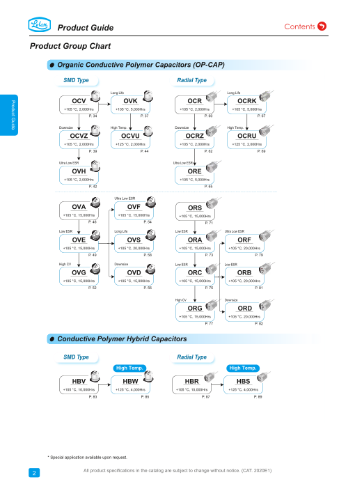
Product Group Chart
Organic Conductive Polymer Capacitors (OP-CAP)
SMD Type Radial Type
Long Life Long Life
OCV OVK OCR OCRK
+105 °C, 2,000Hrs +105 °C, 5,000Hrs +105 °C, 2,000Hrs +105 °C, 5,000Hrs
P. 34 P. 37 P. 60 P. 67
Downsize High Temp. Downsize High Temp.
OCVZ OCVU OCRZ OCRU
+105 °C, 2,000Hrs +125 °C, 2,000Hrs +105 °C, 2,000Hrs +125 °C, 2,000Hrs
P. 39 P. 44 P. 62 P. 69
Ultra Low ESR Ultra Low ESR
OVH ORE
+105 °C, 2,000Hrs +105 °C, 5,000Hrs
P. 42 P. 65
Ultra Low ESR
OVA OVF ORS
+105 °C, 15,000Hrs +105 °C, 15,000Hrs +105 °C, 15,000Hrs
P. 46 P. 54 P. 71
Low ESR Long Life Low ESR Ultra Low ESR
OVE OVS ORA ORF
+105 °C, 15,000Hrs +105 °C, 20,000Hrs +105 °C, 15,000Hrs +105 °C, 20,000Hrs
P. 49 P. 58 P. 73 P. 79
High CV Downsize Low ESR Low ESR
OVG OVD ORC ORB
+105 °C, 15,000Hrs +105 °C, 15,000Hrs +105 °C, 15,000Hrs +105 °C, 20,000Hrs
P. 52 P. 56 P. 75 P. 81
High CV Downsize
ORG ORD
+105 °C, 15,000Hrs +105 °C, 20,000Hrs
P. 77 P. 82
* Please refer to the life calculation on page 12
Conductive Polymer Hybrid Capacitors
SMD Type Radial Type
High Temp. High Temp.
HBV HBW HBR HBS
+105 °C, 10,000Hrs +125 °C, 4,000Hrs +105 °C, 10,000Hrs +125 °C, 4,000Hrs
P. 83 P. 85 P. 87 P. 89
* Special application available upon request.
* Special application available upon request.
2 All product speciications in the catalog are subject to change without notice. (CAT. 2020E1)
2
Product Guide
Page3
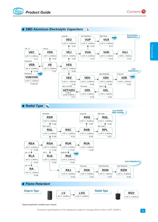
Product Guide
SMD Aluminum Electrolytic Capacitors
Automative
Long Life Low Impedance High Temp
New Application
VEU VUP VUX
+105 °C, 5,000Hrs +125 °C, 3,000Hrs +135 °C, 2,000Hrs
P. 97 P.115 P.117
Low LC 4.5mmL
VEC VSS VEJ VUA VUK VUJ
+85 °C, 2,000Hrs +85 °C, 2,000Hrs +105 °C, 2,000Hrs +125 °C, 2,000Hrs +125 °C, 5,000Hrs +150°C, 1,000Hrs
P.127 P. 93 P. 95 P.113 P.119 P.121
Bi-polarized
VEB VE VES
+85 °C, 2,000Hrs +85 °C, 2,000Hrs +105 °C, 1,000Hrs Low
P.123 P. 91 P. 94 Impedance
Bi-polarized New High Reliability Long Life
VGB/VGN NewVEZ VEH VZH VZR
+105 °C, 2,000Hrs +105 °C, 1,000Hrs +105 °C, 2,000Hrs +105°C, 5,000Hrs +105°C, 7,000Hrs
P.124/125 P. 99 P.100 P.102 P.105
Ultra Low ESR Downsize High CV
VZT/VZU VZS VZL
+105°C,
+105°C, 2,000Hrs +105°C, 2,000Hrs
2,000~5,000Hrs
P.111 P.109 P.107
Radial Type
Low Profile
High Voltage
Downsize Long Life Slim Type
RXR RXQ RQL
+105 °C, 2,000Hrs +105 °C, 10,000Hrs +105 °C, 10,000Hrs
P.165 P.157 P.163
Slim Type Slim Type
RGL RXC RXB RPL
+105 °C, 2,000Hrs +105 °C, 3,000Hrs +105 °C, 5,000Hrs +105 °C, 5,000Hrs
P.159 P.153 P.155 P.161
REA RGA RUK RUA
+85 °C, 2,000Hrs +105 °C, 2,000Hrs +125 °C, 5,000Hrs +130°C, 3,000Hrs
page 12 P.128 P.130 P.134 P.138
Low LC -55°C Hight R.C.
New
RLA RJA RUZ
+85 °C, 2,000Hrs +105 °C, 2,000Hrs +125 °C, 5,000Hrs
Low Impedance
P.167 P.132 P.136
Low LC Downsize High Reliability High Reliability
RA
RXJ RXK RXW RZW
+105 °C, 1,000Hrs
+105 °C, 5,000Hrs +105 °C, 5,000Hrs +105 °C, 7,000Hrs +105 °C, 10,000Hrs
P.169
P.140 P.143 P.147 P.150
Flame Retardant
Snap-in Type Radial Type
LV LVG RGV
+85 °C, 2,000Hrs +105 °C, 2,000Hrs +105 °C, 2,000Hrs
* Special application available upon request.
n request. * Special application available upon request.
All product speciications in the catalog are subject to change without notice. (CAT. 2020E1)
3
2 3
Product Guide
Page4
Product Guide
Product Group Chart
Ra dial - 7mmL and 5mmL
μ
Low Leakage Standard Wide Tempature
Range
SA SLA SEA SG
+105 °C, 1,000Hrs +85 °C, 2,000Hrs +85 °C, 2,000Hrs +105 °C, 1,000Hrs SJA
P.174 P.173 P.171 P.172 +105 °C, 2,000Hrs
5mmL 5mmL 5mmL P.175
SSL SS SSG Low ESR
+85 °C, 1,000Hrs +85 °C, 1,000Hrs +105 °C, 1,000Hrs
SXJ
P.178 P.176 P.177
+105 °C, 1,000Hrs
P.179
Snap-in Terminal
Standard High Ripple Current Over Voltage Vent
Operation
LS LSR
LS2
+85 °C, 3,000Hrs +105 °C, 3,000Hrs
+85 °C, 2,000Hrs
P.186 P.220
P.197
105°C, Long Life Charge/Discharge
LSG Application
+105 °C, 2,000Hrs LSM LSK LSP
P.203 +105 °C, 3,000Hrs +105 °C, 5,000Hrs +105 °C, 7,000Hrs LHM
15mmL P.212 P.223 P.229 +105 °C, 50M Time
New
LSL P.233 μ
+105 °C, 2,000Hrs
P.200
Screw Terminal Bi-polarized
Standard Long Life Longer Life
RN RNG
MEA MEK MEQ +85 °C, 2,000Hrs +105 °C, 2,000Hrs
μ
+85 °C, 2,000Hrs +85 °C, 5,000Hrs +85 °C, 20,000Hrs P.180 P.182
P.237 P.24p8age 12 P.253 7mmL 5mmL
Charge/Discharge SN SSN
MGA MGK Application +85 °C, 1,000Hrs +85 °C, 1,000Hrs
+105 °C, 2,000Hrs +105 °C, 5,000Hrs
P.184 P.185
equest.
P.257 P.263 MKR
* Special application available upon request.
+85 °C, 50M Times
P.266
Axial
Standard Soldering Star
High Reliability High Temperature High RC High Reliability High Temperature High RC
TUK TUP TUR TSK TSP TSR
+125 °C, 5,000Hrs +150°C, 2,000Hrs +125 °C, 10,000Hrs +125 °C, 5,000Hrs +150°C, 2,000Hrs +125 °C, 10,000Hrs
Note: Axial type is not included in this catalog.
n requetaslto.g.
4 2 All product speciications in the catalog are subject to change without notice. (CAT. 2020E1)4
2
Product Guide
Page5
Product Guide
Capacitor Series Table
● Organic Conductive Polymer Capacitors (OP-CAP)
Temperature & Rated Voltage Capacitance
Series Features Page
Endurance Range (V, DC) Range(μF)
OCV Standard 105℃, 2,000 Hrs 2.5 ~ 35 6.8 ~ 1,500 34
OVK Long Life 105℃, 5,000 Hrs 4 ~ 35 18 ~ 820 37
OCVZ Downsize, Super Low ESR 105℃, 2,000 Hrs 2.5 ~ 35 22 ~ 2,700 39
OVH Ultra Low ESR 105℃, 2,000 Hrs 2.5 ~ 6.3 220 ~ 2,200 42
OCVU High Temperature Usage, 125℃ 125℃, 1,000 ~ 2,000 Hrs 2.5 ~ 16 180 ~ 1,500 44
SMD
OVA Standard 105℃, 15,000 Hrs 2.5 ~ 25 100 ~ 1,500 46
Type
OVE Low ESR 105℃, 15,000 Hrs 2.5 ~ 16 33 ~ 2,700 49
OVG 16 ~ 25V 105℃, 15,000 Hrs 16 ~ 25 22 ~ 1,000 52
OVF Ultra Low ESR 105℃, 15,000 Hrs 2.5 ~ 6.3 220 ~ 680 54
OVD Down Size 105℃, 15,000 Hrs 2.5 ~ 16 100 ~ 560 56
OVS Long Life 105℃, 20,000 Hrs 4 ~ 16 22 ~ 560 58
OCR Standard 105℃, 2,000 Hrs 2.5 ~ 35 6.8 ~ 1,500 60
OCRZ Downsize, Super Low ESR 105℃, 2,000 Hrs 2.5 ~ 25 100 ~ 2,700 62
ORE Ultra Low ESR, Long Life 105℃, 5,000 Hrs 2.5 ~ 35 22 ~ 2,700 65
OCRK Long Life 105℃, 5,000 Hrs 2.5 ~ 35 68 ~ 820 67
OCRU High Temperature Usage, 125℃ 125℃, 1,000 ~ 2,000 Hrs 2.5 ~ 20 100 ~ 1,200 69
Radial ORS Standard 105℃, 15,000 Hrs 2.5 ~ 35 18 ~ 1,200 71
Type ORA Low ESR 105℃, 15,000 Hrs 2.5 ~ 16 47 ~ 1,500 73
ORC Low ESR, High Capacitance 105℃, 15,000 Hrs 2.5 ~ 16 270 ~ 2,700 75
ORG 16 ~ 35V 105℃, 15,000 Hrs 16 ~ 35 56 ~ 2,200 77
ORF Long Life, Low ESR 105℃, 20,000 Hrs 2.5 ~ 16 100 ~ 820 79
ORB Long Life 105℃, 20,000 Hrs 2.5 ~ 6.3 470 ~ 820 81
ORD Long Life, Down Size 105℃, 20,000 Hrs 2.5 ~ 6.3 270 ~ 560 82
● Conductive Polymer Hybrid Capacitors
Temperature & Rated Voltage Capacitance
Series Features Page
Endurance Range (V, DC) Range(μF)
SMD HBV Ultra Low ESR, Long Life 105℃, 10,000 Hrs 16 ~ 80 10 ~ 470 83
Type HBW High Temperature Usage, 125℃ 125℃, 4,000 Hrs 16 ~ 63 10 ~ 470 85
Radial HBR Ultra Low ESR, Long Life 105℃, 10,000 Hrs 16 ~ 80 10 ~ 470 87
Type HBS High Temperature Usage, 125℃ 125℃, 4,000 Hrs 16 ~ 63 10 ~ 470 89
● SMD Aluminum Electrolytic Capacitors
Temperature & Rated Voltage Capacitance
Series Features Page
Endurance Range (V, DC) Range(μF)
VE Standard, 85℃ 85℃, 2,000 Hrs 4 ~ 450 1 ~ 10,000 91
VSS 4.5 mmL, Low Profile 85℃, 2,000 Hrs 4 ~ 50 0.47 ~ 100 93
VES Downsize, 105℃ 105℃, 1,000 Hrs 6.3 ~ 50 1 ~ 100 94
VEJ Standard, 105℃ 105℃, 2,000 Hrs 6.3 ~ 450 1 ~ 8,200 95
VEU Long Life, 105℃ 105℃, 3,000 ~ 5,000 Hrs 6.3 ~ 450 1 ~ 1,500 97
VEZ Low ESR, Downsize 105℃, 1,000 Hrs 6.3 ~ 50 1 ~ 220 99
SMD VEH Low ESR 105℃, 2,000 Hrs 6.3 ~ 50 3.3 ~ 1,000 100
Type VZH Low ESR, High Reliability 105℃, 2,000 ~ 5,000 Hrs 6.3 ~ 100 1 ~ 8,200 102
NE W VZR Low ESR, Long Life 105℃, 7,000 Hrs 6.3 ~ 50 10 ~ 470 105
VZL Low ESR, High CV 105℃, 2,000 Hrs 6.3 ~ 35 4.7 ~ 1,500 107
VZS Low ESR, High CV 105℃, 2,000 Hrs 6.3 ~ 35 22 ~ 2,200 109
VZT Ultra Low ESR, High Reliability 105℃, 2,000 Hrs 6.3 ~ 50 10 ~ 2,200 111
VZU Ultra Low ESR, High Reliability 105℃, 3,000 ~ 5,000 Hrs 6.3 ~ 50 220 ~ 2,200 111
VUA High Temperature Usage, 125℃ 125℃, 1,000 ~ 2,000 Hrs 10 ~ 63 10 ~ 4,700 113
VUP High Temperature Usage, 125℃, Low ESR 125℃, 2,000 ~ 3,000 Hrs 10 ~ 35 33 ~ 470 115
NE W VUX High Temperature Usage, 135℃, Low ESR 135℃, 2,000 Hrs 10 ~ 50 47 ~ 3,300 117
VUK High Temperature Usage, 125℃ 125℃, 3,000 ~ 5,000 Hrs 10 ~ 63 100 ~ 3,300 119
VUJ High Temperature Usage, 150℃ 150℃, 1,000 Hrs 10 ~ 50 33 ~ 3,300 121
All product speciications in the catalog are subject to change without notice. (CAT. 2020E1)
5
5
Product Guide
Page6
Product Guide
Capacitor Series Table
● Aluminum Electrolytic Capacitors
Temperature & Rated Voltage Capacitance
Series Features Page
Endurance Range (V, DC) Range(μF)
VEB Bi-polarized 85℃, 2,000 Hrs 6.3 ~ 63 0.33 ~ 47 123
SMD Type VGB Bi-polarized, 105℃ 105℃, 2,000 Hrs 6.3 ~ 50 1 ~ 47 124
NE W VGN Bi-polarized, 105℃ 105℃, 2,000 Hrs 6.3 ~ 100 22 ~ 3,300 125
VEC Low Leakage Current 85℃, 2,000 Hrs 6.3 ~ 50 1 ~ 150 127 Ω.
REA Standard, 85℃ 85℃, 2,000 ~ 3,000 Hrs 6.3 ~ 450 2.2 ~ 33,000 128
RGA Standard, 105℃ 105℃, 2,000 Hrs 6.3 ~ 450 2.2 ~ 33,000 130
RJA Wide Temperature Range 105℃, 2,000 Hrs 6.3 ~ 100 2.2 ~ 22,000 132
RUK High Temperature Usage, Long Life, 125℃ 125℃, 3,000 ~ 5,000 Hrs 10 ~ 63 10 ~ 1,000 134
NE W RUZ High Temperature Usage, Low Imp., 125℃ 125℃, 3,000 ~ 5,000 Hrs 25 ~ 100 220 ~ 6,800 136
RUA High Temperature Usage, 130℃ 130℃, 2,000 ~ 3,000 Hrs 10 ~ 450 4.7 ~ 1,000 138
RXJ Low ESR, Longer Life 105℃, 2,000 ~ 5,000 Hrs 6.3 ~ 100 2.2 ~ 4,700 140
RXK Low ESR, Downsize, Longer Life 105℃, 2,000 ~ 5,000 Hrs 6.3 ~ 63 12 ~ 10,000 143
Radial RXW Low ESR, High Reliability 105℃, 4,000 ~ 7,000 Hrs 6.3 ~ 100 2.2 ~ 15,000 147
Type RZW Low ESR, High Reliability 105℃, 4,000 ~ 10,000 Hrs 6.3 ~ 63 3.3 ~ 18,000 150
RXC High Voltage, High Ripple Current 105℃, 2,000 ~ 3,000 Hrs 160 ~ 450 1.5 ~ 330 153
RGL High Voltage, High Ripple Current, Slim Type 105℃, 2,000 Hrs 400 ~ 450 15 ~ 220 159
RXB High Voltage, High Ripple Current, Longer Life 105℃, 5,000 Hrs 160 ~ 450 4.7 ~ 330 155
RPL High Voltage, High Ripple Current, Longer Life, Slim Type 105℃, 5,000 Hrs 400 ~ 450 33 ~ 150 161
RXQ High Voltage, High Ripple Current, Long Life 105℃, 8,000 ~ 10,000 Hrs 160 ~ 450 6.8 ~ 330 157
RQL High Voltage, High Ripple Current, Long Life, Slim Type 105℃, 10,000 Hrs 400 ~ 450 33 ~ 180 163
RXR High Voltage, High Ripple Current, Downsize 105℃, 2,000 Hrs 400 ~ 450 22 ~ 220 165
RLA Low Leakage Current 85℃, 2,000 Hrs 6.3 ~ 100 2.2 ~ 4,700 167
RA Low Leakage Current, 105℃ 105℃, 1,000 Hrs 6.3 ~ 100 2.2 ~ 4,700 169
SEA 7 ~ 9mmL, Standard 85℃, 2,000 Hrs 4 ~ 63 1 ~ 1,000 171
SG 7 mmL, Standard, 105℃ 105℃, 1,000 Hrs 4 ~ 63 1 ~ 330 172
SLA 7 mmL, Low Leakage Current 85℃, 2,000 Hrs 4 ~ 63 1 ~ 100 173
SA 7 mmL, Low Leakage Current, 105℃ 105℃, 1,000 Hrs 4 ~ 63 1 ~ 100 174
Low -
SJA 7 mmL, Wide Temperature Range 105℃, 2,000 Hrs 4 ~ 63 1 ~ 470 175
profile
SS 5 mmL, Standard 85℃, 1,000 Hrs 4 ~ 50 0.33 ~ 330 176
SSG 5 mmL, Standard, 105℃ 105℃, 1,000 Hrs 4 ~ 50 1 ~ 220 177
SSL 5 mmL, Low Leakage Current 85℃, 1,000 Hrs 4 ~ 50 1 ~ 100 178
SXJ 5 ~ 7 mmL, Low ESR 105℃, 1,000 Hrs 6.3 ~ 35 4.7 ~ 220 179
RN Bi-polarized, Standard 85℃, 2,000 Hrs 6.3 ~ 250 0.47 ~ 2,200 180
Bi - RNG Bi-polarized, 105℃ 105℃, 2,000 Hrs 6.3 ~ 250 0.47 ~ 2,200 182
polarized SN 7 mmL, Bi-polarized 85℃, 1,000 Hrs 4 ~ 63 0.47 ~ 100 184
SSN 5 mmL, Bi-polarized 85℃, 1,000 Hrs 4 ~ 50 0.33 ~ 47 185
LS Snap-in, Standard 85℃, 3,000 Hrs 16 ~ 500 56 ~ 68,000 186
LS2 Snap-in, For Over Voltage Vent Operation Test 85℃, 2,000 Hrs 200, 250, 400, 450 120 ~ 1,800 197
NE W LSL Snap-in, 15 mmL, 105℃ 105℃, 2,000 Hrs 160 ~ 400 39 ~ 390 200
LSG Snap-in, Standard, 105℃ 105℃, 2,000 Hrs 16 ~ 500 82 ~ 47,000 203
LSM Snap-in, Longer Life 105℃, 3,000 Hrs 16 ~ 500 56 ~ 22,000 212
LSR Snap-in, Longer Life, High Ripple Current 105℃, 3,000 Hrs 400 ~ 450 82 ~ 680 220
Large LSK Snap-in, Long Life 105℃, 5,000 Hrs 160 ~ 500 39 ~ 1,800 223
Size LSP Snap-in, Long Life 105℃, 7,000 Hrs 350 ~ 450 47 ~ 680 229
LHM Snap-in, High Speed Charge / Discharge 105℃, 3,000 Hrs 350 ~ 450 82 ~ 820 233
MEA Screw Terminal, Standard, 85℃ 85℃, 2,000 Hrs 10 ~ 450 270 ~ 820,000 237
MEK Screw Terminal, Long Life, 85℃ 85℃, 5,000 Hrs 350 ~ 525 1,000 ~ 18,000 248
MEQ Screw Terminal, Long Life, 85℃ 85℃, 20,000 Hrs 350 ~ 450 1,000 ~ 18,000 253
MGA Screw Terminal, Standard, 105℃ 105℃, 2,000 Hrs 16 ~ 400 180 ~ 470,000 257
MGK Screw Terminal, Long Life, 105℃ 105℃, 5,000 Hrs 350 ~ 450 1,000 ~ 10,000 263
MKR Screw Terminal, High Speed Charge / Discharge 85℃, 5,000 Hrs 350 ~ 450 1,000 ~ 18,000 266
All product speciications in the catalog are subject to change without notice. (CAT. 2020E1)
6
6
Product Guide
Page7
Product Guide
Precautions and Guidelines for Using Conductive Polymer Hybrid Capacitors and
Aluminum Electrolytic Capacitors
●
& tage citance 1. Guidelines for Circuit Design (General / Application
μ Page guidelines for using electrolytic capacitors)
VEB ℃ rs 63 47 123 Selecting of a right capacitor is a key to a good circuit design.
(7) Surge Voltage
D Type VGB ℃ ℃ rs 50 7 124 (1) Polarity The Surge voltage rating is referred as the maximum DC
NEW VGN Most of the aluminum electrolytic capacitors are polarized.rs 0 300 125 overvoltage that may be applied to an electrolytic capacitor for℃ ℃
Therefore, they must be installed with the correct polarity. a short time interval of 30 seconds at infrequent time intervals
VEC ℃ rs 50 50 127 Usage in the reverse polarity results into a short-circuit not exceeding 5.5minutes with a limiting resistance of 1kΩ.
REA ℃ 00 Hrs 0 ,000 128 condition that may damage or even explode the capacitor. In℃ Unless otherwise described on the catalogue or product
addition, it may influence circuit functionality. A bi-polar
RGA rs 0 ,000 130 specifications, please do not apply a voltage exceeding the℃ ℃
electrolytic capacitor should be installed when polarity across a capacitor’s voltage rating. The rated surge voltages
RJA ℃ rs 0 ,000 132 capacitor is unstable / reversible. It should be, however, noted corresponding to rated voltages of electrolytic capacitors are
RUK 000 Hrs 63 000 134 that usage of both polar and bi-polar capacitors are limited to℃ ℃ presented as follows:
DC applications. They must NOT be used for AC application.
NEW RUZ ℃ ℃ 000 Hrs 0 ,800 136
Rated Voltage(V) 4 6.3 10 16 25 35 50
RUA ℃ ℃ 000 Hrs 0 1,000 138 (2) Operating Voltage
Surge Voltage(V) 4.6 7.3 11.5 18.4 28.8 40.3 57.5
RXJ 000 Hrs 0 4,700 140 Applied DC voltage must not exceed rated voltage of the℃
capacitor. Applying higher voltage than its rated voltage across
RXK 000 Hrs 63 10,000 143 Rated Voltage(V) 63 80 100 160 180 200 250 ℃
a capacitor terminals cause overheating due to higher leakage
Radial RXW ℃ 000 Hrs 0 ,000 147 currents and capacitor dielectric/insulation deterioration that will Surge Voltage(V) 72.5 92 115 184 207 230 288
Type RZW 000 Hrs 63 ,000 150 ultimately affect a capacitor’s performance. The device,℃
however, is capable of working under short-time transient Rated Voltage(V) 315 350 400 420 450 500 525
RXC ℃ 000 Hrs 50 330 153 voltages such as DC transients and peak AC ripples. Reverse Surge Voltage(V) 347 385 440 462 495 550 578
RGL ype ℃ rs 50 220 159 voltages higher than 1 Volt within a specified temperature limit
RXB Longer Life rs 50 330 155 or AC voltages are not permissible. Overall, using capacitors at (8) Condition of Use℃
recommended operating voltages can prolong its lifespan. Note The capacitors shall NOT be exposed to:
RPL pe ℃ rs 50 150 161 that the result of DC voltage overlapped with peak ripple (a) Fluids including water, saltwater spray, oil, fumes, highly
RXQ Long Life ℃ 000 Hrs 50 330 157 voltage should not exceed rated voltage. humid or condensed climates, etc.
RQL 0 Hrs 50 180 163 (b) Ambient conditions containing hazardous gases/fumes like℃
(3) Ripple Current hydrogen sulfide, sulfurous acid, nitrous acid, chlorine or
RXR size ℃ rs 50 20 165 One of the key functions of any capacitor is removal of the bromine gas, ammonia, etc.
RLA rs 0 4,700 167 ripple current i.e. the RMS value of AC flowing through a℃ (c) Exposed to ozone, ultraviolet rays and radiation.
capacitor. But, a ripple current higher than rated ripple current
RA rs 0 4,700 169 (d) Severe vibrations or physical shocks that exceeds the℃ ℃
will drop resultant capacitance, cause undue internal heating specifications mentioned in this catalogue.
SEA ℃ rs 00 171 and thus reduces life span of the capacitor. In extreme cases,
SG rs 30 172 internal high temperature will cause the pressure relief vent to℃ ℃ (9) Circuit Design Consideration
operate while destroying the device. Overall, it is important to (a) Please ensure whether application, operating and mounting
SLA ℃ rs 00 173
note that an electrolytic capacitor must be used within a conditions satisfy the conditions specified in the catalog
SA ℃ ℃ rs 00 174 permissible range of ripple current. Indicators like temperature before installation of a capacitor. Please consult Lelon, if
Low -
SJA ℃ rs 70 175 coefficient of allowable ripple current are generally used to any of the conditions are beyond the conditions specified in
determine life expectancy of the capacitor, but to avoid related the catalog.
SS ℃ rs 330 176 complex calculations and for the sake of simplicity, we haven’t (b) Heat-generating components or heat sinks should not be
SSG ℃ ℃ rs 20 177 provided temperature coefficient in the catalogue. But it offers placed closer to Aluminum electrolytic capacitors on the
SSL rs 00 178 key indicators like maximum operating temperature for PCB to avoid their premature failure. A cooling system is℃
calculation of life expectancy at a given temperature. recommended to improve their reliable working.
SXJ ℃ rs 35 220 179
(c) Electrical characteristics and performance of aluminum
RN ℃ rs 0 ,200 180 (4) Operating Temperature electrolytic capacitors are affected by variation of applied
RNG rs 0 ,200 182 Capacitors should be used within a permissible range of voltage, ripple current, ripple frequency and operatingBi - ℃ ℃
operating temperatures. Using capacitor at a higher temperature. Therefore, these parameters shall not exceed
polarized SN ℃ rs 100 184 temperature than maximum rated temperature will specified values in the catalog.
SSN ℃ rs 47 185 considerably shorten its life. In the worst-case scenario, high (d) Aluminum capacitors may be connected in the parallel
temperature can cause pressure relief vent to operate and the
LS rs 0 ,000 186 fashion for increasing total capacitance and/or for achieving℃
device will get destroyed. Using capacitors at an ambient room higher ripple current capability. But, such design may cause
LS2 Test ℃ rs 0, 450 1,800 197 temperature assure their longer life. unequal current flow through each of the capacitors due to
NEW LSL ℃ ℃ rs 00 390 200 differences in their impedances.
Stan (5) Leakage CurrentLSG (e) When two or more capacitors are connected in series,℃ ℃ rs 0 ,000 203
Leakage current flows through a capacitor when DC voltage is voltage across each capacitor may differ and fall below the
LSM ℃ rs 0 22,000 212 applied across it. Leakage current varies with changes in applied voltage. A resistor should be placed across each
LSR t rs 50 680 220 ambient temperature and applied DC voltage level and its time℃ capacitor so as to match applied voltage with voltage across
of application. Overvoltage situation, presence of moisture, a capacitor.
Large LSK ℃ rs 00 800 223 and thermal stresses, especially occurring during the soldering (f) Please consult Lelon while selecting a capacitor for high-
Size LSP ℃ rs 50 680 229 process can enhance leakage current. Initial leakage current is frequency switching circuit or a circuit that undergoes rapid
LHM rs 50 820 233 usually higher and does not decrease until voltage is applied charging/ discharging℃
for a certain period of time. It is recommended to keep initial (g) Standard outer sleeve of the capacitor is not a perfect
MEA ℃ ℃ rs 0 20,000 237 leakage current within specified levels. electrical insulator therefore is unsuitable for the
MEK ℃ ℃ rs 25 18,000 248 applications that requires perfect electrical insulation.
MEQ rs 50 18,000 253 (6) Charge and Discharge Please consult Lelon, if your application requires perfect℃ ℃
Regular electrolytic capacitors are not suitable for rapid electrical insulation.
MGA ℃ ℃ rs 0 70,000 257 charging/discharging circuits. Such usage may either cause (h) Tilting or twisting capacitor body is not recommended once
MGK ℃ ℃ rs 50 10,000 263 reduction in overall capacitance or damage due to overheating. it is soldered to the PCB.
MKR charge rs 50 18,000 266 Lelon provides special assistance for selecting appropriate℃
capacitors for rapid charging/discharging circuits.
(Continued on next page)
All product speciications in the catalog are subject to change without notice. (CAT. 2020E1)
7
6 7
Product Guide
Page8
Product Guide
2. Caution for Assembling Capacitors
(1) Mounting
(a) Aluminum electrolytic capacitors are not recommended to
re-use in other circuits once they are mounted and powered
in a circuit.
(b) Aluminum electrolytic capacitors may hold static charge
between its anode and cathode, which is recommended to
be discharged through a 1kΩ resistor before re-use. ○ ╳
(c) A long storage of capacitors may result into its insulation (i) (ii)
deterioration. This can lead to a high leakage current when
voltage is applied that may damage the capacitor.
Capacitors following a long storage period must undergo
voltage treatment/re-forming.
Capacitors are charged by applying rated DC voltage
through a resistor of 1kΩ in series at least for an hour. It is
recommended to increase applied voltage gradually using a
voltage regulator unit once capacitors are assembled on the
board. The charging should be followed by discharging
through a 1KΩ resistor.
(d) Please check capacitor rated voltage before mounting. ╳ ╳
(e) Please check capacitor polarity before mounting. (iii) (iv)
(f) Please don’t drop capacitor on the floor / hard object.
(g) Please don’t deform the capacitor during installation.
(h) Please confirm whether the lead spacing of the capacitors (3) Cleaning Circuit Boards after Soldering
match with its pad spacing / footprint on PCB prior to (a) Following chemicals are not recommended for cleaning:
installation. Solvent containing halogen ions, Alkaline solvent, Xylene,
(i) Please avoid excessive mechanical shocks to capacitor Acetone, Terpene, petro-based solvent.
during the auto-insertion process, inspection or centering (b) Recommended cleaning conditions:
operations. Fatty-alcohol - Pine Alpha ST-100S, Clean Through-750H
(j) Please don’t place any wiring or circuit over the capacitor’s and IPA (isopropyl alcohol) are examples of the most
pressure relief vent. The pressure relief vent may fail to acceptable cleaning agents. Temperature of the cleaning
open if adequate clearance space is not provided. Following agent must not exceed 60℃. Flux content in the cleaning
table shows minimum clearance space required for different agents should be limited to 2 Wt. %. Overall length of
case diameters. cleaning process (e.g., immersion, ultrasonic or other) shall
Case Diameter φ6.3 ~φ16 φ18 ~ φ35 φ40 or above be within 5 minutes (5 ~ 7mm height within 3 minutes). CFC
substitute cleaning agents such as AK225AES can also be
Clearance (min) 2 mm 3 mm 5 mm used for cleaning. In this case, its temperature shall not
exceed 40 C and cleaning process (e.g., immersion,
(2) Soldering ultrasonic or other) shall be completed within 2 ~ 3 minutes.
(a) Please confirm that soldering conditions, especially After cleaning capacitors should be dried with hot air for at
temperature and contact time are within our specifications. least 10 minutes along with the PCB. Temperature of hot air
Dip or flow soldering temperature should be limited at 260 ± shall not exceed maximum category temperature of the
5℃ for 10 ± 1 sec while manual soldering using soldering capacitor. Insufficient drying may cause appearance defects,
iron should be limited at 350 ± 5℃ for 3 +1/-0 seconds. sleeve shrinkage, and bottom-plate bulging. However, usage
Please do not dip capacitor body into molten solder. A of this CFC substitute must completely regulated for
capacitor’s life will be negatively affected if these conditions protection of environment.
are violated.
(b) Storage of capacitors in high humidity conditions is likely to
3. Maintenance Inspection
affect the solder-ability of lead wires and terminals.
(c) Reflow soldering should NOLY be used for SMD type Periodical inspection of aluminum capacitors is absolutely
capacitors. The temperature and duration shall not exceed necessary, especially when they are used with industrial
the specified temperature and duration in the specification. equipment. The following items should be checked:
If the temperature or duration is higher than the value (1) Appearance: Bloated, vent operated, leaked, etc.
specified, please consult Lelon before usage. (2) Electrical characteristic: Capacitance, Tanδ, leakage current,
(d) Standard aluminum electrolytic capacitors are not designed and other specified items listed in specification.
to withstand multiple reflow processes. Please consult Lelon Lelon recommend replacing the capacitors if any of the
if repeated reflowing is unavoidable. abovementioned items fail to meet specifications.
(e) Incorrect mounting on PCB with improper external strength
applied on its lead wires or capacitor body after soldering 4. Storage
may damage a capacitor’s internal structure, cause short (1) The most suitable conditions for aluminum capacitor storage
circuit, or lead to high leakage current issues. Do not bend
are 5℃ ~ 35℃ and indoor relative humidity less than 75%.
or twist the capacitor body after soldering. Referring to the
High temperature and/or humidity storage is detrimental to the
drawings below only case (i) is recommended.
capacitors.
(i) Correct soldering
(2) Capacitors shall not be stored in wet or damp atmospheres
(ii) Hole-to-hole spacing on PCB differs from the lead space
containing water, brine, fumes or oil.
of lead wires.
(3) Capacitors storage area shall neither be exposed to hazardous
(iii) Lead wires are bent after soldering.
gases such as hydrogen sulfide, sulfurous acid, nitrous acid,
(iv) Capacitor body doesn’t stand vertical on PCB after
chlorine, ammonium, etc. nor to acidic or alkaline solutions.
soldering.
(4) Capacitors shall not be exposed to ozone, ultraviolet rays or
radiation.
(Continued on next page)
All product speciications in the catalog are subject to change without notice. (CAT. 2020E1)
8
8 All product specifications in the catalog are subject to change without notice. (CAT. 2020E1)
Product Guide
Page9
Product Guide
5. Disposal 7. AEC-Q200 Compliance
Please consult with a local industrial waste disposal specialist Automotive Electronics Counsel (AEC) has established various
when disposing of aluminum electrolytic capacitors electronic component qualification/reliability standards in order to
serve automotive electronics industry. AEC-Q200 standard is
6. Environmental Consideration dedicated for passive components like capacitors, inductors, etc.
and is widely adopted domestically as well as internationally.
Lelon already have received ISO 14000 certificate. Cadmium (Cd), Lelon offers compliant product designs and support services to
Lead (Pb), Mercury (Hg), Hexavalent Chromium (Cr+6), PBB, satisfy customers’ product requirements, including the AEC-Q200
PBDE, DEHP, BBP, DBP and DIBP have never been using in
Ω ○ ╳ required criteria of the reliability tests. Lelon’s capacitors arecapacitor. If you need “Halogen-free” products, please consult with professionally designed to outperform all requirements of AEC-
us. Q200.
Ω For further details, please refer to the following industrial standards:
IEC 60384-4 - Fixed capacitors for use in electronic equipment – Part 4: Sectional specification – Aluminum
electrolytic capacitors with solid (MnO2) and non-solid electrolyte (Established in January 1995,
Ω Revised in March 2007)
╳ ╳
(iii) EIAJ RCR-2367B - Guideline of notabilia for fixed aluminum electrolytic capacitors for use in electronic
equipment [(Technical Standardization Committee on Passive Components (Established in
March 1995, Revised in March 2002)]
℃
Diameter φ ~φ16 φ18 ~ φ35 φ40 or above
ance (min) 2 mm 3 mm 5 mm
℃
℃
δ,
℃ ℃
All product speciications in the catalog are subject to change without notice. (CAT. 2020E1)
9
8 9
Product Guide
Page10
Product Guide
Precautions and Guidelines for Using Organic Conductive Polymer Capacitors
Organic conductive polymer capacitor (OP-CAP) is specially structured using with a solid electrolyte of conductive polymers,
has several advantages over non-solid aluminum capacitors due to tis compact size, wide operation termperature range, high
resistance against ripple current, and especially, low ESR. The only disadvantage, however, is their low working voltage. Over
past few years, Lelon has developed a number of series of OP-CAPs. Please refer to following guidelines for obtaining the
highest performance and stable quality by using OP-CAP series products.
℃
δ,
1. Guidelines for Circuit design
(1) Polarity
OP-CAPs are basically nothing but aluminum electrolytic before installation of an OP-CAP. Please consult Lelon, if
capacitors with solid electrolyte. Therefore, they must be any of the conditions are beyond the conditions specified in
installed with the correct polarity. Usage in the reverse polarity the catalog.
results into a short-circuit condition that may damage or even (b) Heat-generating components or heat sinks should not be
explode the capacitor. placed closer to OP-CAPs on the PCB to avoid premature
In addition, it may affect circuit functionality. failure. A cooling system is recommended to improve their ℃ ℃
(2) Operating Voltage reliable working.
Applied DC voltage must not exceed rated voltage of an OP- (c) Electrical characteristics and performance of OP-CAPs are
CAP. Applying higher voltage across a capacitor terminals than affected by variation of applied voltage, ripple current, ripple
its rated voltage will cause overheating due to higher leakage frequency and operating temperature. Therefore, these
currents, and dielectric/insulation deterioration that will parameters shall not exceed specified values in the catalog.
ultimately affect a capacitor’s performance. The OPCAP, (d) OP-CAPs may be connected in the parallel fashion for
however, is capable of working under short-time transient increasing total capacitance and/or for achieving higher
voltages such as DC transients and peak AC ripples. Note that ripple current capability. But, such design may cause
the result of DC voltage overlapped with peak ripple voltage unequal current flow through each of the capacitors due to
should not exceed rated voltage. differences in their impedances.
(3) Ripple Current (e) When two or more capacitors are connected in series,
One of the key functions of any capacitor is removal of the voltage across each capacitor may differ and fall below the
ripple current i.e. the RMS value of AC flowing through a applied voltage. A resistor should be placed across each
capacitor. But, a ripple current higher than rated ripple current capacitor so as to match applied voltage with voltage across
will drop resultant capacitance, cause undue internal heating a capacitor.
and thus reduces life span of the capacitor. In extreme cases, (f) Please consult Lelon while selecting a capacitor for high-
internal high temperature will cause the pressure relief vent to frequency switching circuit or a circuit that undergoes rapid
operate while destroying the device. Overall, it is important to charging/ discharging.
note that an electrolytic capacitor must be used within a (g) Standard outer sleeve/ coating material of the capacitor is
permissible range of ripple current. not a perfect electrical insulator therefore is unsuitable for
(4) Operating Temperature the applications that requires perfect electrical insulation. ※
Capacitors should be used within a permissible range of Please consult Lelon, if your application requires perfect
operating temperatures. Use of a capacitor at a higher electrical insulation.
temperature than maximum rated temperature will (h) Tilting or twisting capacitor body is not recommended once
considerably shorten its life. Usage of capacitors at an ambient it is soldered to the PCB.
room temperature assure their longer life.
(5) Leakage Current 2. Caution for Assembling Capacitors
Leakage current flows through a capacitor when DC voltage is (1) Mounting ○ ╳
applied across it. Leakage current varies with changes in (a) OP-CAPs are not recommended to re-use in other circuits
ambient temperature and applied DC voltage level and its time once they are mounted and powered in a circuit.
of application. Overvoltage situation, presence of moisture, and
(b) OP-CAPs may hold static charge between its anode and
thermal stresses, especially occurring during the soldering
cathode, which is recommended to be discharge through a
process can enhance leakage current. Initial leakage current is
1kΩ resistor before use.
usually higher and does not decrease until voltage is applied for
(c) A long storage of capacitors may result into its insulation
a certain period of time. It is recommended to keep initial
deterioration. This can lead to a high leakage current when
leakage current within specified levels.
voltage is applied that may damage the capacitor.
(6) Charge and Discharge Capacitors following a long storage period must undergo
OP-CAPs are unsuitable for rapid charging/discharging voltage treatment/re-forming. Capacitors are charged by
circuits. Such usage may either cause reduction in overall applying rated DC voltage through a resistor of 1kΩ in
capacitance or damage due to overheating. Note that a series at least for an hour. It is recommended to increase
protection circuit is required when inrush current in an applied voltage gradually using a voltage regulator unit once
OP-CAP exceeds 10 A. capacitors are assembled on the board. The charging ╳ ╳
(7) Condition of Use should be followed by discharging through a 1kΩ resistor.
OP-CAP shall not be used / exposed to: (d) Please check capacitor rated voltage before mounting.
(a) Fluids including water, saltwater spray, oil, fumes, highly (e) Please check capacitor polarity before mounting.
humidity or condensed climates, etc. (f) Please don’t drop OP-CAPs on the floor/hard object.
(b) Ambient conditions containing hazardous gases/fumes like (g) Please don’t deform the capacitor during installation.
hydrogen sulfide, sulfurous acid, nitrous acid, chlorine or
(h) Please confirm whether the lead spacing of the capacitors
bromine gas, ammonia, etc.
match with its pad spacing/footprint on PCB prior to
(c) Ozone, ultraviolet rays and radiation. installation.
(d) Severe vibrations or physical shocks that exceeding the in (i) Please avoid excessive mechanical shocks to OP-CAPs
specifications. during auto-insertion process, inspection or centering
(8) Consideration to Circuit Design operations. ℃
(a) Please ensure whether application, operating and mounting
conditions satisfy the conditions specified in the catalog
(Continued on next page)
10 All product speciications in the catalog are subject to change without notice. (CAT. 2020E1)
10 All product specifications in the catalog are subject to change without notice. (CAT. 2020E1)
Product Guide
Page11
Product Guide
(2) Soldering 3. Maintenance Inspection
(a) Please confirm that soldering conditions, especially Periodic inspection of OP-CAPs is absolutely necessary, especially
temperature and contact time are within our specifications. when they are used with industrial equipment. The following items
Dip or flow soldering temperature should be limited at 260 should be checked:
± 5℃ for 10 ± 1sec. Please do not dip capacitor body into (1) Appearance: bloated, vent operated, leaked, etc.
molten solder. An OP-CAP’s life will be negatively affected (2) Electrical characteristic: Capacitance, Tan δ, leakage current,
if these conditions are violated. and other specified items listed in specifications.
(b) Storage of capacitors in high humidity conditions is likely to Lelon recommends replacement of the capacitors if any of the
affect the solderability of lead wires and terminals abovementioned items fail to meet the specifications.
(c) Reflow soldering should ONLY be used for SMD type
conductive polymer capacitors. Please check the reflow 4. Storage
profile prior to using such type of capacitors. The
temperature and duration shall not exceed the specified (1) The most suitable conditions for aluminum capacitor storage
temperature and duration in the catalogue. If required are 5℃ ~ 35℃ with indoor relative humidity less than 75%.
temperature or duration is higher than the value specified, High temperature and/or humidity storage is detrimental to the
please consult Lelon before use. capacitors.
(d) Usually OP-CAPs are not designed to withstand multiple (2) OP-CAPs shall not be stored in wet or damp atmospheres
reflow processes. Please consult Lelon if repeated containing water, brine, fumes or oil.
reflowing is unavoidable. (3) Capacitors storage area shall neither be exposed to hazardous
gases such as hydrogen sulfide, sulfurous acid, nitrous acid,
(e) Incorrect mounting on PCB with improper external strength
chlorine, ammonium, etc. nor to acidic/ alkaline solutions.
applied on its lead wires or capacitor body after soldering
(4) OP-CAPs shall not be exposed to ozone, ultraviolet rays or
may damage an OP-CAP’s internal structure, cause short
radiation.
circuit, or lead to high leakage current. Do not bend or twist
(5) Storage bags shall be opened just before usage. Please
the capacitor body after soldering. Referring to the
restore unused capacitors as soon as possible. Sealed and
drawings below only case (i) is recommended.
secured capacitors are likely to provide better solderability in
(i) Correct soldering next usage. Shelf-life of OP-CAPs are as follows:
(ii) Hole-to-hole spacing on PCB differs from the lead
Series name Before unseal After unseal
spacing of lead wires.
OCV, OCVZ, OCVU, OVH, Within 1 year after
(iii) Lead wires are bent after soldering. Within 30 days from
OVK,OVA, OVE, OVG, delivery (Unopened
(iv) Capacitor body doesn’t stand vertical on PCB after opening package OVS, OVF, OVD, condition)
soldering. OCR, OCRZ, OCRK,
Within 1 year after
OCRU, ORE ORS, ORA, Within 7 days from
delivery (Unopened
ORG, ORC, ORF, ORB, opening package
condition)
ORD
※ It is not applied to the regulation of JEDEC J-STD-020 (Rev. C).
(Continued on next page)
○ ╳
(i) (ii)
Ω
Ω
╳ ╳
Ω (iii) (iv)
(3) Cleaning PCBs After Soldering
(a) Following chemicals are not recommended for cleaning:
Solvent containing halogen ions, Alkaline solvent, Xylene,
Acetone, Terpene, petro-based solvent.
(b) Recommended cleaning conditions:
Fatty-alcohol - Pine Alpha ST-100S, Clean Through-750H
and IPA (isopropyl alcohol) are examples of the most
acceptable cleaning agents. Temperature of the cleaning
agent must not exceed 60℃. Flux content in the cleaning
agents should be limited to 2 Wt. %. Overall length of
cleaning process (e.g., immersion, ultrasonic or other) shall
be within 5 minutes (5 ~ 7mm height within 3 minutes).
All product speciications in the catalog are subject to change without notice. (CAT. 2020E1) 11
10 All product specifications in the catalog are subject to change without notice. (CAT. 2020E1) 11
Product Guide
Page12
Product Guide
5. Estimation of life time 6. Disposal
Formula� 1 �0−�� Formula� 2 �0 ���−�� ��� Please consult with a local industrial waste disposal specialist� 0 20 � 0 10 when disposing of aluminum electrolytic capacitors. μ φL = × 10 L = × 2
7. Environmental Consideration
Applicable products: Applicable products:
Lelon already have received ISO 14000 certificate. Cadmium (Cd),
● OP-CAP ● OP-CAP
OCV, OCVZ, OVH, OVK, Lead (Pb), Mercury (Hg), Hexavalent Chromium (Cr
+6), PBB, □□□ □□□ □ □□ □□ □ □□□□ □
OVA, OVE, OVG, OVS, OVF,
OCVU, OCR, OCRZ, ORE, OVD, ORS, ORA, ORG, ORC, PBDE, DEHP, BBP, DBP and DIBP have never been using in ① ② ③ ④ ⑤ ⑥ ⑦ ⑧ ⑨
OCRK, OCRU series ORF, ORB, ORD series capacitor. If you need “Halogen-free” products, please consult with
● Conductive Polymer Hybrid us.
Capacitors
● Aluminum Electrolytic Capacitors 8. AEC-Q200 Compliance
Ex. OCV, 105℃, 2,000 Hours Ex. OVA, 105℃, 15,000 Hours Automotive Electronics Counsel (AEC) has established various
①
electronic component qualification/reliability standards in order to
95℃ ≧ 6,324 Hours 95℃ ≧ 30,000 Hours
serve automotive electronics industry. AEC-Q200 standard is
85 ≧ 20,000 Hours 85 ≧ 60,000 Hours dedicated for passive components like capacitors, inductors, etc. → → →℃ ℃
75 ≧ 63,245 Hours 75 ≧ 120,000 Hours and is widely adopted domestically as well as internationally.℃ ℃
Lelon offers compliant product designs and support services to ②
65℃ ≧ 200,000 Hours 65℃ ≧ 240,000 Hours
satisfy customers’ product requirements, including the AEC-Q200
(max. 15 years) (max. 15 years) μ
required criteria of the reliability tests. Lelon’s capacitors are 10μ
Formula 1: professionally designed to outperform all requirements of AEC-
Lr: Estimated lifetime (hours) Q200.
L0: Base lifetime specified at maximum operating temperature
with applied the DC voltage
T0: Rated maximum operating temperature (℃)
Tr: Actual ambient temperature (℃)
③
Formula 2:
Lr: Estimated lifetime (hours)
L0: Base lifetime specified at maximum operating temperature
with applied the DC voltage and the ripple current (hours) ④
T0 max: The core temperature that rated ripple current applied at
maximum operating temperature.
Tr max: The core temperature that applied actual ripple current at
ambient temperature.
Please note that
(1) Maximum life is 15 years.
(2) Ripple current in application should be less than or equal to
ripple current specified in catalogue.
⑤
For further details, please refer to the following industrial standards:
IEC 60384-4 - Fixed capacitors for use in electronic equipment – Part 4: Sectional specification – Aluminum
electrolytic capacitors with solid (MnO2) and non-solid electrolyte (Established in January 1995,
Revised in March 2007)
⑥
EIAJ RCR-2367B - Guideline of notabilia for fixed aluminum electrolytic capacitors for use in electronic
equipment [(Technical Standardization Committee on Passive Components (Established in
March 1995, Revised in March 2002)]
φ φ φ φ φ φ φ
φ φ φ
12 All product speciications in the catalog are subject to change without notice. (CAT. 2020E1)
12 All product specifications in the catalog are subject to change without notice. (CAT. 2020E1)
Product Guide
Page13
Product Guide
Part Numbering System (Radial Type)
Product Code Guide
� �0 �02−0�� � �0 �0 ���1−0�� ��� μ Lead Forming Gas Pb-free Wire REA series 10 F ±20% 50V 5φ×11L Tape Type + PET Sleeve0
Applicable products: REA 100 M 1H TA - 0511
● ● □□□ □□□ □ □□ □□ □ □□□□ □
OCV, OCVZ, OVH, OVK,
OCVU, OCR, OCRZ, ORE, ① ② ③ ④ ⑤ ⑥ ⑦ ⑧ ⑨
OCRK, OCRU Lead
● Capacitance Rated Rubber Lead Wire and Series Capacitance Configuration Case Size Supplement Code
Tolerance Voltage Type Sleeve Type
and Package
●
Ex. OCV, 105℃ ours Ex. OVA, 105℃ rs
① Series:
℃ ≧ ours ℃ ≧ urs Series is represented by a three-letter code. When the series name only has two letters, use a hyphen, ”-“, to fill the third
℃ ≧ ours ℃ ≧ urs blank. When the series name has 4 letters, use the following series codes. OCRZ→ORZ; OCRK→ORK; OCRU→ORU
℃ ≧ ours ℃ ≧ ours
② Capacitance:
℃ ≧ ours ℃ ≧ ours
Capacitance in μF is represented by a three-digit code. The first two digits are significant and the third digit indicates the
number of zeros following the significant figure. “R” represents the decimal point for capacitance under 10μF.
Example:
Capacitance 0.1 0.47 1 4.7 10 47 100 470 1,000 4,700 10,000
Part number 0R1 R47 010 4R7 100 470 101 471 102 472 103
℃
℃
③ Tolerance:
J = -5% ~ +5%* K = -10% ~ +10% M = -20% ~ +20% V = -10% ~ +20%
④ Rated voltage:
Rated voltage in volts (V) is represented by a two-digit code.
Rated Voltage (V) 2.5 4 6.3 10 16 20 25 35 50 63 80 100
Code 0E 0G 0J 1A 1C 1D 1E 1V 1H 1J 1K 2A
Rated Voltage (V) 160 180 200 250 315 350 400 420 450 500 525
(1) Maximum life is 15 years. Code 2C 2S 2D 2E 2F 2V 2G 2P 2W 2H 2Y
(2) Ripple current in application should be less than or equal to
ripple current specified in catalogue.
⑤ Lead configuration and package (Please refer to page 20 ~ 22):
BK = Bulk Package TA = Formed Lead Taping
FC = Formed & Cut Lead SA = Straight Lead Taping
CC = Cut Lead SD = Bent Cathode Lead
SF = Snap-in & Formed Cut Lead BC = Bent & Cut Lead (Leads in Right Direction)
SC = Snap-in & Cut Lead BU = Bent & Cut Lead (Leads in Left Direction)
⑥ Rubber type:
– = Gas escape type F = Flat rubber bung
Note: Meeting one of the below description which used flat rubber bung is the standard design, use a hyphen, “ - “:
1. Aluminum e-caps for case sizes of 3φ×5L, 12.5φ×16L, 16φ×16L, 16φ×20L, 18φ×16L, 18φ×20L, 18φ×25L;
2. OP-CAP for case sizes of 5φ, 6.3φ×5.5 ~ 8L and 8φx8L in OCRZ, ORE, OCRK, ORC, ORG, ORF, ORB, ORD
series;
3. Hybrid aluminum e-caps.
All product speciications in the catalog are subject to change without notice. (CAT. 2020E1)
12 All product specifications in the catalog are subject to change without notice. (CAT. 2020E1)
13
13
Product Guide
Page14
Product Guide
Part Numbering System (Radial Type)
⑦ Case size:
The first two digits indicate case diameter and the last two digits indicate case length in mm.
μ φ
6.3×6
φD×L 3×5 4×5 4×7 5×5 5×7 5×8 5×11 6.3×5 6.3×5.5 6.3×7
6.3×6.5
Code 0305 0405 0407 0505 0507 0508* 0511 0605 0605* 0606* 0607 □□□ □□□ □ □□ □□ □ □□□□ □
φD×L 6.3×8 6.3×11 6.3×15 8×5 8×6.5 8×7 8×8 8×9 8×10 8×11.5 8×12
① ② ③ ④ ⑤ ⑥ ⑦ ⑧ ⑨
Code 0608* 0611 0615 0805 0807* 0807 0808* 0809 0810* 0811 0812*
10×12.5
φD×L 8×15 8×16* 8×20 10×9 10×10 10×16 10×20 10×25 10×30 10×35
10×12*
Code 0815 0816 0820 1009 1010* 1012 1016 1020 1025 1030 1035 ①
φD×L 10×40 10×45 10×50 12.5×16 12.5×20 12.5×25 12.5×30 12.5×35 12.5×40 12.5×45 12.5×50 → →
Code 1040 1045 1050 1316 1320 1325 1330 1335 1340 1345 1350
φD×L 16×16 16×20 16×25 16×31.5 16×35.5 16×40 16×45 16×50 18×16 18×20 18×25 ② ④
Code 1616 1620 1625 1632 1636 1640 1645 1650 1816 1820 1825
⑤
φD×L 18×31.5 18×35.5 18×40 18×45 18×50 22×40 22×45 25×40 25×45
Code 1832 1836 1840 1845 1850 2240 2245 2540 2545
Note: 1. Size or size codes with a mark of “ * ” are for OP-CAP.
2. When a case size is required and not shown in the table, please contact with us for further discussion.
⑧ Lead wire and sleeve type:
⑥
None = Standard design
G = Pb-free wire + Black PET sleeve
Pb-free wire + PET sleeve (aluminum e-cap)
(for RGA & SG series only)
Pb-free wire + Coating case (OP-CAP)
B = Sn-Bi wire + PET sleeve K / L = Automotive control code
* When a supplement code following a blank digit code of lead wire and sleeve type (standard design), use a hyphen, “ - “,
to fill the blank digit.
* When the automotive control code is required, please contact with us for further discussion.
⑦
⑨ Supplement code (Optional):
For special control purposes
. φ
φ
φ
⑧
⑨
14 All product speciications in the catalog are subject to change without notice. (CAT. 2020E1)
14 All product specifications in the catalog are subject to change without notice. (CAT. 2020E1)
Product Guide
Page15
Product Guide
Part Numbering System (SMD Type)
⑦ Product Code Guide
μ Carrier Pb-free and PET VE series 10 F ±20% 16V 4φ×5.3L
6.3×6 Tape coating case
φD×L 3×5 4×5 4×7 5×5 5×7 5×8 5×11 6.3×5 6.3×5.5 6.3×7
6.3×6.5 VE- 100 M 1C TR - 0405
Code 0305 0405 0407 0505 0507 0508* 0511 0605 0605* 0606* 0607 □□□ □□□ □ □□ □□ □ □□□□ □
φD×L 6.3×8 6.3×11 6.3×15 8×5 8×6.5 8×7 8×8 8×9 8×10 8×11.5 8×12
① ② ③ ④ ⑤ ⑥ ⑦ ⑧ ⑨
Code 0608* 0611 0615 0805 0807* 0807 0808* 0809 0810* 0811 0812* Capacitance Rated Package Terminal Lead Wire and
Series Capacitance Case size Supplement Code
Tolerance Voltage Type Type Coating Type
10×12.5
φD×L 8×15 8×16* 8×20 10×9 10×10 10×16 10×20 10×25 10×30 10×35
10×12*
Code 0815 0816 0820 1009 1010* 1012 1016 1020 1025 1030 1035 ① Series:
Series is represented by a three-letter code. When the series name only has two letters, use a hyphen, “-“, to fill the
φD×L 10×40 10×45 10×50 12.5×16 12.5×20 12.5×25 12.5×30 12.5×35 12.5×40 12.5×45 12.5×50 third blank. When the series name has 4 letters, use the following series codes. OCVZ→OVZ; OCVU→OVU
Code 1040 1045 1050 1316 1320 1325 1330 1335 1340 1345 1350
φD×L 16×16 16×20 16×25 16×31.5 16×35.5 16×40 16×45 16×50 18×16 18×20 18×25 ② ~ ④: Please refer to Part Numbering System (Radial Type)
Code 1616 1620 1625 1632 1636 1640 1645 1650 1816 1820 1825
⑤ Package:
φD×L 18×31.5 18×35.5 18×40 18×45 18×50 22×40 22×45 25×40 25×45
Code 1832 1836 1840 1845 1850 2240 2245 2540 2545 TR Reel package
TT Reel package of plastic
T- Tray package for case diameter 12.5 ~ 18mm
⑧
⑥ Terminal:
ap) - No dummy terminal
A For automotive application (10G)
K Anti-vibration structure (30G)
G Anti-vibration structure (50G)
⑦ Case size:
The first two digits indicate case diameter and the last two digits indicate case length in mm.
⑨
4×5.7 5×5.7 6.3×4.4*1
φD×L 3×5.3 4×4.5 4×5.3 5×4.5 5×5.3 5×7*3 6.3×5.3
4×5.8*2 5×5.8*2 6.3×4.5
Code 0305 0404 0405 0406 0504 0505 0506 0507 0604 0605
6.3×5.7
D×L 6.3×5.9*1 6.3×7.0*1, 3φ *2 6.3×7.7 6.3×8.7
*3 6.3×9.5*1 8×6.5 8×6.7*1 8×7.7*1 8×10
6.3×5.8
0607
Code 0606 0606 0607 *1 0608 0610 0806 0807 0808 0810 0608
*1 10×10 10×12.5
φD×L 8×12 10×7.7 *1 *1 12.5×13.5 12.5×16 16×16.5 16×21.5 18×16.5 18×21.5 10× 9.9 10×12.6
Code 0812 1008 1010 1013 1313 1316 1616 1621 1816 1821
Note: *1: Size or code are used for OP-CAP only.
*2: In non-OP-CAP, the case size are for VZL, VZS, VZT series only.
*3: The case size are for VZR series only.
When a case size is required and not shown in the table, please contact with us for further discussion.
⑧ Lead wire and case coating type:
None = Pb free wire + PET coated case (Standard design) E = Sn-Bi wire + PET coated case
K / L = Automotive control code
* When a supplement code following a blank digit code of lead wire and case coating type (standard design), use a hyphen,
“ - “, to fill the blank digit.
* When the automotive control code is required, please contact with us for further discussion.
⑨ Supplement code (Optional):
For special control purposes
All product speciications in the catalog are subject to change without notice. (CAT. 2020E1) 15
14 15
Product Guide
Page16
Product Guide
Part Numbering System (Snap-in Type)
Product Code Guide
3-pin Terminal Pb-free Terminal
LS Series 100μF ±20% 400V 22φ×30L
Terminal Length 4.0mm + PET Sleeve μ φ
LS- 101 M 2G L3 A 2230
□□□ □□□ □ □□ □□ □ □□□□ □ □□□ □□□ □ □□ □ □ □□□□ □
① ② ③ ④ ⑤ ⑥ ⑦ ⑧ ⑨
① ② ③ ④ ⑤ ⑥ ⑦ ⑧ ⑨
Capacitance Rated Terminal Terminal Terminal and Supplement
Series Capacitance Case Size
Tolerance Voltage Type Length Sleeve Type Code
⑤1 ~ ~ 4④: Please Refer to Part Numbering System (Radial Type)
① ~ ④
⑤ Terminal type (Refer to page 25):
⑤
Vibration- Horizontal
Terminal type(pins) 2 (Standard) 3 4 5
resistant Mounting
Terminal code - - L3 L4 L5 T2 H2 G2
⑥ Terminal length:
⑥
Terminal length(mm) 4.0 6.3
Terminal code A - Terminal Type Post Diameter Height(mm) (±1 mm) For Case Diameters Code
M5 Post, Small 6.5
⑦ Case Size:
The first two digits indicate case diameter in mm. The last two digits indicate case length in mm. M5 Post 10 6.5 51 ~
M5 Post, High Current 17.4 6.5 6.2 ~ C
φD×L 20×15 20×20 20×25 20×30 20×35 20×40 20×45 20×50 22×15 22×20 22×25
M6 Post, High Current 17.4 6.5 6.2 ~
Code 2015 2020 2025 2030 2035 2040 2045 2050 2215 2220 2225
φD×L 22×30 22×35 22×40 22×45 22×50 22×55 22×60 25×15 25×20 25×25 25×30
⑦
Code 2230 2235 2240 2245 2250 2255 2260 2515 2520 2525 2530
φD×L 25×35 25×40 25×45 25×50 25×55 25×60 30×15 30×20 30×25 30×30 30×35
φ
Code 2535 2540 2545 2550 2555 2560 3015 3020 3025 3030 3035
φD×L 30×40 30×45 30×50 30×55 30×60 30×65 35×15 35×20 35×25 35×30 35×35
φ
Code 3040 3045 3050 3055 3060 3065 3515 3520 3525 3530 3535
φD×L 35×40 35×45 35×50 35×60 35×70 35×80 35×90 35×100 40×25 40×30 40×35
Code 3540 3545 3550 3560 3570 3580 3590 35A0 4025 4030 4035 φ
φD×L 40×40 40×45 40×50 40×55 40×60 40×65 40×70 40×80 40×90 40×100 45×70
Code 4040 4045 4050 4055 4060 4065 4070 4080 4090 40A0 4570
φD×L 45×80 45×90
⑧
Code 4580 4590
Note: When a case size is required and not shown in the table, please contact with us for further discussion.
⑧ Terminal and sleeve type
None = Pb free terminal + PET sleeve (Standard design)
⑨
R = Pb free terminal + PET sleeve + Rilled
N = Pb free terminal + PET sleeve + No bottom insulation
M = Pb free terminal + PET sleeve + No bottom insulation + Rilled
C = Pb free terminal + Nano carbon coating insulation
K / L = Automotive control code
* When a supplement code following a blank digit code of terminal and sleeve type (standard design), use a hyphen, “ - “, to fill the
blank digit.
* When the bottom insulation plate is not required or a rilled construction is necessary, please consult Lelon.
⑨ Supplement code (Optional):
For special control purposes
16 All product speciications in the catalog are subject to change without notice. (CAT. 2020E1)
16 All product specifications in the catalog are subject to change without notice. (CAT. 2020E1)
Product Guide
Page17
Product Guide
Part Numbering System (Screw Type)
Product Code Guide
μ 3-pin minal erminal Series 100 F 20% 400V φ×30L Rills +Stud Pb-free Terminal +
erminal h 4.0mm leeve MEA series 3300μF ±20% 400V M5 Post 63.5φ×115L
Bottom Case PVC Sleeve
LS- 101 M 2G L3 A 2230 MEA 332 M 2G H - C115
□□□ □□□ □ □□ □□ □ □□□□ □ □□□ □□□ □ □□ □ □ □□□□ □
① ② ③ ④ ⑤ ⑥ ⑦ ⑧ ⑨
① ② ③ ④ ⑤ ⑥ ⑦ ⑧ ⑨
apacitance Rated erminal minal l and upplement
eries apacitance e Size Capacitance Rated Terminal Terminal and Supplement
erance oltage Type Length Type Code Series Capacitance Case Type Case Size
Tolerance Voltage Type Sleeve Type Code
⑤ ~ ④
① ~ ④: Please refer to Part Numbering System (Radial Type)
⑤
⑤ Case type:
ation- zontal
pe(pins) andard) 3 4 5 - = Plain Case + Mounting clamp N = Rilled Case + Mounting clamp
X = Plain Case R = Rilled Case
code - - L3 L4 L5 T2 H2 G2
S = Plain + Stud Bottom Case H = Rilled + Stud Bottom Case
I = Plain Case + Mounting clamp (2 footed mounting clamp)
⑥
⑥ Terminal type:
th(mm) 4.0 6.3
code A - Terminal Type Post Diameter Height (mm) (±1 mm) For Case Diameters Code
M5 Post, Small 8 6.5 35 A
⑦
M5 Post 10 6.5 51 ~ 89 -
M5 Post, High Current 17.4 6.5 76.2 ~ 89 C
φD×L 20×15 20×20 20×25 20×30 20×35 20×40 20×45 20×50 22×15 22×20 22×25
M6 Post, High Current 17.4 6.5 76.2 ~ 89 D
Code 2015 2020 2025 2030 2035 2040 2045 2050 2215 2220 2225
φD×L 22×30 22×35 22×40 22×45 22×50 22×55 22×60 25×15 25×20 25×25 25×30
⑦ Case size:
Code 2230 2235 2240 2245 2250 2255 2260 2515 2520 2525 2530 The first one digit indicates case diameter and the last three digits indicate case length in mm.
φD×L 25×35 25×40 25×45 25×50 25×55 25×60 30×15 30×20 30×25 30×30 30×35
φD×L 35×53 35×65 35×75 35×83 35×100 35×121 51×75 51×83 51×96 51×100 51×115
Code 2535 2540 2545 2550 2555 2560 3015 3020 3025 3030 3035
Code A053 A065 A075 A083 A100 A121 B075 B083 B096 B100 B115
φD×L 30×40 30×45 30×50 30×55 30×60 30×65 35×15 35×20 35×25 35×30 35×35
φD×L 51×121 51×130 63.5×96 63.5×100 63.5×115 63.5×121 63.5×130 63.5×144 76.2×96 76.2×115 76.2×121
Code 3040 3045 3050 3055 3060 3065 3515 3520 3525 3530 3535
Code B121 B130 C096 C100 C115 C121 C130 C144 D096 D115 D121
φD×L 35×40 35×45 35×50 35×60 35×70 35×80 35×90 35×100 40×25 40×30 40×35
Code 3540 3545 3550 3560 3570 3580 3590 35A0 4025 4030 4035 φD×L 76.2×130 76.2×144 76.2×155 89×130 89×157 89×196 89×236
Code D130 D144 D155 E130 E157 E196 E236
φD×L 40×40 40×45 40×50 40×55 40×60 40×65 40×70 40×80 40×90 40×100 45×70
Note: When a case size is required and not shown in the table, please contact with us for further discussion.
Code 4040 4045 4050 4055 4060 4065 4070 4080 4090 40A0 4570
φD×L 45×80 45×90
⑧ Terminal and sleeve type
Code 4580 4590 None = Pb-free terminal + PVC sleeve (Standard design)
* When a supplement code following a blank digit code of terminal and sleeve type (standard design), use a hyphen, “ - “,
to fill the blank digit.
⑧
⑨ Supplement code (Optional):
For special control purposes
illed
⑨
All product speciications in the catalog are subject to change without notice. (CAT. 2020E1)
All product specifications in the catalog are subject to change without notice. (CAT. 2020E1) 1716 17
Product Guide
Page18
Product Guide
Taping Specifications for SMD Type (Applicable Standard JIS C 0806-3)
‧ ℃
1. Carrier Tape ‧
Fig. 1-1 Fig. 1-2 ‧
φ P P1 P2
d
t1
℃ ℃
℃
℃
℃
t2 δ ℃
A ℃
Fig. 1-3
φ P2 P1 P δd t1
℃
℃
δ
Feeding Hole
Feeding Hole A t2 ℃ ℃
Unit: mm
φD × L A B φd F P P1 P2 t1 t2 W W1 Fig. No. δ
3 ~ 4 × 4.5 ~ 5.3 4.7 4.7 8 5.8
1-1
4 × 5.7 / 5.8 4.7 4.7 8 6.2
5 × 4.5 ~ 5.3 5.5 5.8 12.0
5 × 5.7 ~ 6.0 5.7 5.7 12 6.2 ≦ ≦ ≦ ≦
5 × 7.0 7.5
6.3 × 4.4 ~ 5.3 0.4 5.8
6.3 × 5.7 / 5.8* 6.2 For any doubt about measured values, measure the leakage current again after the following voltage treatment.
Voltage treatment: DC rated voltage is applied to the capacitors for 2 hours at 105 ℃.
6.3 × 5.9* 6.2
7.5 12 16.0
6.3 × 7.0* 7.0 7.0 6.8
6.3 × 7.7 8.3
6.3 × 8.7 9.3 1-2
6.3 × 9.5* 11.5 16 0.5 10.5 24.0 φ
8 × 6.5 6.8 16.0
7.5 12
8 × 6.7* 6.8
8.7 8.7 1.5 2.0 4.0 1.75
8 × 7.7, 10 / 10.5 (G) 9.2, 11.0
8 × 12* 0.4 12.5 24.0
10 × 7.7* 11.5 16 10.0
10 × 10(9.9*)/10.5(G) 10.7 10.7 11.0
φ
10 × 12.5 / 12.6* 13.0
12.5 × 13.5 13.4 13.4 15.0
φ φ
12.5 × 13.5 (G) 13.7 13.7 15.0 32.0
14.2 24
12.5 × 16 13.4 13.4
12.5 × 16 (G) 13.7 13.7
17.5
16 × 16.5 0.5 1-3
16 × 16.5 (G) 17.5 17.5 28
44.0
16 × 21.5 20.2 22.5
18 × 16.5 (G) 19.5 19.5 32 17.5
18 × 21.5 19.5 19.5 32 22.5
Tolerance ± 0.2 ± 0.2 +0.1 / -0 ± 0.1 ± 0.1 ± 0.1 ± 0.1 ± 0.1 ± 0 .2 ± 0.3 ± 0.15
Note: Case size in mark of “ * ” are for OP-CAP; case size in mark of “ (G) ” are for “Anti-vibration”.
18 All product speciications in the catalog are subject to change without notice. (CAT. 2020E1)
36 All product specifications in the catalog are subject to change without notice. (CAT. 2020E1)
F W1
W
B
0.2
F W1
W
B
d
φ
OP-CAP
Page19
Product Guide
Taping Specifications for SMD Type
2. Reel Package
Fig. 1-1 Fig. 1-2
Fig. 2-1 Fig. 2-2
Pull out direction
Fig. 1-3
Note: The reel diameter is available 382 mm max..
Unit: mm
Case size 3 ~ 4φ 5φ 6.3φ 8φ×6.5 ~ 6.7L 8φ×7.7 ~ 12L 10φ 12.5φ 16 ~ 18φ
W 14 14 18 18 26 26 34 46
3. Packing Specifications
Fig. 3-1 Outer carton box of carrier tape
φ A B φd F P P1 P2 t1 t2 W W1 ig. No.
3 4.7 4.7 8 5.8
1-1
4.7 4.7 8 6.2
5.5 12.0
5.7 5.7 12 5.8
5.7 5.7 12 6.2
.3 0.4 5.8
* 6.2
7.5 12 6.2 16.0 Unit: mm
7.0 7.0
6.8 Case size 3 ~ 4φ 5φ 6.3φ 8φ×6.5 ~ 6.7L 8φ×7.7 ~ 12L 10φ 12.5φ 16 ~ 18φ
8.3 H 210 210 250 250 330 330 330 425
11.5 16 0.5 10.5 24.0 1-2 W, L 395
6.8 16.0
7.5 12
6.8
8.7 8.7
10.5 (G) .2, 11.0 Fig. 3-2 Chip Tray
1.5 2.0 4.0 1.75
0.4 12.5 24.0
320
11.5 16 10.0
/10.5(G) 10.7 10.7 11.0 Dimension and package quantity Unit: mm
.6* 13.0 Case size W1 H H1 Q’ty / Tray Q’ty / Box
13.4 13.4 15.0 12.5φ×13.5L 21 18.5 120 600
13.7 13.7 15.0 32.0 12.5φ×16L 21 18.5 120 600
14.2 24
13.4 13.4 16φ×16.5L 80 400
284
13.7 13.7 16φ×21.5L 80 400
17.5 28 24.0
0.5 1-3 18φ×16.5L 60 300
17.5 17.5 28 18φ×21.5L 60 300
44.0
20.2 22.5 W1
19.5 19.5 32 17.5
19.5 19.5 32 22.5
± 0.2 ± 0.2 +0.1 / -0 ± 0.1 ± 0.1 ± 0.1 ± 0.1 ± 0.1 ± 0.2 ± 0.3 ± 0.15
All product speciications in the catalog are subject to change without notice. (CAT. 2020E1) 19
18 19
H1
230
H
Product Guide
Page20
Product Guide
Taping Specifications for Radial Type of OP-CAP (Applicable Standard JIS C 0806-2)
Fig. 1
Δ Δ
£ p
P2 P D ΔH£ p
£ p £ p
P1 F £ pd
P2 Δ
£ p Δ
P0
Base Tape Adhesive Tape
£ p
Unit: mm
Packing SA
£ pD £ pφ 5 6.3 8 8 Tol. 10 Tol. P1
Symbol L 8 5.5 ~ 6.5 8 11 6.5 ~ 8 ≧11.5*1 +1.0 / +1.5*1 ≧10*1 +1.0 / +1.5*1
φd 0.5 0.45 0.6 0.5 0.6 0.6 ±0.05 0.6 ± 0.05
F 2.0 2.5 3.5 3.5 +0.8/-0.2 5.0 +0.8/-0.2
H 18.5 ±0.75 18.5 ± 0.75
P 12.7 ±1.0 12.7 ± 1.0
P0 2.7 ±0.2 12.7 ± 0.2
P0
P1 5.35 5.1 4.6 4.6 ±0.5 3.85 ± 0.7
P2 6.35 ±1.0 6.35 ± 1.3
W 18.0 ±0.5 18.0 ±0.5
W0 10.0 12.0 10.0 12.0 min. 12.0 min.
≧ ≧
W1 9.0 ±0.5 9.0 ± 0.5
φ
W2 1.5 max. 1.5 max.
φ
A 11.0 max. 11.0 max.
D0 4.0 φ ±0.2 4.0 ± 0.2
ΔH 0 ±1.0 0 ± 1.0
t 0.7 ±0.2 0.7 ± 0.2
Note: *1: The tolerance in L for 16 mm is +1.5 mm, for 20 mm is + 2.0 mm.
2. If you need parts with pitch is 2.5 mm (5φ) / 5.0 mm taping (5 ~ 8φ), please consult with us before placing order.
3. Customized taping may be available upon request. Please consult with us.
Package
Fig. 2 Ammo pack box
φ
Package Quantity Unit: pcs/box Δ
φD (mm) 5 6.3 8 10
Quantity 2,000 2,000 1,000 500
Note: The component shall be oriented on the tape as such that the positive
lead is leading or the negative lead is leading with customer’s φ
request. φ φ
φ
Lead Cutting Specifications for Radial Type of OP-CAP
Unit: mm
Forming Method Code Shape Dimensions
φD × L φd F H
φ
5 0.5 2.0
6.3 × 5.5 ~ 6.5 0.45
Cut
CC 6.3 × 8 0.6 2.5 5.0
(5φ~ 10φ)
6.3 × 11 0.5
8 0.6 3.5
10 0.6 5.0 4.5
20 All product speciications in the catalog are subject to change without notice. (CAT. 2020E1)
20
A
L
H
W1
W0 W2
W
t
£
p
H
W1
W0 W2
p
p £
£
p
£
0
pD
£
Product Guide