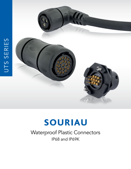


プラスチック製 IP68/69K防水コネクタ
UTSシリーズは、1/3回転バイヨネットカップリングを備えた防水丸形プラスチックコネクタで、クリック音による嵌合確認により、迅速で正しい接続を保証します。
IECおよびUL規格に準拠するよう開発されたTrim Trioは設置者および利用者の安全条件を保証します。
屋外用に最適なコネクタです。
防湿性と紫外線耐性(IP68/69Kシーリングレベル)を備えるUTSシリーズは、屋外で長時間利用することができ、メンテナンスの必要性を低減します。UTS ハイシールタイプでは、嵌合・非嵌合状態であっても、業界最高水準の防水性IP68/IP69Kレベルを維持します。
UTSシリーズは、同じコネクタ内に信号と電源、または銅線と光ファイバーを結合する幅広い種類のレイアウトを提供します。
UTSシリーズはTrim Trioコンタクトを使用し、UTGやUTOシリーズと完全に互換します。その結果、工具やパネルカットアウトを変更することなく、1つのシリーズから別のシリーズに変更することができます。追加費用なしで、製品を簡単かつ迅速にアップグレードできます!
UTSシリーズについてご質問がありますか?または、お見積りが必要ですか?弊社の技術チームおよび営業チームがサポートいたします。
お気軽に service_jpn-itd@eaton.com までお問合せください。
関連メディア
このカタログについて
| ドキュメント名 | 防塵・防水フルプラスチックコネクタ UTSシリーズ |
|---|---|
| ドキュメント種別 | 製品カタログ |
| ファイルサイズ | 35.4Mb |
| 登録カテゴリ | |
| 取り扱い企業 | スリオジャパン株式会社 (この企業の取り扱いカタログ一覧) |
この企業の関連カタログ


このカタログの内容
Page1
Waterproof Plastic Connectors
IP68 and IP69K
UTS SERIES
Page3
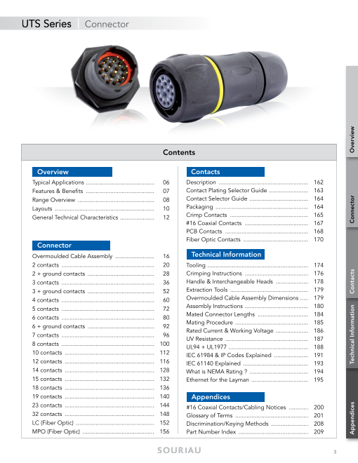
UTS Series | Connector
Contents
Overview Contacts
Typical Applications .......................................... 06 Description ....................................................... 162
Features & Benefits .......................................... 07 Contact Plating Selector Guide ........................ 163
Range Overview ............................................... 08 Contact Selector Guide .................................... 164
Layouts ............................................................. 10 Packaging ......................................................... 164
General Technical Characteristics ..................... 12 Crimp Contacts ................................................ 165
#16 Coaxial Contacts ....................................... 167
PCB Contacts ................................................... 168
Fiber Optic Contacts ........................................ 170
Connector
Overmoulded Cable Assembly ........................ 16 Technical Information
2 contacts ......................................................... 20 Tooling .............................................................. 174
2 + ground contacts ......................................... 28 Crimping Instructions ....................................... 176
3 contacts ......................................................... 36 Handle & Interchangeable Heads .................... 178
3 + ground contacts ......................................... 52 Extraction Tools ................................................ 179
4 contacts ......................................................... 60 Overmoulded Cable Assembly Dimensions ..... 179
5 contacts ......................................................... 72 Assembly Instructions ....................................... 180
6 contacts ......................................................... 80 Mated Connector Lengths ............................... 184
Mating Procedure ............................................. 185
6 + ground contacts ......................................... 92
Rated Current & Working Voltage .................... 186
7 contacts ......................................................... 96
UV Resistance ................................................... 187
8 contacts ......................................................... 100 UL94 + UL1977 ................................................. 188
10 contacts ....................................................... 112 IEC 61984 & IP Codes Explained ..................... 191
12 contacts ....................................................... 116 IEC 61140 Explained ........................................ 193
14 contacts ....................................................... 128 What is NEMA Rating ? .................................... 194
15 contacts ....................................................... 132 Ethernet for the Layman ................................... 195
18 contacts ....................................................... 136
19 contacts ....................................................... 140 Appendices
23 contacts ....................................................... 144 #16 Coaxial Contacts/Cabling Notices ............ 200
32 contacts ....................................................... 148 Glossary of Terms ............................................. 201
LC (Fiber Optic) ................................................ 152 Discrimination/Keying Methods ....................... 208
MPO (Fiber Optic) ............................................ 156 Part Number Index ........................................... 209
3
Appendices Technical Information Contacts Connector Overview
Page4
© 2014 SOURIAU - SOURIAU is a registered trademark
UTS SERIES
Page5
UTS Series
Overview
Typical Applications ................................................................................................ 06
Features & Benefits ................................................................................................ 07
Range Overview .................................................................................................... 08
Layouts ................................................................................................................... 10
General Technical Characteristics ........................................................................... 12
5
Page6
UTS Series | Overview
Typical Applications
Energy - Power Off-Road Building Automation & Control
Instrumentation - Measurement Rail
Stage - Light
6
© cachoudesign / Fotolia © krungchingpixs / Fotolia © Vibe Images / Fotolia
© Pinosub / Fotolia © Sergey Milovidov / Fotolia
© Volodymyr Kyrylyuk / Fotolia
Page7
UTS Series | Overview
Features & Benefits
IP68/69k Dynamic Mated & Unmated
WATER Ideal for outdoor and indoor dynamic applications requiring
continuous underwater immersion, routine pressure washing
PROOF and dust protection.
No Degradation Over Time
UV No mechanical deterioration or important variation in colour after
5 years of exposure in natural environment (equivalent exposure
RESISTANT to sun and moisture as per ISO4892) and F1 rated per UL 746C.
qualified & Certified
UL/IEC In accordance with:
- UL 1977 - Certificate ECBT2, File number: E169916
COMPLIANT - CSA C22.2 n°182.3 - Certificate ECBT8, File number: E169916.
1/3 Bayonet Coupling
qUICk With only 1/3 twist of the bayonet coupling system, connectors are
mated with audible "click" and tactile feel to confirm proper mating.
MATINg This mating feature eliminates connection uncertainty and reduces
time and labor during installation.
Mixed Power & Signal Contacts
COST Power supply and signal transmission can be combined in
a unique interconnect solution to reduce system complexity
SAVINgS and minimize component installation cost.
7
Overview
Page8
UTS Series | Overview
Range
UTS Series UTS Standard
Cable Sealed Single Wire
Sealed
Sealed: IP68/69K dynamic Corrosion-proof
UV resistant Plastic housing
UL/IEC compliant
UTS Backshells Contacts Supplied Separately
Cable Sealing
Choice of Crimp Contacts
• Machined
• Stamped and Formed
• Coaxial Plug
PCB Contacts
Double Sealing Fiber Optic
(Wires + Cable)
Contacts Loaded
Screw Termination
grommet Contacts Loaded
Handsolder
Single Wire
Sealed
UTS Sealed Unmated
Flexible conduit
adaptators
Sealed Unmated: IP68/69K dynamic
MIL-C-26482 compatible
Contact us for more information UV resistant
UL/IEC compliant Corrosion-proof
Plastic housing
Overmoulded Cable Assembly
8
Page9
UTS Series | Overview
Overview
UTS Standard Receptacle
Contacts Supplied Separately
UTS Backshells
Square Flange Choice of Crimp Contacts
• Machined
• Stamped and Formed Cable Sealing
• Coaxial
PCB Contacts
Fiber Optic
Threaded Receptacle
Contacts Supplied Separately Double Sealing
(Wires + Cable)
Choice of Crimp Contacts
• Machined
• Stamped and Formed
• Coaxial grommet
In-line PCB Contacts
Fiber Optic Single Wire
Sealed
Contacts Loaded
Jam Nut Flexible conduit
Screw Termination adaptators
PCB
UTS Sealed Unmated
Receptacle
Contact us for more information
UTS PCB Contacts
Stand-offs to allow Metal hold down clips
Contacts Loaded cleaning after - to lock the connector easily on
soldering the PCB and to release stress
on solder joints
Jam Nut Handsolder - suitable for soldering in a
metallic hole
PCB
Pre-assembled PCB contacts
- machined or stamped versions
available
Square Flange - different solder tails lengths
Low profile housing to limit possible
space between panel and PCB - different plating options
9
Overview
Page10
UTS Series | Overview
Layouts (Electrical parameter according to IEC)
Shell Size Contact #16 (Ø 1.6mm) Contact #20 (Ø 1.0mm) Contact #8 (Ø 3.6mm) Hybrid & others
8E2/8D2(1) 8E3/8D3(1)
7A 32V 7A 32V
2 contacts 3 contacts
Page 20 Page 36
8E3A/8D3A(1) 8E98/8D98(1)
7A 50V 7A 50V
8 3 contacts 3 contacts
Page 40 Page 40
8E33/8D33(1) 8E4/8D4(1)*
7A 50V 7A 32V
3 contacts 4 contacts
Page 44 Page 60
106* 102W2 103W3
25A 150V 5A 32V
103 104(3) 10E6(1)/10D6
4 contacts 6 contacts
16A 300V 13A 150V 7A 32V
2xØ2.4 (#12) 3xØ1.6 (#16)
2+ground 4 contacts 6 contacts 2xØ1.0 (#20) 3xØ1.0 (#20)
10 Page 28 Page 68 Page 84 Page 64 Page 80
10E98/10D98 10E7(1)/10D7
7A 50V 7A 50V
6 contacts 7 contacts
Page 88 Page 96
1210*
12E2/12D2 12E3/12D3 12E10/12D10
16A 150V 16A 150V 6A 50V
2 contacts 3 contacts 10 contacts
11 1
1
1
22 2 1
55 5 44 4
12 Page 24 Page 48 Page 112 1 2 5 4
2 5 4
2
124 5 4
1 2 5 4 33 3
12E4/12D4 28(1) (3) 12E8/12D8 12E14/12D14 3
10A 80V 6A 32V 5A 32V 3
16A 300V 3
8 contacts 8 contacts 14 contacts
3+ground 3
Page 52 Page 100 Page 104 Page 128
1: M12, M16 and M20 threaded receptacle available 2: NPT available 3: Discrete wire grommet option * Ethernet compatible: see pages 195 & 196
10
1 1
1
2 2 5 5 4 4
2 5 4
3 3
3
Page11
UTS Series | Overview
Contacts #20: Contacts #16: Contacts #12: Contacts #8:
from AWG 26 to 18 from AWG 30 to 14 from AWG 22 to 12 from AWG 16 to 8
0.13 to 0.93 mm² 0.05 to 2.5 mm² 0.13 to 4 mm² 1.5 to 10 mm²
Shell Size Contact #16 (Ø 1.6mm) Contact #20 (Ø 1.0mm) Contact #8 (Ø 3.6mm) Mixed Power
147(3) 14E18/14D18 142g1(2) 148
14E5/14D5 14E7/14D7 5A 50V 40A 300V 17A 230V
16A 150V 16A 300V 18 contacts 2+ground 8 contacts
4xØ1.6 (#16)+4xØ2.4 (#12)
5 contacts 6+ground
Page 136 Page 32 Page 108
Page 72 Page 92 14E12/14D12
4A 50V
1412(3) 1492(3) 1419 12 contacts
10A 63V 10A 63V 14E19/14D19 4xØ1.6 (#16)+8xØ1.0 (#20)
12 contacts 12 contacts 5A 32V
14 19 contacts
Page 120
Page 116 Page 124 14E15/14D15
Page 140 4A 50V
15 contacts
1xØ1.6 (#16)+14xØ1.0 (#20)
Page 132
18X2M3(2)
1823 18E32/18D32 183g1(2) 32A 300V
9A 63V 4A 32V 32A 300V 5 contacts
23 contacts 32 contacts 3+ground 3xØ1.6 (#16)+2xØ3.6 (#8)
1
1
2 5 4
1
2 5 4
2 3
5 4
3
Page 144 Page 148 Page 56 Pag3e 76
LC
18
Page 152
MPO
Page 156
XXXXXX blue highlighted items: UTS Sealed in Unmated Condition
11
Overview
Page12
UTS Series | Overview
General Technical Characteristics
Materials Environmental Electrical
• Body connector + Backshell: Thermoplastic • Operating temperature: • In accordance with:
from -40°C to +105°C - UL 1977: Certificat ECBT2
• Insert: 40/100/21 per NFF 61-030 File number: E169916
- UTS Standard, UTS Single Wire Sealed, - CSA C22.2 n°182.3: Certificat ECBT8
UTS Screw Termination Contacts: • Flammability rating: File number: E169916
Thermoplastic - UL94 V-0 (all UTS except the Sealed
- UTS Sealed Unmated Handsolder & Unmated version) see page 180
UTS Sealed Unmated with PC Tails - UL94 HB (UTS Sealed Unmated version
Contacts: Elastomer only) see page 180
- I2F3 according to NFF 16101 & NFF 16102
• Nut: Metal • Also see pages 10 & 11
• Salt spray:
• Contacts: See page 161 per EIA-026A ≥500 hours
• Halogen free • UV resistant:
No mechanical degradation or important
• RoHS compliant & conforms to the Chinese variation of colour after 5 years of exposure
standard SJ/T1166-2006 in natural environment (equivalence exposure Mechanical
(Chinese RoHS equivalent) to sun and moisture as per ISO 4892) and
F1 rated per UL 746C • Durability:
250 matings & unmatings per MIL-C-26482
• Sealing:
- UTS Standard: IP68/IP69K dynamic (mated) • Vibration resistance (all UTS versions
- UTS Sealed Unmated version: except UTS Screw Termination contacts):
IP68/IP69K dynamic (unmated) Sinusoidal vibrations per IEC 60512-4 - from
- UTS Single Wire Sealed: IP67/69K (up to 10 to 2000 Hz
IP68 with double sealing backshell)
- UTS Screw Termination Contacts: • Thermal shock:
IP68/IP69K dynamic (mated) 5 cycles 30 min. from -40°C to 105°C per
Note: IP68=10 m underwater during 1 week MIL-STD-1344 method 1003
• Fluid resistance:
- Gas and Oil
- Mineral oil
- Acid bath
- Basic bath
12
Page13
UTS Series | Overview
13
Overview
Page14
© 2014 SOURIAU - SOURIAU is a registered trademark
UTS SERIES
Page15
UTS Series
Connector
Overmoulded Cable Assembly .............................................................................. 16
2 contacts
8E2/8D2: 7A 32V ................................................................. 20
12E2/12D2: 16A 150V ................................................................. 24
2 contacts + ground
103: 16A 300V ................................................................. 28
142G1: 40A 300V ................................................................. 32
3 contacts
8E3/8D3: 7A 32V ................................................................. 36
8E3A/8E98 - 8D3A/8D98: 7A 50V ................................................................. 40
8E33/8D33: 7A 50V ................................................................. 44
12E3/12D3: 16A 150V ................................................................. 48
3 contacts + ground
124 - 12E4/12D4: 16A 300V ................................................................. 52
183G1: 32A 300V ................................................................. 56
4 contacts
8E4/8D4*: 7A 32V ................................................................. 60
102W2: 25A 150V ................................................................. 64
104: 13A 150V ................................................................. 68
5 contacts
14E5/14D5: 16A 150V ................................................................. 72
18X2M3: 32A 300V ................................................................. 76
6 contacts
103W3: 5A 32V ................................................................. 80
106* - 10E6/10D6: 7A 32V ................................................................. 84
10E98/10D98: 7A 50V ................................................................. 88
6 contacts + ground
147 - 14E7/14D7: 16A 300V ................................................................. 92
7 contacts
10E7/10D7: 7A 50V ................................................................. 96
8 contacts
128: 10A 80V ................................................................. 100
12E8/12D8: 6A 32V ................................................................. 104
148: 17A 230V ................................................................. 108
10 contacts
1210* - 12E10/12D10: 6A 50V ................................................................. 112
12 contacts
1412: 10A 63V ................................................................. 116
14E12/14D12: 4A 50V ................................................................. 120
1492: 10A 63V ................................................................. 124
14 contacts
12E14/12D14: 5A 32V ................................................................. 128
15 contacts
14E15/14D15: 4A 50V ................................................................. 132
18 contacts
14E18/14D18: 5A 50V ................................................................. 136
19 contacts
1419 - 14E19/14D19: 5A 32V ................................................................. 140
23 contacts
1823: 9A 63V ................................................................. 144
32 contacts
1832 - 18E32: 4A 32V ................................................................. 148
LC .......................................................................................................................... 152
MPO ...................................................................................................................... 156
Electrical parameters according to IEC * Ethernet compatible see pages 195 & 196
15
Page16
UTS Series | Connector
Overmoulded Cable Assembly
SOURIAU has provided connectors in various applications for more than 90 years and used in the most extreme environments. Conscious
about the difficulty to finding a quick and a reliable harness manufacturer, we began in-house cable assembly production. It allows
customers to reduce the number of suppliers, and to take advantage of the "best in class" quality of the SOURIAU group. Overmoulding
is a process that further enhances the sealing properties of the UTS range, especially over many years of use. Overmoulding provides
the opportunity to change the cable exit from straight to 90 degrees and avoid stress on the cable terminated to the connector. Also, as
the wires are encapsulated inside the molding, a barrier is created which prevents any liquid from entering the equipment through the
connector if the cable jacket is breached.
How to choose the outer jacket material
Please consult us
TPE
Static installation SILICON
Static installation
OUTDOOR FEP
Static installation
(black outer jacket)
PUR PTFE
Static installation
Static or dynamic installation
INDOOR
PVC
Static or dynamic installation
-40°C +80°C Ambient temperature
16
Chemical aggression Cleaner,
Wet Immersed chlorine
UV resistance
Page17
UTS Series | Connector
Overmoulding Description
Thermoplastic or
elastomer insert Compound Cable outer sheath
PVC or PUR
O-ring Overmoulding adapter overmoulding
Connector with cable gland backshell
If cable jacket is breached...
gOOD
...water ingress unhampered, leading to damage.
Overmoulded connector
If cable jacket is breached...
BEST
...prevents water ingress via capillary action.
17
Connector
Page18
UTS Series | Connector
UTS Waterproof Plastic Overmould
HAUTS Standard
Offering Description
Cable
• PVC outer sheath (grey color)
• Wire section 1.5 mm² for #16 contact
• Wire section 0.5 mm² for #20 contact
• 300V
• Unshielded
• Flammability rating IEC (UL1581 Sec.1160)
• Operating temperature: -40°C +70°C
Overmoulding Specifications
PLATINg SALT SPRAY TEMPERATURE* WATERPROOF* MECHANICAL
No plating 500 H -40°C up to + 105°C IP68/IP69K dynamic (mated) 250 matings/unmatings
* With appropriate cable and overmoulding
Example of Customized Cable Assemblies
Overmoulding on Curly Cable Overmoulding with Double Ends Harness for PCB Connection
To define your customized cable assembly, please consult our technical services.
18
Page19
UTS Series | Connector
Cable Information
Range of temperature: Occasional flexing: -5°C up to +70°C
Fixed installation: -40°C up to +80°C
Rated voltage: U0/U: 300/500V
Wire section : Layouts with #16 contact: wire section 1.5 mm²
Layouts with #20 contact: wire section 0.5 mm²
Harmonized reference: H05 VV - F XX
Standardisation of European Cable - DIN VDE 0281/DIN VDE 0282/DIN VDE 0292
Harmonized wire coding system
1 2 3 4 5 6 7 8 9
1. 2. 3. 4. 5. 6. 7. 8. 9.
Basic type Working Insulating Sheath- Special Conductor Number of Protective Conductor
voltage cladding features types conductors conductor cross-
material sectional
H: 03: V: V: H: U: X: Area specified
Harmonized 300/300V PVC PVC Ribbon cable, Single wire Without in mm2
Type separable protective
conductor
A: 05: R: R: H2: Ribbon R: G:
National Type 300/500V Rubber Rubber cable Multi-wire With
non-separable protective
conductor
07: S: N: K:
450/750V Silicone Cloroprene Fine wire
Rubber Rubber (permanently
installed)
J: F:
Glass-filament Fine wire
braiding (flexible)
T: H:
Textile Super fine wire
braiding
Y:
Tinsel strand
Example: Harmonized type, 300/500V, PVC insulating, PVC sheath- cladding, Fine wire, 3x1.5 cross-sectional: H05VVF3x1.5
19
Connector
Page20
UTS Series | Connector
8E2/8D2 (Shell size 8, 2x#20)
Layout
OR OR OR
WITH
Connector Part Numbers
Part number
Contact type Connector type Backshell
Male insert Female insert
Square flange
receptacle Without (Fig.1) UTS08E2P UTS08E2S
Handsolder Without (Fig.7) UTS68E2P UTS68E2S
electrical contacts Plug
loaded Cable gland (Fig.8) UTS6JC8E2P UTS6JC8E2S
see page 23 Jam nut
receptacle Without (Fig.4) UTS78E2P UTS78E2S
M12 threaded receptacle Without (Fig.3) UTS78E2PM12 UTS78E2SM12
Square flange
Without (Fig.2)
receptacle UTS08D2P UTS08D2S
Jam nut receptacle
PCB with stand off and Without (Fig.6) UTS78D2P32 UTS78D2S32
contacts loaded with hold down clips
see page 23 Jam nut receptacle
with stand off and Without (Fig.5) UTS78D2P UTS78D2S
without hold down clip
M12 threaded receptacle Without (Fig.3) UTS78D2PM12 UTS78D2SM12
Possibilities of discrimination/keying methods see page 208 Sealed unmated
Overmoulded Cable Assembly Part Numbers
Wire size Harmonized cable Part number (length: 1m.)*
Overmoulding type Connector type
(mm²) part number (1)
Male plug Female plug
Straight ending Plug 0.5 H05 VV - F 2x0.5 HAUTS0V8E2PST100 HAUTS0V8E2SST100
Right angle ending Plug 0.5 H05 VV - F 2x0.5 HAUTS0V8E2PRA100 HAUTS0V8E2SRA100
(1) Other cable available on demand * Other lengths available on demand
20