このカタログをダウンロードして
すべてを見る


ご希望の型式をお探しください
このカタログについて
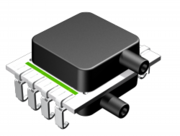
| ドキュメント名 | デジタル出力微差圧センサ DLVR |
|---|---|
| ドキュメント種別 | 製品カタログ |
| ファイルサイズ | 3.2Mb |
| 登録カテゴリ | |
| 取り扱い企業 | オールセンサーズアジアパシフィック株式会社 (この企業の取り扱いカタログ一覧) |
この企業の関連カタログ


このカタログ(デジタル出力微差圧センサ DLVR)の内容
Page 1:a16035VineyardBlvd.MorganHill,CA95037p4082254314f4082252079ewww.allsensors.comallsensorsAll Sensors DS-0300 Rev CThe DLVR Series Mini Digital Output Sensor is based on All Sensors’CoBeam2 TMTechnology. This reduces package stresssusceptibility, resulting in improved overall long term stability. The technology also vastly improves position sensitivitycompared to single die devices.The supply voltage options ease integration of the sensors into a wide range of process control and measurement sys-tems, allowing direct connection to serial communications channels. For battery-powered systems, the sensors can entervery low-power modes between readings to minimize load on the power supply.These calibrated and compensated sensors provide accurate, stable output over a wide temperature range. This seriesis intended for use with non-corrosive, non-ionic working fluids such as air, dry gases and the like. A protective parylenecoating is optionally available for moisture/harsh media protection.• 0.5 to 60 inH2O Pressure Ranges• 3.3V Supply Voltage Standard / 5V Option• I2C Standard Interface / SPI Interface Option• Better than 1.0% Accuracy Over Temperature Typical• Medical Breathing• Environmental Controls• HVAC• Industrial Controls• Portable/Hand-Held EquipmentGeneral DescriptionApplicationsFeaturesDLVR Series Low Voltage Digital Pressure SensorsDevice Operating Range Proof Pressure Burst Pressure Nominal SpanDLVR-F50D ±0.5 inH2O 100 inH2O 300 inH2O ±6,553 countsDLVR-L01D ±1 inH2O 100 inH2O 300 inH2O ±6,553 countsDLVR-L02D ±2 inH2O 100 inH2O 300 inH2O ±6,553 countsDLVR-L05D ±5 inH2O 200 inH2O 300 inH2O ±6,553 countsDLVR-L10D ±10 inH2O 200 inH2O 300 inH2O ±6,553 countsDLVR-L20D ±20 inH2O 200 inH2O 500 inH2O ±6,553 countsDLVR-L30D ±30 inH2O 200 inH2O 500 inH2O ±6,553 countsDLVR-L60D ±60 inH2O 200 inH2O 800 inH2O ±6,553 countsDLVR-L01G 0 to 1 inH2O 100 inH2O 300 inH2O 13,107 countsDLVR-L02G 0 to 2 inH2O 100 inH2O 300 inH2O 13,107 countsDLVR-L05G 0 to 5 inH2O 200 inH2O 300 inH2O 13,107 countsDLVR-L10G 0 to 10 inH2O 200 inH2O 300 inH2O 13,107 countsDLVR-L20G 0 to 20 inH2O 200 inH2O 500 inH2O 13,107 countsDLVR-L30G 0 to 30 inH2O 200 inH2O 500 inH2O 13,107 countsDLVR-L60G 0 to 60 inH2O 200 inH2O 800 inH2O 13,107 countsPressure Sensor Maximum Ratings Environmental SpecificationsSupply Voltage (Vs) 6 VdcCommon Mode Pressure 10 psigLead Temperature (soldering 2-4 sec.) 270 °CTemperature RangesCompensated: Commercial 0°C to 70°C Industrial -20°C to 85°C Operating -25°C to 85 °C Storage -40°C to 125 °CHumidity Limits (non condensing) 0 to 95% RHStandard Pressure Ranges Equivalent CircuitPage 1I2CVsGndSCLSDAINTSPIOptionVsGndSCLKMISOSSnsors.cominalInRedRwww.allsensors.comOriginalInRedRwww.allsensors.comOriginalInRedRwwww.allsensors.comOriginalInRedRwww.allsensors.comOriginalInRedRmInRedRwww.allsensors.comOriginalInRedRwww.allsensors.comOriginalInRedRwww.allsenOrigiwww.allsensors.comOriginalInRedRwww.allsensors.comOriginalInRedR
Page 2:DLVR Series Low Voltage Digital Pressure SensorsParameter Min Typ Max Units NotesOutput Span 1LxxD, FxxD - ±6,553 - Dec countLxxG - 13,107 - Dec countOffset Output @ Zero Diff. Pressure -LxxD, FxxD - 8,192 - Dec countLxxG - 1,638 - Dec countTotal Error Band 2F50D - ±2.0 ±2.5 %SpanL01x, L02x - ±1.5 ±2.0 %SpanL05x, L10x, L20x, L30x, L60x - ±1.0 ±1.5 %SpanSpan Temperature Shift 3F50D, L01x, L02x - ±0.5 - %FSSL05x, L10x, L20x, L30x, L60x - ±0.2 - %FSSOffset Temperature Shift 3F50D, L01x, L02x - ±0.5 - %FSSL05x, L10x, L20x, L30x, L60x - ±0.2 - %FSSOffset Warm-up Shift 4F50D, L01x, L02x - ±0.25 - %FSSL05x, L10x, L20x, L30x, L60x - ±0.15 - %FSSOffset Position Sensitivity (±1g) -F50D, L01x, L02x - ±0.10 - %FSSL05x, L10x, L20x, L30x, L60x - ±0.05 - %FSSOffset Long Term Drift (One Year) -F50D, L01x, L02x - ±0.25 - %FSSL05x, L10x, L20x, L30x, L60x - ±0.15 - %FSSLinearity, Hysteresis Error 6F50D - ±0.30 - %FSSLxxD - ±0.25 - %FSSLxxG - ±0.10 - %FSSResponse Delay 5Sleep - Wake Pressure - 0.40 0.50 msSleep - Wake All - 1.10 1.40 msUpdate Rate 5Fast - 0.40 1.0 msNoise Reduced - 1.30 3.1 msLow Power - 6.5 9.5 msDigital Resolution -Output Resolution - 14 - bitNo Missing Codes 12 13 - bitTemperature Output 7Resolution - 11 - bitOverall Accuracy - 2 - °CCurrent Requirement (3.3V Option) 5Fast - 3.5 4.3 mANoise Reduced - 3.6 4.5 mALow Power - 0.72 0.90 mASleep (Idle) - 0.5 5.0 uACurrent Requirement (5.0 Option) 5Fast - 5.0 6.0 mANoise Reduced - 5.2 6.2 mALow Power - 1.1 1.3 mASleep (Idle) - 0.5 5.0 uAPerformance Characteristics for DLVR Series - Commercial and Industrial Temperature RangeAll parameters are measured at 3.3V ±5% or 5.0V ±5% (depending on selected voltage option) excitation and room temperature unless otherwise specified.Pressure measurements are with positive pressure applied to PORT B.See following page for performance characteristics table notesPage 2nsors.cominalInRedRwww.allsensors.comOriginalInRedRwww.allsensors.comOriginalInRedRwwww.allsensors.comOriginalInRedRwww.allsensors.comOriginalInRedRmInRedRwww.allsensors.comOriginalInRedRwww.allsensors.comOriginalInRedRwww.allsenOrigiwww.allsensors.comOriginalInRedRwww.allsensors.comOriginalInRedR
Page 3:a16035VineyardBlvd.MorganHill,CA95037p4082254314f4082252079ewww.allsensors.comallsensorsAll Sensors DS-0300 Rev CPage 3Specification Notesnote 1: THE SPAN IS THE ALGEBRAIC DIFFERENCE BETWEEN FULL SCALE DECIMAL COUNTS AND THE OFFSET DECIMAL COUNTS.note 2: TOTAL ERROR BAND COMPRISES OF OFFSET AND SPAN TEMPERATURE AND CALIBRATION ERRORS, LINEARITY AND PRESSURE HYSTERISIS ERRORS, OFFSET WARM-UP SHIFT,OFFSET POSITION SENSITIVITY AND LONG TERM OFFSET DRIFT ERRORS.note 3: SHIFT IS RELATIVE TO 25C.note 4: SHIFT IS WITHIN THE FIRST HOUR OF EXCITATION APPLIED TO THE DEVICE.note 5: PARAMETER IS CHARACTERIZED AND NOT 100% TESTED.note 6: MEASURED AT ONE-HALF FULL SCALE RATED PRESSURE USING BEST STARIGHT LINE CURVE FIT.note 7: TEMPERATURE OUTPUT CONVERSION FUNCTION:DLVR Transfer Functions NOTE 1: Pressure Output Transfer Function: ������������2�� � ��2� � �������� � �����2��� � �������2�� Where, ������� Is the sensor 14 bit digital output. ����� Is the specified digital offset (gage = 1,638 and differential = 8,192) �������2�� Is the sensor Full Scale Span in inH2O (gage = Full Scale Pressure, differential = 2 x Full Scale Pressure) NOTE 2: Temperature Output Transfer Function: �������������� � ������� � �2002�� � �� � �0 Parameter Symbol Min Typ Max Units NotesInput High Level - 80.0 - 100 % of Vs 5Input Low Level - 0 - 20.0 % of Vs 5Output Low Level - - - 10.0 % of Vs 5I2C Pull-up Resistor - 1000 - - ٠5I2C Load Capacitance on SDA, @ 400 kHz CSDA --200pF 5I2C Input Capacitance (each pin) CI2C_IN --10.0pF 5I2C / SPI Electrical Parameters for DLVR Seriesnsors.cominalInRedRwww.allsensors.comOriginalInRedRwww.allsensors.comOriginalInRedRwwww.allsensors.comOriginalInRedRwww.allsensors.comOriginalInRedRmInRedRwww.allsensors.comOriginalInRedRwww.allsensors.comOriginalInRedRwww.allsenOrigiwww.allsensors.comOriginalInRedRwww.allsensors.comOriginalInRedR
Page 4:DLVR Series Low Voltage Digital Pressure SensorsDevice OptionsThe following is a list of factory programmable options. Consult the factory to learn more about the options.InterfaceI2C and SPI interfaces are available. NOTE: SPI interface is only available with eight (8) lead packages.Supply VoltageDevices are characterized at either 3.3V or 5.0V depending on the options selected. It is suggested to selectthe option that most closely matches the application supply voltage for best possible performance.Speed/PowerThere are four options of Speed/Power. These are Fast(F), Noise Reduced(N), Low Power(L) and Sleep mode(S).Fast Mode(F) Is the fastest operating mode where the device operates with continuous sampling at thefastest internal speed.Noise Reduced(N): Also operates with continuous samples however the ADC is set for over samplingfor noise reduction. The conversion times are resultantly longer than the Fast(F) mode however, there isapproximately 1/2 bit reduction in noise.Low Power(L): Is similar to the Fast(F) mode with exception that the device uses an internal timer todelay between pressure conversions. The internal timer time-out triggers the next conversion cycle. Theupdate rate is commensurately lower for this mode as a result.Sleep(S): Is similar to the Low Power(L) mode however the trigger to initiate a sample comes from theuser instead of an internal timer. This is ideal for very low update rate applications that requirelowpower usage. It is also ideal for synchronizing the data conversions with the host microprocessor.CoatingParylene Coating: Parylene coating provides a moisture barrier and protection form some harsh media. Con-sult factory for applicability of Parylene for the target application and sensor type.Page 4nsors.cominalInRedRwww.allsensors.comOriginalInRedRwww.allsensors.comOriginalInRedRwwww.allsensors.comOriginalInRedRwww.allsensors.comOriginalInRedRmInRedRwww.allsensors.comOriginalInRedRwww.allsensors.comOriginalInRedRwww.allsenOrigiwww.allsensors.comOriginalInRedRwww.allsensors.comOriginalInRedR
Page 5:a16035VineyardBlvd.MorganHill,CA95037p4082254314f4082252079ewww.allsensors.comallsensorsAll Sensors DS-0300 Rev COperation OverviewThe DLVR is a digital sensor with a signal path that includes a sensing element, a 14 bit analog to digital converter, a DSP andan IO block that supports either an I2C or SPI interface (see Figure 1 below). The sensor also includes an internal temperaturereference and associated control logic to support the configured operating mode. The sensing element is powered downwhile not being sampled to conserve power. Since there is a single ADC, there is also a multiplexer at the front end of theADC that selects the signal source for the ADC.oTZeroVsGndI2C/SPIrawP/rawTPressureWakeTemperatureSample OverSampleEnableSensorP/T/ZSelect210ADDSPControlLogicI/OFigure 1 - DLVR Essential ModelThe ADC performs conversions on the raw sensor signal (P), the temperature reference (T) and a zero reference (Z) during anADC zero cycle. It also has an oversampling mode for a noise reduced output. A conversion cycle that is mesuring pressureis called a Normal cycle. A cycle where either a temperature measurement or zeroing is being performed is called a Specialcycle.The DSP receives the converted pressure and temperature information and applies a multi-order transfer function tocompensate the pressure output. This transfer function includes compensation for span, offset, temperature effects of span,temperature effects of offset and second order temperautre effects of both span and offset. There is also linearity compensa-tion for gage devices and front to back linearity compensation for differential devices.There are two effective operating modes of the sensor 1) Free Running and 2) Triggered. The control logic performs thesynchronization of the internal functions according the factory programmed Power/Speed option (see Table 1). The ControlLogic also determines the Delay between ADC samples, the regularity of the Special cycles and whether or not the ADC per-forms the Over Sampling. Refer to Figure 2 for the communication model associated with the operating modes listed below.Free Running Mode: In the free running mode, conversion cycles are initiated internally at regular intervals. There arethree options available that operate in the Free Running mode (F, N and L). Two of these (F and N) run continuously whilethe third option (L) has an approximate 6 ms delay between conversion cycles. All three options have Special cyclesinserted at regular intervals to accomplish the ADC zeroing and temperature measurements. Two of the options utilizeoversampling. Refer to Table 1 for specific option controls.Triggered Mode: In the Triggered Mode, a conversion cycle is initiated by the user (or host uP). There are two availabemethods to wake the sensor from sleep mode. The first method (Wake All) is to wake the sensor and perform all threemeasurement cycles (Z, T and P). This provides completely fresh data from the sensor. The second method (Wake P) isto wake the sensor from sleep and only perform the pressure measurement (P).When using this second method, it is upto the user to interleave Wake All commands at regular intervals to ensure there is sufficiently up to date temperatureinformation. Also, the Wake Pressure method is only available from the I2C interface (not available using a SPI interface).Page 5nsors.cominalInRedRwww.allsensors.comOriginalInRedRwww.allsensors.comOriginalInRedRwwww.allsensors.comOriginalInRedRwww.allsensors.comOriginalInRedRmInRedRwww.allsensors.comOriginalInRedRwww.allsensors.comOriginalInRedRwww.allsenOrigiwww.allsensors.comOriginalInRedRwww.allsensors.comOriginalInRedR
Page 6:DLVR Series Low Voltage Digital Pressure SensorsTable 1 - DLVR Control Logic DetailOperation Overview (Cont’d)Figure 2 - DLVR Communication ModelPower/SpeedOptionPower/SpeedDescriptionOperatingModeOverSampleDelayBetweenSamplesNormalADCCyclesSpecialADCCyclesSpecialADC CycleIntervalF Fast No No 1 (P) 1 (Z or T) 255N Noise Reduced Yes No 1 (P) 1 (Z or T) 255L Low Power Yes Yes 1 (P) 1 (Z or T) 31Sleep(1)(Wake Pressure) No User Defined 1 (P) n/a NeverSleep (Wake All) No User Defined 1 (P) 2 (Z T) AlwaysNote 1) Wake from sleep with pressure only reading is not available with SPI interface (I2C only).Control LogicSFreeRunningTriggeredFree Running Mode [(F)ast, (N)oise Reduced and (L)ow Power Option]Cycle TypeInternal Operation DSP Delay ADC (P) DSP Delay ADC (P) DSP Delay ADC (P) ADC (T or Z) DSP Delay ADC (P)New Data AvailableNote 1: See Table 1 for frequency of Special CyclesNormal Cycle Normal Cycle Special Cycle (1)Triggered Mode - Wake All [(S)leep Option]orSPI (SS) Read DataInternal Operation ADC (Z) ADC (T) ADC (P) DSP ADC (Z) ADC (T) ADC (P) DSP SleepNew Data AvailableWake All Wake AllSleepI2C Read DataSleepTriggered Mode - Wake Pressure [(S)leep Option]Internal Operation ADC (P) DSP ADC (P) DSP SleepNew Data AvailableI2C Wake P. Read Data Wake P.Sleep SleepPage 6nsors.cominalInRedRwww.allsensors.comOriginalInRedRwww.allsensors.comOriginalInRedRwwww.allsensors.comOriginalInRedRwww.allsensors.comOriginalInRedRmInRedRwww.allsensors.comOriginalInRedRwww.allsensors.comOriginalInRedRwww.allsenOrigiwww.allsensors.comOriginalInRedRwww.allsensors.comOriginalInRedR
Page 7:a16035VineyardBlvd.MorganHill,CA95037p4082254314f4082252079ewww.allsensors.comallsensorsAll Sensors DS-0300 Rev CDigital Interface Data FormatFor either type of digital interface, the format of data returned from the sensor is the same. The first 16 bits consist ofthe 2 Status bits followed by the 14-bit the pressure value. The third byte provides the 8 most significant bits of the mea-sured temperature; the fourth byte provides the 3 least significant bits of temperature, followed by 5 bits of undefinedfiller data. With either interface, the host may terminate the transfer after receiving the first two bytes of data from thesensor, or following the third byte (if just the most-significant 8 bits of temperature are needed). Refer to Table 2 for theoverall data format of the sensor. Table 3 shows the Status Bit definition.Bit Definitions:Status (S): Normal/command / busy / diagnosticPressure (P): Digital pressure readingTemperature (T): Compensated temperature readingTable 2 - Output Data FormatTable 3- Status Bit DefinitionsI2C InterfaceI2C Communications OverviewThe I2C interface uses a set of signal sequences for communication. The following is a description of the supportedsequences and their associated pneumonic. Refer to Figure 3 for the associated usage of the following signal sequences.Bus not Busy (I): During idle periods both data line (SDA) and clock line (SCL) remain HIGH.START condition (ST): A HIGH to LOW transition of SDA line while the clock (SCL) is HIGH is interpreted asSTART condition. START conditions are always set by the master. Each initial request for a pressure value has tobegin with a START condition.Slave address (An): The I²C-bus requires a unique address for each device. The DLVR sensor has a preconfig-ured slave address (0x28). After setting a START condition the master sends the address byte containing the7 bit sensor address followed by a data direction bit (R/W). A "0" indicates a transmission from master to slave(WRITE), a "1" indicates a datarequest (READ).Acknowledge (A or N): Data is transferred in units of 8 bits (1 byte) at a time, MSB first. Each data-receivingdevice, whether master or slave, is required to pull the data line LOW to acknowledge receipt of the data. TheMaster must generate an extra clock pulse for this purpose. If the receiver does not pull the data line down, aNACK condition exists, and the slave transmitter becomes inactive. The master determines whether to sendthe last command again or to set the STOP condition, ending the transfer.DATA valid (Dn): State of data line represents valid data when, after a START condition, data line is stable forduration of HIGH period of clock signal. Data on line must be changed during LOW period of clock signal.There is one clock pulse per data bit.DATA operation: The sensor starts to send 4 data bytes containing the current pressure and temperature val-ues. The transmission may be halted by the host after any of the bytes by responding with a NACK.STOP condition (P): LOW to HIGH transition of the SDA line while clock (SCL) is HIGH indicates a STOP condi-tion. STOP conditions are always generated by the master.Page 7nsors.cominalInRedRwww.allsensors.comOriginalInRedRwww.allsensors.comOriginalInRedRwwww.allsensors.comOriginalInRedRwww.allsensors.comOriginalInRedRmInRedRwww.allsensors.comOriginalInRedRwww.allsensors.comOriginalInRedRwww.allsenOrigiwww.allsensors.comOriginalInRedRwww.allsensors.comOriginalInRedR
Page 8:DLVR Series Low Voltage Digital Pressure SensorsI2C Communications Overview (Cont’d)Figure 3 - I2C Communication DiagramFigure 3 illustrates the sequence of signals set by both the host and the sensor for each command. Note that for the Da-taRead command, the host has the option of responding to the second or third bytes of data with a NACK instead of ACK.This terminates the data transmission after the pressure data, or after the pressure data and upper byte of temperature,have been transmitted. See Figure 6 for the I2C timing details.Page 8I2C Communications Diagram1. Start All ( to wake sensor from Sleep mode, Zero ADC, read Temperature and read Pressure )Set by bus master: - - - -I ST A6 A5 A4 A3 A2 A1 A0 R SP ISet by sensor: - - - - - - - - - - - - - - - - - - - - - - - - - - - - - - - - - - - - - -A2. Start Pressure ( to wake sensor from Sleep mode and read Pressure only )Set by bus master: - - - -I ST A6 A5 A4 A3 A2 A1 A0 W SP ISet by sensor: - - - - - - - - - - - - - - - - - - - - - - - - - - - - - - - - - - - - - -A3. Read Data ( with examples of reading pressure, pressure plus 8 bits of temperature and pressure plus 11 bits of temperature )Set by bus master: - - - -I ST A6 A5 A4 A3 A2 A1 A0 R ASet by sensor ( pressure plus status ): - - - - - - - - - - - - - - - - - - - -A D31 … D24 D23 … D16…then, one of the following:a) Set by bus master, to stop transfer after pressure data received: - - - - - - - - - - - - - - - - - - - - - - - -N SP I--OR--b) Set by bus master, to stop transfer after first temperature data byte received: - - - - - - - - - - - - - -A N SP ISet by sensor ( high order 8 bits of temperature ): - - - - - - - - - - - - - - - - - - - - - - - - - - - - - - - - - - -D15 … D8--OR--c) Set by bus master, to stop transfer after last temperature data byte received: - - - - - - - - - - - - - -A A N SP ISet by sensor ( all 11 bits of temperature plus padding bits ): - - - - - - - - - - - - - - - - - - - - - - - - - - -D15 … D8 D7 … D0Bus states Sensor Address Data formatIdle: I A6 … A0 Status: D31 D30Start: ST Default: 0x28 Pressure data: D29 … D16Stop: SP Temperature data: D15 … D5Ack: A (padding bits:) D4 … D0Nack: N“Read” bit (1): R“Write” bit (0): Wnsors.cominalInRedRwww.allsensors.comOriginalInRedRwww.allsensors.comOriginalInRedRwwww.allsensors.comOriginalInRedRwww.allsensors.comOriginalInRedRmInRedRwww.allsensors.comOriginalInRedRwww.allsensors.comOriginalInRedRwww.allsenOrigiwww.allsensors.comOriginalInRedRwww.allsensors.comOriginalInRedR
Page 9:a16035VineyardBlvd.MorganHill,CA95037p4082254314f4082252079ewww.allsensors.comallsensorsAll Sensors DS-0300 Rev CI2C Command SequenceDepending on whether the Fast, Noise Reduced, Low-Power, or Sleep options have been selected, the command se-quence differs slightly. See Figure 3 for details of the three I2C commands.Fast, Noise Reduced or Low-power ConfigurationThe part enters Free Running mode (see table 1) after power-up: it performs an initial complete measurement,writes the calculated data to the output registers, sets the INT pin high, then goes to sleep. After a delay deter-mined by the update rate option, the part will wake up, perform measurements, update the output registers,then go back to sleep. DataRead is the only command recognized; as with the Micropower configuration, ifthe INT pin is ignored, the host processor can repeat this command until the Status bits indicate an updatedreading.Sleep ConfigurationThe part enters Triggered mode (see table 1) after power-up, and waits for a command from the bus master. Ifthe StartAll command is received, the temperature, ADC zero, and pressure readings are all measured, and cor-rection calculations are performed. When valid data is written to the output registers, the INT pin is set high,and the processing core goes back to sleep. The host processor then sends the DataRead command to shiftout the updated values. If the INT pin is not monitored, the host can poll the output registers by repeatingthe DataRead command until the Status bits indicate that the values have been updated (see Tables 2 and 3).The response time depends on configuration options (refer to Table 1 and Performance Characteristics).Depending on the application, pressure measurements may be performed by sending the StartPressure com-mand, which only measures the pressure value and uses previously measured temperature data in calculatingthe compensated output value. This presents the result faster (in about 1/3 the delay time) than the StartAllcommand. This can be a useful method to synchronize the sensor with the hose controller as well as attain-ing the fastest overall response time without Special cycles occuring at unwanted times. The system designershould determine the interval required for sending StartAll commands, necessary to refresh the temperature1. Sending a Start condition, then a Stop condition, without any transitions on the CLK line, creates a com-munication error for the next communication, even if the next start condition is correct and the clock pulse isapplied. A second Start condition must be set, which clears the error and allows communication to proceed.2. The Restart condition—a falling SDA edge during data transmission when the CLK clock line is still high—creates the same stall/deadlock. In the following data request, an additional Start condition must be sent forcorrect communication.3. A falling SDA edge is not allowed between the start condition and the first rising SCL edge. If using an I2Caddress with the first bit 0, SDA must be held low from the start condition through the first bit.I2C ExceptionsPage 9nsors.cominalInRedRwww.allsensors.comOriginalInRedRwww.allsensors.comOriginalInRedRwwww.allsensors.comOriginalInRedRwww.allsensors.comOriginalInRedRmInRedRwww.allsensors.comOriginalInRedRwww.allsensors.comOriginalInRedRwww.allsenOrigiwww.allsensors.comOriginalInRedRwww.allsensors.comOriginalInRedR
Page 10:DLVR Series Low Voltage Digital Pressure SensorsSPI InterfaceSPI Command SequenceDLVR sensors using the SPI interface option provide 3 signals for communication: SCLK, SS (Slave Select), and MISO.This read-only signaling uses a hardware protocol to control the sensor, differing slightly with the speed/power optionselected as described below:Fast(F), Noise Reduced(N) and Low-Power(L) Configurations: After power-up, the part enters Free Runningmode and begins its periodic conversion cycle, at the interval determined by the programmed Power/Speedoption. This is the simplest configuration. The only bus interaction with the host is the SPI DataRead opera-tions. Polling the sensor at a rate slower than the internal update rate will minimize bus activity and ensurethat new values are presented with each transfer. Note that the Status bits should still be checked to verifyupdated data and the absence of error conditions.Sleep(S) Configuration: As with the I2C option, the part enters Triggered mode after power-up, and waits fora command from the bus master. To wake the part and start a measurement cycle, the SS pin must be drivenlow by the host for at least 8usec, then driven high. This can be done by shifting a dummy byte of 8 bits fromthe sensor. This bus activity can be considered the SPI StartAll command, where the rising edge of SS is therequired input to start conversion. Updated conversion data is written to the output registers after a perioddependent on configuration options ( see Performance Characteristics). After this update of the registers, thecore goes to an inactive (sleep) state. The DataRead command simply consists of shifting out 2, 3, or 4 bytesof data from the sensor. The host can check the Status bits of the output to verify that new data has beenprovided. The part remains inactive following this read operation, and another StartAll operation is needed towake the part when the next conversion is to be performed.SPI Bit PatternThe sequence of bits and bus signals are shown in the following illustration (Figure 4). Refer to Figure 5 in the InterfaceTiming Diagram section for detailed timing data. As previously described, the incoming data may be terminated by rais-ing SS after 2, 3, or 4 bytes have been received as illustrated below.Figure 4 - SPI Bit PatternPage 10nsors.cominalInRedRwww.allsensors.comOriginalInRedRwww.allsensors.comOriginalInRedRwwww.allsensors.comOriginalInRedRwww.allsensors.comOriginalInRedRmInRedRwww.allsensors.comOriginalInRedRwww.allsensors.comOriginalInRedRwww.allsenOrigiwww.allsensors.comOriginalInRedRwww.allsensors.comOriginalInRedR
Page 11:a16035VineyardBlvd.MorganHill,CA95037p4082254314f4082252079ewww.allsensors.comallsensorsAll Sensors DS-0300 Rev CFigure 5 - SPI Timing DiagramFigure 6 - I2C Timing DiagramInterface Timing DiagramsPage 11SCLKMISOSStSSCLKtCLKD(HI•Z)tCLKDtHIGHtLOW(HI•Z)tCLKSStIDLEtSCLKPARAMETER SYMBOL MIN TYP MAX UNITSSCLK clock frequency (4MHz clock) f 50 800 kHzSCLK clock frequency (1MHz clock) f 50 200 kHzSS drop to first clock edge tSSCLK 2.5 usMinimum SCLK clock low width tLOW 0.6 usMinimum SCLK clock high width tHIGH 0.6 usClock edge to data transition tCLKD 0 0.1 usRise of SS relative to last clock edge tCLKSS 0.1 usBus free time between rise and fall of SS t 2 usIDLESCLKSCLKSCLSDAtHSTAtHDATtSUDATtHIGH tLOWtSUSTP tIDLEtSUSTAPARAMETER SYMBOL MIN TYP MAX UNITSSCL clock frequency fSCL 100 400 kHzStart condition hold time relative to SCL edge tHSTA 0.1 usMinimum SCL clock low width tLOW 0.6 usMinimum SCL clock high width tHIGH 0.6 usStart condition setup time relative to SCL edge tSUSTA 0.1 usData hold time on SDA relative to SCL edge tHDAT 0 usData setup time on SDA relative to SCL edge tSUDAT 0.1 usStop condition setup time on SCL tSUSTP 0.1 usBus free time between stop condition and start cond 2 ustIDLE.nsors.cominalInRedRwww.allsensors.comOriginalInRedRwww.allsensors.comOriginalInRedRwwww.allsensors.comOriginalInRedRwww.allsensors.comOriginalInRedRmInRedRwww.allsensors.comOriginalInRedRwww.allsensors.comOriginalInRedRwww.allsenOrigiwww.allsensors.comOriginalInRedRwww.allsensors.comOriginalInRedR
Page 12:DLVR Series Low Voltage Digital Pressure SensorsHow to OrderRefer to Table 4 for configuring a standard base part number which includes the pressure range, package andtemperature range. Table 5 shows the available configuring options. The option identifier is required to completethe device part nubmer. Refer to Table 6 for the available devices packages.Example P/N with options: DLVR-L02D-E1NS-C-NI3FPage 12TABLE 6: Available E-Series Package ConfigurationsSIP DIP J Lead SMT Low Profile DIP SIP DIP J Lead SMT Low Profile DIPDual PortSame SideE1NS E1ND E1NJN/AE1BS E1BDN/A N/ADual PortOppositeSideE2NS E2ND E2NJN/AE2BS E2BDN/A N/ASingle Port(Gage)N/A N/A N/A N/A N/A N/A N/A N/ALead StyleNon-Barbed Lid Barbed LidPortOrientationLead StyleTable 4 - How to configure a base part numberTable 5 - How to configure an option identifierBaseID ID Description ID ID Description ID Description ID Description ID DescriptionDLVR F50D ±0.5 inH2O E 1 Dual Port Same Side N Non-Barbed S SIP C CommercialL01D ±1 inH2O 2 Dual Port Opposite Side B Barbed D DIP I IndustrialL02D ±2 inH2O J J-Lead SMTL05D ±5 inH2OL10D ±10 inH2OL20D ±20 inH2OL30D ±30 inH2OL60D ±60 inH2OL01G 0 to 1 inH2OL02G 0 to 2 inH2OL05G 0 to 5 inH2OL10G 0 to 10 inH2OL20G 0 to 20 inH2OL30G 0 to 30 inH2OL60G 0 to 60 inH2OExample DLVR - L02D - E 1 N S - CTEMPERATURE RANGESERIESORDERINGINFORMATIONLead TypeLid StylePort OrientationPACKAGEPRESSURE RANGEID Description ID Description ID Description ID DescriptionN No Coating I I2C 3 3.3V F FastP Parylene Coating8S SPI 5 5.0V N Noise reducedL Low PowerS Sleep ModeExample N I 3 FSUPPLY VOLTAGEINTERFACECOATING SPEED/POWERORDERINGINFORMATIONSpecification Notes (Cont.)note 8: PARYLENE COATING NOT OFFERED IN J-LEAD SMT CONFIGURATION.nsors.cominalInRedRwww.allsensors.comOriginalInRedRwww.allsensors.comOriginalInRedRwwww.allsensors.comOriginalInRedRwww.allsensors.comOriginalInRedRmInRedRwww.allsensors.comOriginalInRedRwww.allsensors.comOriginalInRedRwww.allsenOrigiwww.allsensors.comOriginalInRedRwww.allsensors.comOriginalInRedR
Page 13:a16035VineyardBlvd.MorganHill,CA95037p4082254314f4082252079ewww.allsensors.comallsensorsAll Sensors DS-0300 Rev CE1NS Package0.640.0250.2827.176.450.2549.800.3860.0100.250.1924.880.380(nom)12.700.5000.42510.79[9.65]2.040.510.42510.790.62015.750.1070.0822.730.0202.100.0800.1002.54Port APort BPin 1 2 3 4NOTES1)Dimensions are in inches [mm]2)For suggested pad layout, see drawing: PAD-01E1BS Package4.880.1929.806.450.2540.640.0250.3860.0100.250.3609.15Port BPort A0.510.380(nom)[9.65]2.540.0200.0881.680.10010.800.42510.802.112.242.730.4250.10712.700.5000.08315.750.6200.0660.0451.14Pin 1 2 3 42)For suggested pad layout, see drawing: PAD-01NOTES1)Dimensions are in inches [mm]Pinout1) Gnd2) Vs3) SDA4) SCLPackage DrawingsPinout1) Gnd2) Vs3) SDA4) SCLPage 13nsors.cominalInRedRwww.allsensors.comOriginalInRedRwww.allsensors.comOriginalInRedRwwww.allsensors.comOriginalInRedRwww.allsensors.comOriginalInRedRmInRedRwww.allsensors.comOriginalInRedRwww.allsensors.comOriginalInRedRwww.allsenOrigiwww.allsensors.comOriginalInRedRwww.allsensors.comOriginalInRedR
Page 14:DLVR Series Low Voltage Digital Pressure SensorsE2NS Package2.127.170.2820.640.0250.250.0100.0840.3869.80Pin 1 2 3 42.73[9.65]0.380(nom)0.0822.1015.750.42510.790.50012.700.0200.42510.790.1072.040.510.6200.0800.1002.54Port BPort ANOTES1)Dimensions are in inches [mm]2)For suggested pad layout, see drawing: PAD-01E2BS PackagePin 1 2 3 4Port BPort A0.50012.700.62015.750.0882.2410.800.4250.51 2.542.730.42510.800.1070.0200.380(nom)[9.65]2.110.0831.680.0660.1000.0451.140.3609.150.250.640.0259.800.3860.0100.0842.122)For suggested pad layout, see drawing: PAD-01NOTES1)Dimensions are in inches [mm]Package Drawings (Cont’d)Pinout1) Gnd2) Vs3) SDA4) SCLPinout1) Gnd2) Vs3) SDA4) SCLPage 14nsors.cominalInRedRwww.allsensors.comOriginalInRedRwww.allsensors.comOriginalInRedRwwww.allsensors.comOriginalInRedRwww.allsensors.comOriginalInRedRmInRedRwww.allsensors.comOriginalInRedRwww.allsensors.comOriginalInRedRwww.allsenOrigiwww.allsensors.comOriginalInRedRwww.allsensors.comOriginalInRedR
Page 15:a16035VineyardBlvd.MorganHill,CA95037p4082254314f4082252079ewww.allsensors.comallsensorsAll Sensors DS-0300 Rev CPinout1) Gnd2) Vs3) SDA/MISO4) SCL/SCLK5) INT/SS6) Do Not Connect7) Do Not Connect8) Do Not ConnectE1ND Package0.2255.720.0180.46Pin 1 2 3 4Port BPort APin 8 7 6 50.1070.0802.1010.790.4250.5002.7312.7010.7915.750.4252.040.6200.0820.1002.540.640.1924.880.0580.250.6307.170.2820.0259.800.386161.486.450.2540.0100.350(min)8.89NOTES1) Dimensions are in inches [mm]2) For suggested pad layout, see drawing: PAD-03E1BD Package1.480.3869.800.6300.25168.89(min)0.2546.450.0254.880.1920.640.0580.0100.3500.3609.150.2255.720.0180.46Pin 1 2 3 4Port BPort APin 8 7 6 51.680.62010.800.4251.140.50015.750.0662.730.0452.1110.800.4252.5412.70 0.0830.1070.1000.0882.24NOTES1) Dimensions are in inches [mm]2) For suggested pad layout, see drawing: PAD-03Package Drawings (Cont’d)Pinout1) Gnd2) Vs3) SDA/MISO4) SCL/SCLK5) INT/SS6) Do Not Connect7) Do Not Connect8) Do Not ConnectPage 15nsors.cominalInRedRwww.allsensors.comOriginalInRedRwww.allsensors.comOriginalInRedRwwww.allsensors.comOriginalInRedRwww.allsensors.comOriginalInRedRmInRedRwww.allsensors.comOriginalInRedRwww.allsensors.comOriginalInRedRwww.allsenOrigiwww.allsensors.comOriginalInRedRwww.allsensors.comOriginalInRedR
Page 16:DLVR Series Low Voltage Digital Pressure SensorsE2ND Package0.250.6307.170.2820.642.120.0840.0259.800.3861.480.058160.0100.350(min)8.890.2255.720.0180.46Pin 1 2 3 4Pin 8 7 6 5Port BPort A2.1010.790.42512.700.50010.790.4250.62015.750.1072.732.040.0800.0820.1002.54NOTES1) Dimensions are in inches [mm]2) For suggested pad layout, see drawing: PAD-03E2BD PackagePort BPin 1 2 3 4Port APin 8 7 6 50.0830.6200.42510.800.1070.1000.0451.682.732.110.4251.140.50012.702.5415.750.06610.800.0882.248.890.640.05816(min)0.6300.250.3600.3509.801.489.150.0250.3860.0100.0842.120.2255.720.0180.46NOTES1) Dimensions are in inches [mm]2) For suggested pad layout, see drawing: PAD-03Package Drawings (Cont’d)Pinout1) Gnd2) Vs3) SDA/MISO4) SCL/SCLK5) INT/SS6) Do Not Connect7) Do Not Connect8) Do Not ConnectPinout1) Gnd2) Vs3) SDA/MISO4) SCL/SCLK5) INT/SS6) Do Not Connect7) Do Not Connect8) Do Not ConnectPage 16nsors.cominalInRedRwww.allsensors.comOriginalInRedRwww.allsensors.comOriginalInRedRwwww.allsensors.comOriginalInRedRwww.allsensors.comOriginalInRedRmInRedRwww.allsensors.comOriginalInRedRwww.allsensors.comOriginalInRedRwww.allsenOrigiwww.allsensors.comOriginalInRedRwww.allsensors.comOriginalInRedR
Page 17:a16035VineyardBlvd.MorganHill,CA95037p4082254314f4082252079ewww.allsensors.comallsensorsAll Sensors DS-0300 Rev CE1NJ PackageA0.2546.457.170.2829.800.3860.0250.640.1924.880.1553.94DETAIL ASCALE 4 : 10.0590.810.032R1.510.0100.25Pin 1 2 3 4Pin 8 7 6 52.5410.790.42512.700.5000.62015.7510.790.4250.0822.102.732.040.0800.1000.1070.0501.27Port APort B2)For suggested pad layout, see drawing: PAD-10NOTES1)Dimensions are in inches [mm]E2NJ Package0.1553.94DETAIL ASCALE 4 : 10.0590.810.032R1.510.0100.25A7.170.2820.6300.386160.649.800.0250.0842.12Pin 1 2 3 4Pin 8 7 6 5Port BPort A0.50012.700.42510.790.62015.750.1070.0820.0800.1002.102.732.042.5410.790.4250.0501.27NOTES1)Dimensions are in inches [mm]2)For suggested pad layout, see drawing: PAD-10Package Drawings (Cont’d)Pinout1) Gnd2) Vs3) SDA/MISO4) SCL/SCLK5) INT/SS6) Do Not Connect7) Do Not Connect8) Do Not ConnectPinout1) Gnd2) Vs3) SDA/MISO4) SCL/SCLK5) INT/SS6) Do Not Connect7) Do Not Connect8) Do Not ConnectPage 17nsors.cominalInRedRwww.allsensors.comOriginalInRedRwww.allsensors.comOriginalInRedRwwww.allsensors.comOriginalInRedRwww.allsensors.comOriginalInRedRmInRedRwww.allsensors.comOriginalInRedRwww.allsensors.comOriginalInRedRwww.allsenOrigiwww.allsensors.comOriginalInRedRwww.allsensors.comOriginalInRedR
Page 18:DLVR Series Low Voltage Digital Pressure SensorsSuggested Pad LayoutPAD-01(Finished Size)0.035~0.039 inch0.100(typ.)2.54PAD-03(Finish Size)0.035~0.039 inch0.630160.100(typ.)2.54(typ.)0.1001.270.59014.992.540.0500.0902.29PAD-10Product LabelingAll Sensors reserves the right to make changes to any products herein. All Sensors does not assume any liability arising out of the application or use of any product or circuit describedherein, neither does it convey any license under its patent rights nor the rights of others.Lot NumberPart NumberCompanyExample Device LabelAll SensorsR9J21-3E1NS-CDLVR-L02DNI3FPage 18nsors.cominalInRedRwww.allsensors.comOriginalInRedRwww.allsensors.comOriginalInRedRwwww.allsensors.comOriginalInRedRwww.allsensors.comOriginalInRedRmInRedRwww.allsensors.comOriginalInRedRwww.allsensors.comOriginalInRedRwww.allsenOrigiwww.allsensors.comOriginalInRedRwww.allsensors.comOriginalInRedR