


オンデマンド!金属ベローズ 規格品/応用品(個別設計)/特注品(新規設計)など様々なご要求に対応します!
・半導体、液晶、真空機器、加速器、核融合、原子力、石油化学、建築などに
・気体、流体の気密封止のシール用部材
・クリーン度、大型化、長寿命など高度な仕様に対応
。安定供給と低価格を実現
このカタログについて
| ドキュメント名 | 溶接ベローズ |
|---|---|
| ドキュメント種別 | 製品カタログ |
| ファイルサイズ | 8.9Mb |
| 取り扱い企業 | 内外テック株式会社 (この企業の取り扱いカタログ一覧) |
この企業の関連カタログ


このカタログの内容
Page1
No.220
WELDED
BELLOWS
溶接ベローズ
■WB
■ COMPACT WB
溶接ベローズカタログ_220_20180309.indd 2 2018/03/09 14:09:45
Page2
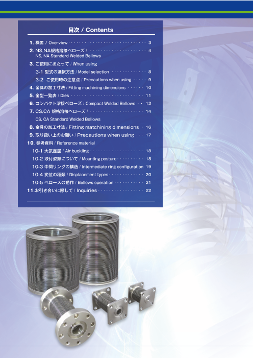
目次 / Contents
1. 概要 / Overview ・・・・・・・・・・・・・・・・・・・・・・・・・・・・・ 3
2. NS,NA規格溶接べローズ / ・・・・・・・・・・・・・・・・・・・・・ 4
NS, NA Standard Welded Bellows
3. ご使用にあたって / When using
3-1 型式の選択方法 / Model selection ・・・・・・・・・・・・・ 8
3-2 ご使用時の注意点 / Precautions when using ・・・・・ 9
4. 金具の加工寸法 / Fitting machining dimensions ・・・・・・ 10
5. 金型一覧表 / Dies ・・・・・・・・・・・・・・・・・・・・・・・・・・・ 11
6. コンパクト溶接ベローズ / Compact Welded Bellows ・・ 12
7. CS,CA 規格溶接べローズ / ・・・・・・・・・・・・・・・・・・・・ 14
CS, CA Standard Welded Bellows
8. 金具の加工寸法 / Fitting matchining dimensions ・ 16
9. 取り扱い上のお願い / Precautions when using ・・・ 17
10. 参考資料 / Reference material
10-1 大気座屈 / Air buckling ・・・・・・・・・・・・・・・・・・・・ 18
10-2 取付姿勢について / Mounting posture ・・・・・・・・・・ 18
10-3 中間リングの構造 / Intermediate ring confi guration 19
10-4 変位の種類 / Displacement types ・・・・・・・・・・・・・ 20
10-5 べローズの動作 / Bellows operation ・・・・・・・・・・・ 21
11.お引き合いに際して / Inquiries ・・・・・・・・・・・・・・・・・ 22
溶接ベローズカタログ_220_20180309.indd 2 2018/03/09 14:09:47
Page3
溶接ベローズ / WELDED BELLOWS
概要 / Overview
金属べローズは半導体・液晶・真空機器・加速器・核融合・原子力・石油化学・建築分野をは
じめとし、気体・流体の気密封止のシール用部材とし使用されております。その利用として、真
空中の搬送部に用いる大気とのシール材として、又「完全漏洩防止」シール材とし真空バルブや、
一般産業用のバルブへの採用が多くなってきております。
昨今では特殊な材質の要求や、べローズ表面のクリーン度、大型化、長寿命など年々高度な仕
様が求められています。
この度、カタログの改正に当たり今までご利用いただいておりました、IE 規格及び S,A 規格
をご使用の皆様が「より見やすく、より使いやすく」に重点を置き構成いたしました。更に、多
種多様な仕様に対応するべく、べローズの特性をはじめべローズの設計に際し必要となる技術資
料も掲載いたしました。量産製作により安定供給・低価格を実現いたしましたので、従来の規格
品に代わりご利用いただきますようお願いいたします。
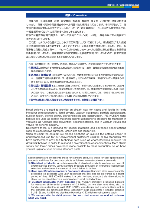
べローズ仕様に対して、規格品、応用品、特注品とに分けて、ご要求に対応させていただきます。
①規格品ご事情の許す限り規格品をご使用いただければ、納期・価格面で大変経済的な選択と納
期の短縮が計れます。
②応用品 (個別設計 )規格品サイズであれば、常時生産されておりますので個別設計品であって
も、短納期で対応が出来ます。又、標準金型寸法のものであれば、部材においては常備を心が
けておりますので、比較的短納期で対応が出来ます。
③特注品 ( 新規設計 )主に真空用(差圧 0.1MPa)を基本として生産をしておりますが、加圧用
としても対応が出来るよう、金型等を用意しております。又、標準金型寸法表にないもの(特に
大口径)でも、ご要求に応じ設計・生産いたします。材質につきましては、SUS316L,AM350
の他に、ハステロイC-22(高ニッケル鋼)の材料も用意しております。
※様々なご使用に対して対応させていただきますので、お気軽にご相談下さい。
Metal bellows are used to provide an airtight seal for gases and liquids in fields
including semiconductors, liquid crystal, vacuum equipment, particle accelerators,
nuclear fusion, atomic power, petrochemicals and construction. IRIE KOKEN metal
bellows are used as sealing materials against atmospheric pressure for transport in
vacuums, as "ultimate leak prevention" sealing materials, and in vacuum valves and
valves for general industry.
Nowadays there is a demand for special materials and advanced specifications
such as clean bellows surfaces, larger size and longer life.
When revising the catalog, we placed emphasis on making the catalog easier to
understand and use for our conventional customers using IE or S.A standards. We
have furthermore provided technical data such as characteristics required for
designing bellows in order to respond a diversifi cation of specifi cations. More stable
supply and lower prices have been made possible by mass production, so we hope
you will upgrade your existing standard parts.
Specifi cations are divided into those for standard products, those for user specifi cation
products and those for custom products as follows to meet customer's demands:
①Standard products A certain quantity of standard products are kept on hand. If
circumstances permit, using standard products provides an extremely economical
selection and reduces the amount of time it takes to deliver.
②User specifi cation products (separate design) Standard sizes are constantly
produced, so products with user specifications can also be delivered in a short
period of time. IRIE KOKEN makes it a point to keep standard die dimensions in
stock, so we can deliver in a comparatively short period of time.
③ Custom products (new design) IRIE KOKEN primarily produces bellows
for vacuums (differential pressure of 0.1 MPa), but we also have dies, etc., to
handle pressurization as well. IRIE KOKEN can design and produce items not in
the standard die dimensions table (especially large diameters) if needed. Besides
SUS316L and AM350, we also have Hastelloy C-22 (high-nickel content steel).
※ We can provide the right product for you. Just contact us and let us know
what you need.
3
溶接ベローズカタログ_220_20180309.indd 3 2018/03/09 14:09:50
Page4
NS,NA規格溶接べローズ
WELDED
NS,NA STANDARD WELDED BELLOWS
特 徴/Features
1. コンパクトで大きい伸縮量が得られる。 1.IRIE KOKEN welded bellows are compact and offer
2. バネ反力が小さい。 superior expansion/contraction.
2.Minimal spring force
3. 長寿命での使用が可能。 3.Long life
4. エンドフィッティングの選択が出来、設計に自由度がある。 4.Offers selection of end fitting to provide freedom of
5. Y型エンドフィッティング付きは、お客様での溶接が可能。 design.
6.取付け方向に制限がない。 5.The user can weld Y-type end fi tting.
6.No restriction on mounting orientation.
標準仕様/Standard Specifi cations
内 部 真 空
Internal Vacuum
外 部 大気圧
External Atmospheric pressure
使用温度 常 温(ベーキング温度250℃以下)
Operating temperature Normal temperature (baking temp. max. 250℃ )
He ガスリーク
リークテスト He gas leak
Leak test 1 × 10⁻⁹ Pa・m3 / s 以下
Max. 1 x 10⁻⁹ Pa・m3/s
べローズ材質 SUS316L, AM350 相当
Bellows material
繰り返し寿命 *1万回 , 10 万回 , 100 万回
Repetition life 10,000/100,000/1 million repetitions
* 1万回仕様は、SUS316L のみです。
* 10,000 repetitions specifi cation applies to SUS316L only.
型式表示方法/Ordering Number Description
ブロック数(1ブロックは10mmストローク)
Number of blocks(1 block= stroke/10mm)
NS 1 22 2 Y
べローズ外径 エンドフィッティング
Outer diameter of Bellows End fitting
寿命 Y Y型エンドフィッティング
Y-type end fitting
Life
材質 1万回 E 波型エンドフィッティング
Material 1 Corrugated end fitting
10,000 repetitions
NS SUS316L 10 10万回
100,000 repetitions
NA AM350 相当 100 100万回
1 million repetitions
〔上記の例は、寿命1万回、外径22(内径 8)伸縮量20mm、Y型エンドフィッティング付きを表します。〕
[The example provided above is of 20 mm expansion/contraction, and (22 outer diameter ( φ 8 inner diameter), with Y-type end fi tting.]
4
溶接ベローズカタログ_220_20180309.indd 4 2018/03/09 14:09:51
Page5
溶接ベローズ / WELDED BELLOWS
各部の名称/Name of parts
□有効径(内径+外径)/2 □ Eff ective diameter (inner + outer)/2
□ LMIN=最小面間 □ LMIN: Minimum length
□ LMAX=最大面間 □ LMAX: Maximum length
□ LY=エンドフィッティングの長さ □ LY: End fi tting length
LY LMIN~LMAX(自由長) LY
LMIN - LMAX (Unrestricted length)
Y型エンドフィッティング 波型エンドフィッティング
Y-type end fitting Corrugated end fitting
5
溶接ベローズカタログ_220_20180309.indd 5 2018/03/09 14:09:51
有効径
Effective diameter
内径
Inner diameter
外径
Outer diameter
Page6
NS規格溶接べローズ SUS316L/NS Standard Welded Bellows SUS316L
寿命1万回シリーズ / 10,000 repetition life series
1ブロック仕様 1 block specifications
型 式 内 径 外 径 作動範囲 軸方向バネ定数 有効面積 ブロック数最大
Model Inner diameter Outer diameter 自由長 Operating range(mm) Axial direction Effective area The maximum
(mm) (mm) Unrestricted spring constant number of blocks
length(mm) LMIN LMAX (N/mm)
NS122-1 8 22 15 7 17 3.29 1.77 4
NS130-1 17 30 13 6 16 5.82 4.34 6
NS136-1 22 36 12 5 15 5.57 6.61 8
NS151-1 36 51 10 4 14 7.13 14.9 12
NS170-1 50 70 9 4 14 10.41 28.3 15
NS190-1 60 90 9 4 14 11.07 44.2 13
NS194-1 70 94 10 5 15 12.80 52.8 14
NS1109-1 79 109 10 5 15 31.53 69.4 16
NS1120-1 90 120 10 5 15 27.75 86.6 17
NS1150A-1 100 150 10 5 15 31.21 122.7 17
NS1150B-1 120 150 10 5 15 23.50 143.1 19
NS1210-1 160 210 10 5 15 39.57 268.8 21
NS1270-1 206 270 9 4 14 30.20 444.9 15
NS1320-1 260 320 9 4 14 41.94 660.5 19
寿命10万回シリーズ / 100,000 repetition life series
1ブロック仕様 1 block specifications
型 式 内 径 外 径 作動範囲 軸方向バネ定数 有効面積 ブロック数最大
Model Inner diameter Outer diameter 自由長 Operating range(mm) Axial direction Effective area The maximum
(mm) (mm) Unrestricted
length(mm) spring constant number of blocks
LMIN LMAX (N/mm)
NS1022-1 8 22 23 15 25 2.14 1.77 2
NS1030-1 17 30 19 11 21 4.07 4.34 4
NS1036-1 22 36 18 10 20 3.72 6.61 5
NS1051-1 36 51 15 8 18 4.75 14.9 8
NS1070-1 50 70 15 7 17 6.62 28.3 10
NS1090-1 60 90 13 6 16 7.38 44.2 10
NS1094-1 70 94 11 6 16 11.38 52.8 13
NS10109-1 79 109 13 7 17 23.65 69.4 13
NS10120-1 90 120 13 7 17 20.81 86.6 14
NS10150A-1 100 150 15 8 18 20.81 122.7 13
NS10150B-1 120 150 13 7 17 17.63 143.1 16
NS10210-1 160 210 13 6 16 31.66 268.8 14
NS10270-1 206 270 15 7 17 18.12 444.9 11
NS10320-1 260 320 14 7 17 25.16 660.5 14
寿命100万回シリーズ / 1 million repetition life series
1ブロック仕様 1 block specifications
型 式 内 径 外 径 作動範囲 軸方向バネ定数 有効面積 ブロック数最大
Model Inner diameter Outer diameter 自由長 Operating range(mm) Axial direction Effective area The maximum
(mm) (mm) Unrestricted number of blocks
length(mm) spring constant
LMIN LMAX (N/mm)
NS10022-1 8 22 31 24 34 1.54 1.77 2
NS10030-1 17 30 25 18 28 3.02 4.34 3
NS10036-1 22 36 24 16 26 2.79 6.61 4
NS10051-1 36 51 22 14 24 3.39 14.9 5
NS10070-1 50 70 21 14 24 4.55 28.3 7
NS10090-1 60 90 17 10 20 5.53 44.2 8
NS10094-1 70 94 16 9 19 7.88 52.8 10
NS100109-1 79 109 18 10 20 17.20 69.4 10
NS100120-1 90 120 16 9 19 16.65 86.6 12
NS100150A-1 100 150 20 13 23 15.61 122.7 10
NS100150B-1 120 150 18 10 20 12.82 143.1 12
NS100210-1 160 210 18 10 20 22.61 268.8 13
NS100270-1 206 270 21 13 23 12.94 444.9 11
NS100320-1 260 320 17 10 20 20.97 660.5 15
6
溶接ベローズカタログ_220_20180309.indd 6 2018/03/09 14:09:52
Page7
溶接ベローズ / WELDED BELLOWS
NA規格溶接べローズ AM350/NA Standard Welded Bellows AM350
寿命10万回シリーズ / 100,000 repetition life series
1ブロック仕様 1 block specifications
型 式 内 径 外 径 作動範囲 軸方向バネ定数 有効面積 ブロック数最大
Model Inner diameter Outer diameter 自由長 Operating range(mm)
Unrestricted Axial direction Effective area The maximum
(mm) (mm)
length(mm) spring constant number of blocks
LMIN LMAX (N/mm)
NA1022-1 8 22 20 12 22 2.47 1.77 3
NA1030-1 17 30 16 8 18 4.79 4.34 5
NA1036-1 22 36 15 7 17 4.05 6.61 6
NA1051-1 36 51 13 6 16 5.97 14.9 9
NA1070-1 50 70 13 6 16 6.19 28.3 10
NA1090-1 60 90 11 5 15 7.40 44.2 11
NA1094-1 70 94 10 5 15 12.74 52.8 14
NA10109-1 79 109 11 6 16 27.02 69.4 15
NA10120-1 90 120 11 6 16 21.87 86.6 16
NA10150A-1 100 150 13 6 16 24.97 122.7 15
NA10150B-1 120 150 11 6 16 21.25 143.1 17
NA10210-1 160 210 10 5 15 39.57 268.8 21
NA10270-1 206 270 12 5 15 23.90 444.9 8
NA10320-1 260 320 11 5 15 33.19 660.5 10
寿命100万回シリーズ / 1 million repetition life series
1ブロック仕様 1 block specifications
型 式 内 径 外 径 作動範囲 軸方向バネ定数 有効面積 ブロック数最大
Model Inner diameter Outer diameter 自由長 Operating range(mm)
Unrestricted Axial direction Effective area The maximum
(mm) (mm) number of blocks
length(mm) spring constant
LMIN LMAX (N/mm)
NA10022-1 8 22 22 14 24 2.24 1.77 2
NA10030-1 17 30 18 10 20 4.29 4.34 5
NA10036-1 22 36 17 9 19 3.57 6.61 6
NA10051-1 36 51 14 7 17 5.54 14.9 9
NA10070-1 50 70 15 7 17 5.63 28.3 9
NA10090-1 60 90 13 6 16 6.58 44.2 10
NA10094-1 70 94 11 6 16 11.32 52.8 13
NA100109-1 79 109 11 6 16 27.02 69.4 15
NA100120-1 90 120 11 6 16 21.87 86.6 16
NA100150A-1 100 150 13 6 16 24.97 122.7 15
NA100150B-1 120 150 13 7 17 18.60 143.1 16
NA100210-1 160 210 13 6 16 31.66 268.8 14
NA100270-1 206 270 15 7 17 19.12 444.9 12
NA100320-1 260 320 14 7 17 26.55 660.5 14
エンドフィッティング(LY)長さ / End fitting length (LY)
Y型エンドフィッティング 波型エンドフィッティング
べローズサイズ Y-type end fitting Corrugated end fitting
Bellows size
LY LY
8 × 22 3 1.5
17 × 30 3 1.5
22. × 36 3 1.5
36 × 51 3 1.5
50 × 70 3 1.5
60 × 90 4 ―
70× 94 4 ―
79× 109 4 ―
90× 120 4 ―
100× 150 4 ―
120× 150 4 ―
160× 210 5 ―
206× 270 5 ―
260× 320 5 ―
※Y型エンドフィッティングの板厚は0.4mmとなります。
※Plate thickness of Y-type end fitting is 0.4 mm.
7
溶接ベローズカタログ_220_20180309.indd 7 2018/03/09 14:09:52
Page8
ご使用にあたって
WHEN USING
型式の選択方法/Model selection
仕様の確認 / Specifi cations check
⬇ 【標準仕様に適応しているか/ Suitable for standard specifi cations?】
材質の選択 / Model Material Features
型 式 材 質 特 長
Model M aterial Features
⬇ NS SUS316L 一般的に使用されている材質であり、耐食性に優れている。
Commonly used material. Has superior corrosion resistance.
NA AM350 相当 SUS316Lに比べ、寿命特性が良い。磁性体であり、耐食性が劣る。
Off ers longer life than SUS316L. A magnetizer with inferior corrosion resistance.
寿命の選択 / Life selection
型 式 寿 命 ※使用寿命が規格にない場合は、1ランク上のものをご使用下さい。
Model Life ※寿命が 100万回を越える場合は、個別設計が必要です。
※ If there is no standard for life, you should select one rank higher.
⬇ 1 1万回 10,000 repetitions ※ User specifications are required if life is to exceed 1 million
repetitions.
10 10 万回 100,000 repetitions
1 00 100万回 1 million repetitions
サイズの選択 / Size selection
型 式 サイズ 型 式 サイズ
Model Size Model Size
22 8 × 22 109 79 × 109
3 0 1 7 × 30 120 90 × 120
⬇ 36 22× 36 150A 100 × 150
51 36× 51 150B 120 × 150
70 50× 70 210 160 × 210
90 60× 90 270 206 × 270
94 70× 94 320 260× 320
ブロック数の算出 / Size selectionBlock number calculation
●ブロック数=必要ストローク/10mm
※ブロック数は、小数点以下切り上げとして下さい。
⬇ (表中の最大ブロック数を越える場合は、個別設計が必要です。)
●Number of blocks = required stroke / 10mm
※ Number of blocks is rounded up to the nearest whole number.
(User specifi cations are required if the maximum number of blocks given in the table is exceeded.)
8
溶接ベローズカタログ_220_20180309.indd 8 2018/03/09 14:09:52
Page9
溶接ベローズ / WELDED BELLOWS
エンドフィッティングの選択 / End fi tting selection
型 式 材 質 特 長
Model Material Features
Y Y型タイプ お客様で溶接される場合は、Y型タイプになります。
Y-type The Y-type must be used if the fi tting is to be welded on by the user.
⬇ E 波型タイプ Y型タイプより長さが短いので、コンパクトな設計ができます。
Corrugated type Shorter than the Y-type, thus enabling more compact design.
※波型タイプは、弊社での溶接のみと限らせていただきます。
※サイズ:内径60×外径 90以上は、波型タイプのエンドフィッティングは使用いたしません。
※Corrugated type can only be welded on at the factory.
※ Corrugated type cannot be used for size 60 (inner diameter) x 90 (outer diameter) or larger.
自由長・作動範囲の確認 / Unrestricted length/operating range check
□自由長=自由長(一覧表)×ブロック数+エンドフィッティング×2
□最大面間=LMAX(一覧表)×ブロック数+エンドフィッティング×2
⬇ □最小面間=LMIN(一覧表)×ブロック数+エンドフィッティング×2
□Unrestricted length: Unrestricted length (list) x number of blocks + end fi tting x 2
□ Between maximum areas: LMAX (list) x number of blocks + end fi tting x 2
□ Between minimum areas: LMIN (list) x number of blocks + end fi tting x 2
軸方向バネ定数の確認 / Axial direction spring constant check
□軸方向バネ定数=軸方向バネ定数(一覧表)/ブロック数
□Axial direction spring constant: Axial direction spring constant (list)/number of blocks
ご使用時の注意点/Precautions when using
1 ブロック数
表中の最大ブロック数は、※「大気座屈、水平たわみ、垂直密着」を考慮し、設定しております。最大ブロック数を越えて使用する場合には、
中間リングを別途設ける必要があります。尚、中間リングを使用した場合には、規格値の寿命が得られない場合がありますのでご注意下さい。
2 使用圧力
内部)真空、外部)大気圧にて設定しておりますので、それ以外の圧力では使用できません。尚、圧力変動がある場合にもご使用になれま
せんのでご注意下さい。
3 伸縮量及び寿命
表中にない伸縮量及び寿命につきましては、1ランク上のものをご使用いただくことをご推薦いたします。 個別の設計は可能ですが、規
格品は納期的にも価格的にも個別設計するより有利となります。
以上の内容にて、お困りの際はお気軽にご相談下さい。
※「大気座屈、垂直密着、水平たわみ」については、参考資料をご参照下さい。
1. Number of blocks
The maximum number of blocks in the table is set, taking "air buckling, horizontal sagging and vertical adherence" into consideration. An optional
intermediate ring must be provided if the maximum number of blocks is to be exceeded. Please be aware however that standard life may be reduced
if an intermediate ring is used.
2. Operating pressure
The bellows are designed for internal pressure to be a vacuum and external pressure to be atmospheric pressure. The bellows cannot be use under
pressure conditions other than this. The bellows also may not be used with pressure variation.
3. Expansion/contraction and life
We recommend using one rank above for expansion/contraction and life not given in the table. User specifi cations are possible, but standard
products are therefore advantageous in terms of fast delivery and lower price.
Feel free to contact us if you have any questions.
※ See the reference materials for more information on "air buckling, horizontal sagging and vertical adherence."
9
溶接ベローズカタログ_220_20180309.indd 9 2018/03/09 14:09:52
Page10
金具の加工寸法
FITTING MACHINING DIMENSIONS
Y型エンドフィッティング寸法及び溶接部開先寸法
Dimensions of welding groove for Y-type end fitting
溶接開先部寸法
0.5 1.4 べローズサイズ Welding groove dimensions
Bellows size
D A
面取り不可
Cannot be beveled 8 × 22 21.9 +0.2/0
17 × 30 30.1 +0.2/0
22 × 36 35.9 +0.2/0
36 × 51 50.9 +0.2/0
50 × 70 69.4 +0.2/0
60 × 90 89.4 +0.2/0
70 × 94 94.0 +0.2/0
79 × 109 108.9 +0.2/0
90 × 120 120.2 +0.2/0
100 × 150 149.3 +0.3/0
120 × 150 150.1 +0.2/0
160 × 210 209.2 +0.3/0
206 × 270 270.2 +0.3/0
260 × 320 320.1 +0.3/0
波型エンドフィッティングの溶接部開先寸法
Dimensions of welding groove for corrugated end fitting
溶接開先部寸法
0.5 1.4 べローズサイズ Welding groove dimensions
Bellows size
面取り不可 D A e f
Cannot be beveled
8 × 22 21.8 +0.2/0 C1.0 0.8
17 × 30 30.1 +0.2/0 C1.0 0.6
22 × 36 36.0 +0.2/0 C1.0 0.8
36 × 51 51.0 +0.2/0 C1.0 0.8
e 50 × 70 69.6 +0.2/0 C1.0 1.0
60 × 90 89.5 +0.2/0 C1.0 1.3
70 × 94 93.9 +0.2/0 C1.0 1.2
79 × 109 108.9 +0.2/0 C1.0 1.7
90 × 120 119.5 +0.2/0 C1.0 1.1
100 × 150 149.4 +0.3/0 C1.0 1.8
120 × 150 149.7 +0.2/0 C1.0 2.1
160 × 210 208.1 +0.3/0 C2.5 2.8
206 × 270 270.0 +0.3/0 C2.5 2.0
260 × 320 318.9 +0.3/0 C2.5 2.8
10
溶接ベローズカタログ_220_20180309.indd 10 2018/03/09 14:09:52
φD±A φD±A
f
0.7 0.7
Page11
溶接ベローズ / WELDED BELLOWS
金型一覧表
DIES
( は規格サイズを示す/Indicates standard size)
内 径 外 径 内 径 外 径
Inner diameter Outer diameter Inner diameter Outer diameter
6 13 100 150
8 18 102 118
8 22 105 130
10 18 105 135
11 24 115 145
12 26 120 150
13 22 130 190
14 29 135 165
14 34 140 170
16 24 150 180
16 40 150 190
17 30 157 204
17 33 160 210
20 40 170 200
22 36 180 210
25 45 180 220
27 38 195 230
27 45 206 270
28 44 216 286
30 51 238 270
35 55 247 300
36 51 260 320
40 60 305 375
45 65 310 350
50 70 310 360
52 72 330 372
60 90 349 415
66 82 350 390
70 94 370 430
75 100 400 460
79 109 425 515
80 105 500 540
80 112 500 600
84.5 104.5 590 690
89 108 700 800
90 120 800 900
97 110 900 998
100 130
11
溶接ベローズカタログ_220_20180309.indd 11 2018/03/09 14:09:53
Page12
コンパクトに磨きあげられたトップメーカーの信頼性
30年のノウハウの蓄積が結集されたコンパクト溶接べローズを規格化しました。
A name you can trust, highly refining toward compact
Standardized compact welded bellows incorporate 30 years of experience
コンパクト溶接ベローズ
COMPACT
COMPACT WELDED BELLOWS
用 途/Purpose
主に半導体等における昇降用のシール
Seals used for elevating and lowering mainly for semiconductors, etc.
特 徴/Features
保証寿命1000万回を 30%のコストダウンを 高 信 頼 性 を 実 現!
実 現! ( 国 内 初 ) 実 現! ( 当 社 比 ) ISO9001 認 証 取 得
Realizes guaranteed life of 10 million Cuts cost by 30% High reliability!
repetitions (fi rst in Japan)! (compared with our products)! ISO9001 certifi cation obtained
1. 一山あたりのストローク(作動範囲)が従来の30%以上アップし、経済性を実現しました。
2. コンパクトで大きい伸縮量が得られます。
3. バネ反力が小さい。
4. エンドフィッティングの選択が出来、設計に自由度があります。
5. Y型エンドフィッティング付は、お客様での溶接が可能です。
(べローズサイズφ8×φ22~φ90×φ120と巾広いサイズをラインナップ)
1.30% better per-thread stroke (operating range) makes IRIE KOKEN welded bellows more economical.
2.IRIE KOKEN welded bellows are compact and off er superior expansion/contraction.
3.Minimal spring force
4.Off ers selection of end fi tting to provide freedom of design
5.The user can weld Y-type end fi tting
(Wide lineup of bellows sizes from φ 8 x φ 22 to φ 90 x φ 120)
型式表示方法/Ordering Number Description
べローズ外径
Outer diameter of Bellows
CS 1000 2 22 Y
ストローク
Stroke
材質 寿命 エンドフィッティング
Material Life End fitting
CS SUS316L 1000 1,000万回 Y Y型エンドフィッティング
10 million repetitions Y-type end fitting
CA AM350 相当 E 波型エンドフィッティング
Corrugated end fitting
12
溶接ベローズカタログ_220_20180309.indd 12 2018/03/09 14:09:53
Page13
コンパクト溶接ベローズ / COMPACT WELDED BELLOWS
標準仕様/Standard Specifi cations
内 部 真 空
Internal Vacuum
外 部 大気圧
External Atmospheric pressure
使用温度 常 温(ベーキング温度250℃以下)
Operating temperature Normal temperature (baking temp. max. 250℃ )
He ガスリーク
リークテスト He gas leak
Leak test 1 × 10⁻⁹ Pa・m3 / s 以下
Max. 1 x 10⁻⁹ Pa・m3/s
べローズ材質
Bellows material SUS316L, AM350 相当
繰り返し寿命 *1,000万回
Repetition life 10 million repetitions
各部の名称/Name of parts
□有効径(内径+外径)/2 □ Eff ective diameter (inner + outer)/2
□ LMIN=最小面間 □ LMIN: Minimum length
□ LMAX=最大面間 □ LMAX: Maximum length
□ LY=エンドフィッティングの長さ □ LY: End fi tting length Y型エンドフィッティング
Y-type end fitting
LY LMIN~LMAX(自由長) LY
LMIN - LMAX (Unrestricted length)
13
溶接ベローズカタログ_220_20180309.indd 13 2018/03/09 14:09:53
有効径
Effective diameter
内径
Inner diameter
外径
Outer diameter
Page14
CS規格溶接べローズ SUS316L/CS Standard Welded Bellows SUS316L
20mmストローク用べローズ/20 mm stroke bellows
1ブロック仕様 1 block specifications
型 式 内 径 外 径 作動範囲 有効面積
Model Inner diameter Outer diameter 自由長 Operating range 軸方向バネ定数 Effective area
(mm) (mm) Unrestricted (mm) Axial direction (cm2)
length spring constant
(mm) (N/mm)
LMIN LMAX
CS1000222 8 22 49 29 49 1.77 1.77
CS1000230 17 30 47 27 47 1.90 4.34
CS1000236 22 36 45 25 45 2.12 6.61
CS1000251 36 51 42 22 42 2.88 14.86
CS1000260 40 60 41 21 41 3.73 19.63
CS1000270 50 70 42 22 42 3.80 28.27
CS1000290 60 90 47 27 47 3.99 44.18
CS1000294 70 94 43 23 43 5.60 52.81
CS10002109 79 109 46 26 46 9.74 69.40
CS10002120 90 120 41 21 41 12.60 86.59
30mmストローク用べローズ/30 mm stroke bellows
1ブロック仕様 1 block specifications
型 式 内 径 外 径 作動範囲 有効面積
Inner diameter Outer diameter 自由長
Model Operating range 軸方向バネ定数 Effective area
(mm) (mm) Unrestricted 2
(mm) Axial direction (cm )
length spring constant
(mm) (N/mm)
LMIN LMAX
CS1000322 ※ 8 22 72 42 72 1.19 1.77
CS1000330 17 30 69 39 69 1.27 4.34
CS1000336 22 36 67 37 67 1.43 6.61
CS1000351 36 51 63 33 63 1.90 14.86
CS1000360 40 60 59 29 59 2.56 19.63
CS1000370 50 70 60 30 60 2.57 28.27
CS1000390 60 90 66 36 66 2.75 44.18
CS1000394 70 94 62 32 62 3.73 52.81
CS10003109 79 109 65 35 65 6.63 69.40
CS10003120 90 120 59 29 59 8.40 86.59
※ CS1000322は大気動作で座屈しますので、ご使用の際は充分ご注意下さい。
※CS1000322 buckles by air operation. Be sure to keep this in mind when using.
14
溶接ベローズカタログ_220_20180309.indd 14 2018/03/09 14:09:54
Page15
コンパクト溶接ベローズ / COMPACT WELDED BELLOWS
CA規格溶接べローズ AM350/CA Standard Welded Bellows AM350
20mmストローク用べローズ/20 mm stroke bellows
1ブロック仕様 1 block specifications
型 式 内 径 外 径 作動範囲 有効面積
Model Inner diameter Outer diameter 自由長 Operating range 軸方向バネ定数 Effective area
(mm) (mm) Unrestricted (mm) Axial direction (cm2)
length spring constant
(mm) (N/mm)
LMIN LMAX
CA1000222 8 22 30 16 36 3.17 1.77
CA1000230 17 30 29 14 34 3.27 4.34
CA1000236 22 36 28 12 32 3.43 6.61
CA1000251 36 51 27 11 31 4.93 14.86
CA1000260 40 60 27 12 32 5.49 19.63
CA1000270 50 70 26 11 31 6.26 28.27
CA1000290 60 90 27 11 31 7.59 44.18
CA1000294 70 94 28 13 33 8.87 52.81
CA10002109 79 109 31 14 34 15.74 69.40
CA10002120 90 120 28 14 34 21.93 86.59
30mmストローク用べローズ/30 mm stroke bellows
1ブロック仕様 1 block specifications
型 式 内 径 外 径 作動範囲 有効面積
Inner diameter Outer diameter 自由長 Operating range 軸方向バネ定数
Model Effective area
(mm) (mm) Unrestricted (mm) Axial direction (cm2)
length spring constant
(mm) (N/mm)
LMIN LMAX
CA1000322 8 22 43 22 52 2.13 1.77
CA1000330 17 30 42 19 49 2.12 4.34
CA1000336 22 36 42 17 47 2.29 6.61
CA1000351 36 51 38 15 45 3.35 14.86
CA1000360 40 60 39 15 45 3.74 19.63
CA1000370 50 70 38 15 45 4.17 28.27
CA1000390 60 90 36 14 44 5.42 44.18
CA1000394 70 94 38 16 46 6.26 52.81
CA10003109 79 109 41 18 48 11.24 69.40
CA10003120 90 120 40 18 48 14.10 86.59
15
溶接ベローズカタログ_220_20180309.indd 15 2018/03/09 14:09:54
Page16
金具の加工寸法
FITTING MACHINING DIMENSIONS
Y型エンドフィッティング寸法及び溶接部開先寸法
Dimensions of welding groove for Y-type end fitting
単位 (Unit):mm
寸 法
べローズ サイズ Dimensions
0.5 1.4 Bellows size
D2 LY
LY 面取り不可
Cannot be beveled 8× 22 22.2 3
17× 30 30.3 3
22× 36 36.2 3
36× 51 51.0 3
40× 60 59.6 3
50× 70 69.4 3
60× 90 89.4 4
70× 94 93.9 4
79× 109 108.9 4
90× 120 120.0 4
※Y型エンドフィッティングの板厚は0.4mmとなります。
※Plate thickness of Y-type and fitting is 0.4 mm.
波型エンドフィッティングの溶接部開先寸法
Dimensions of welding groove for corrugated end fitting
単位 (Unit):mm
寸 法
べローズ サイズ Dimensions
0.5 1.4 Bellows size
D1 e f
面取り不可
Cannot be beveled 8× 22 22.2 C1 0.7
17 × 30 30.3 C1 0.7
22 × 36 36.2 C1 0.7
e 36× 51 51.0 C1 0.8
40 × 60 59.6 C1 0.8
50 × 70 69.7 C1 0.8
60 × 90 89.6 C2 1.1
70 × 94 93.8 C2 1.1
79 × 109 108.9 C2 1.4
90 × 120 120.0 C2 1.4
16
溶接ベローズカタログ_220_20180309.indd 16 2018/03/09 14:09:54
(φD1) (φD2)
+0.2
φD1 0
φD2 +0.2
f 0
0.7 0.7
Page17
コンパクト溶接ベローズ / COMPACT WELDED BELLOWS
取り扱い上のお願い
PRECAUTIONS WHEN USING
弊社べローズは、性能、品質ともにお客様のご要求に充分お答えできるものと確信しておりますが、取り扱いを誤ります
とべローズの特性を充分発揮できなくなるばかりか、耐久性を著しく縮めたり極端な場合は、損傷のため据え付け時から
使用できない場合があります。品質保証上の観点より、製品の取り扱いには下記事項について充分ご配慮をお願いいたし
ます。
1. 検収について 製品が到着しましたら、まずご注文通りの品物かどうかご確認ください。べローズは仕様書に基づいて、
細部にわたり検査し出荷しておりますが、御社到着までの輸送中の取り扱い等により万一変形等が起こる場合も考えられ
ますので、到着後直ちに検収を行って下さい。尚、ポリ袋からの開封は、ゴミ・粉塵のない環境下で行って下さい。(ゴミ・
粉塵がべローズの内部や谷間に混入しますと、早期破損の原因になります。)
2. 保管について 製品を長期にわたり保管する場合は、外力による変形防止はもちろんのこと、ゴミ・粉塵の付着、直射
日光への暴露などの防止とともに、発錆環境中(高湿度、塩害、腐食性物質を含む大気との接触)での保管は避けて下さい。
3. 運搬について 製品を運搬する場合は、納入時の荷姿で運搬することをお奨めいたします。万一、製品単体で運搬され
る場合は、傷を付けたり、曲げたり、あるいは衝撃を与えて変形することのないよう、充分注意して取り扱って下さい。
4. 取り付けについて 製品を取り付ける際、特にべローズにねじれが加わらないように取り付けて下さい。べローズの特
性上回転やねじり方向に変位させることはできません。又、軸芯がずれたり、ご指定寸法以外の長さでは取り付けないで
下さい。(寿命低下の原因となります。)べローズの損傷が最も多いのは、ボルト締め付け時のスパナ等の工具による打ち
傷や、べローズ内部にシャフトが通る場合に安易に差し込み、傷を付けてしまう場合があります。特に内部については、取
り付け後の確認ができませんので充分な注意が必要です。
5. 使用範囲について 使用範囲(圧力、伸縮量等)は、仕様書あるいはカタログに記載している範囲内で使用して下さい。
使用範囲を超えて使用しますと、早期破損の原因になるばかりか、事故の原因にもなりますので充分確認をしてご使用下
さい。
IRIE KOKEN is confident that our bellows offer the required performance and quality to satisfy your
needs. If not handled
properly, not only will the product not function to its full capability, but in extreme cases durability could
be dramatically affected as well. This could result in damage, rendering the product unusable before
it is even mounted. In order to ensure quality, be sure to heed the following advice when handling the
product.
1. Examine the product when delivered. When you receive the product, first make sure it's what you
ordered. The bellows are inspected in detail prior to delivery to make sure they conform to specifications,
but could become deformed during transport, so be sure to check the product immediately after you
receive it. Be sure to remove the product from its plastic bag in a place free of dust and dirt. (If dust or dirt
gets inside the bellows or in the grooves it could result in premature damage.
2. Storage If the product is to be stored for an extended period of time, be sure to store in a place free
from external force (to prevent deformation) where it is not exposed to dust, dirt or direct sunlight.
Corrosive environments should also be avoided (place subject to excessive humidity, salt or other
corrosive materials)
3. TransportFor subsequent transport, we recommend using the packaging in which the product was
delivered. If the product happens to be delivered by itself, handle with care to avoid damaging, bending, or
deforming the product by exposing it to impact.
4. Mounting Be sure not to twist the bellows when mounting. The characteristics of the product
does not allow displacement by turning or twisting. Do not alter the center alignment or mount
at length other than the specified dimension. (Doing so could reduce life of the product.)
Most damage to bellows is caused by bumping with tools such as a spanner when tightening bolts. If
a shaft is to pass through the bellows, the bellows can be damaged when the shaft is easily inserted.
Particular attention should be paid when doing so because the inside cannot be checked once the product
is mounted.
5. Usage range The product should be used within the range (pressure, expansion/contraction, etc.) given
in the specifications or catalog. Particular attention should be paid as it could result in premature damage
or accident if usage exceeds the usage range.
17
溶接ベローズカタログ_220_20180309.indd 17 2018/03/09 14:09:54
Page18
参考資料
REFERENCE MATERIAL
①大気座屈 / Air buckling
べローズは自由長から縮み側へ変位させると、バネ性により伸びようとする反力が発生いたします。しかし、その反力をべロー
ズ自体で吸収できなくなると変形(曲がる)いたします。その際、圧力(外力)が掛かっていない状態で変位させた場合に変形
することを“大気座屈”と言います。
各種装置においては必ず大気中で、試運転(動作確認)を行うものでありその際、大気座屈をおこすことにより、内部シャフト
に干渉したりシャフトがない場合には大きく変形してしまいます。その様な現象を起こしてしまうと、極端に寿命が低下する場
合があるため、中間リングを設けて座屈を防止いたします。
If the bellows are displaced from unrestricted length to contraction, spring characteristics cause a reaction force that
makes the bellows attempt to expand. If this reaction force is not absorbed by the bellows, it will become deformed (bent).
At this time, deformation by displacement when pressure (external force) is not applied is called "air buckling."
Trial operation (operation check) is always carried out for all types of equipment in the atmosphere. Air buckling at this
time will cause the bellows to interfere with the shaft inside or will cause it to become grossly deformed if it contains
no shaft. If this happens, it could cause life to deteriorate dramatically. Buckling is therefore prevented by providing an
intermediate ring.
②取付け姿勢について / Mounting posture
べローズは取付けの状態において、自重によりそれぞれ水平たわみ・垂直密着が発生いたします。
水 平 た わ み: べロースを水平に取付た際に、自重により中央部にたわみが生じます、たわみが大きくなると、べローズに軸
直角方向の変位が加わり早期破損の原因となります、弊社基準では、大気圧時のたわみ量が社内規定値以上に
なる場合、中間リングによりたわみを防止しています。
垂 直 密 着 : べローズを垂直に取付けた際に、自重により最下部山が最も縮み、最上部山が最も開きます。その状態で縮み
側に変位させますと、最下部山の隙間量< 1山あたりの変位量になる場合があります。その場合、最下部山
が密着してしまい、不足分の伸縮量を最高部山が補うことになります。そうなると計算値以上の変位が加わる
ことになり、寿命が低下します。そのため、中間リングと過伸縮防止用の構造を設ける必要があります。
Because of the condition of bellows when mounted, horizontal sagging and vertical adherence can be caused by the
bellows' own weight.
Horizontal sagging: When the bellows are mounted horizontally, sagging can develop in the center due to dead weight of
the bellows. If sagging is excessive, it adds to displacement in the perpendicular direction to an axis
and could result in premature damage. If sagging at atmospheric pressure exceeds IRIE KOKEN
standards, sagging is prevented by using an intermediate ring.
Vertical adherence: When the bellows are mounted vertically, the weight of the bellows causes the bottom part to
contact excessively and thetop to expand excessively. If displaced to the contraction side, the
bottom thread can be displaced less then an entire thread.
If this occurs, the bottom thread can stick to the base, with the uppermost threads having
to compensate for the lack of expansion/contraction. This results in more displacement than
calculated being added, consequently reducing life of the product. To prevent this requires an
intermediate ring and configuration that prevents excessive expansion/contraction.
水平たわみ
Horizontal sagging
垂直密着
※中間リングの構造は、P19をご参照下さい。 Vertical adherence
※See page 19 for configuration of the intermediate ring.
18
溶接ベローズカタログ_220_20180309.indd 18 2018/03/09 14:09:54
Page19
溶接ベローズ / WELDED BELLOWS
③中間リングの構造 / Intermediate ring confi guration
中間リング べローズ フランジ
Intermediate ring Bellows Flange
シャフト
Shaft
内部ガイド
Internal guide
中間リング
Intermediate ring
リニアブッシュ シャフト フランジ
Linear bushing べローズ Shaft Flange
Bellows
外部ガイド
External guide
縮み防止ストッパー
Contraction
prevention stopper
縮み防止ストッパー
Contraction リニアブッシュ
prevention stopper Linear bushing
中間リング 伸び防止ロッド 中間リング
Expansion 伸び防止ロッド
Intermediate ring Intermediate ring
prevention rod Expansion
prevention rod
べローズ べローズ
Bellows Bellows
シャフト シャフト
Shaft Shaft
フランジ フランジ
Flange Flange
内部ガイド+過伸縮防止構造 外部ガイド+過伸縮防止構造
Internal guide + configuration for preventing excessive expansion/contraction External guide + configuration for preventing excessive expansion/contraction
19
溶接ベローズカタログ_220_20180309.indd 19 2018/03/09 14:09:55
Page20
④変位の種類 / Displacement types
変位の種類には、下記の 3 種類があります。
Displacement includes the following three types
軸 方 向 変 位 Axial displacement
軸 直 角 変 位 Perpendicular to an axis displacement
角 度 変 位 Angular displacement
※実際の動作については、P21をご参照下さい。
※ For actual operation, see page 21.
又、変位の仕方には、単独変位・複合変位・オフセット変位があり、一般的には単独変位が大半ではありますが、寿命に大き
く影響するため十分な注意と検討が必要です。
下図に変位の考え方を記載いたします。
Displacement includes single, complex and offset displacement. The majority of displacement is single
displacement. This could have a large impact on life and therefore cares and considerations must be taken. The thinking
behind displacement is illustrated by the following figure.
単独変位 複合変位 オフセット変位
Single displacement Complex displacement Offset displacement
20
溶接ベローズカタログ_220_20180309.indd 20 2018/03/09 14:09:55