DATA SHEET
Type 8098
FLOWave
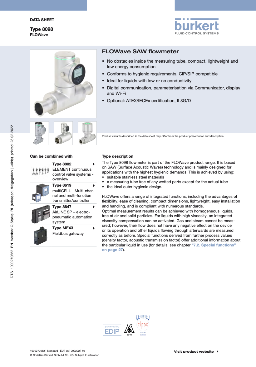
FLOWave SAW flowmeter
• No obstacles inside the measuring tube, compact, lightweight and
low energy consumption
• Conforms to hygienic requirements, CIP/SIP compatible
• Ideal for liquids with low or no conductivity
• Digital communication, parameterisation via Communicator, display
and Wi-Fi
• Optional: ATEX/IECEx certification, II 3G/D
Product variants described in the data sheet may differ from the product presentation and description.
Can be combined with Type description
Type 8802 The Type 8098 flowmeter is part of the FLOWave product range. It is based
ELEMENT continuous on SAW (Surface Acoustic Waves) technology and is mainly designed for
control valve systems - applications with the highest hygienic demands. This is achieved by using:
overview • suitable stainless steel materials
• a measuring tube free of any wetted parts except for the actual tube
Type 8619 • the ideal outer hygienic design.
multiCELL - Multi-chan-
nel and multi-function FLOWave offers a range of integrated functions, including the advantages of
transmitter/controller flexibility, ease of cleaning, compact dimensions, lightweight, easy installation
Type 8647 and handling, and is compliant with numerous standards.
AirLINE SP – electro- Optimal measurement results can be achieved with homogeneous liquids,
pneumatic automation free of air and solid particles. For liquids with high viscosity, an integrated
system viscosity compensation can be activated. Gas and steam cannot be meas-
ured; however, their flow does not have any negative effect on the device
Type ME43 or its operation and other liquids flowing through afterwards are measured
Fieldbus gateway correctly as before. Special functions derived from further process values
(density factor, acoustic transmission factor) offer additional information about
the particular liquid in use (for details, see chapter “7.2. Special functions”
on page 27).
28-06
1000270652 | Standard | EU | en | 202202 | 16 Visit product website
© Christian Bürkert GmbH & Co. KG, Subject to alteration
Type 8098
Table of contents
1. General technical data 4
1.1. About the FLOWave flowmeter ..............................................................................................................................................4
1.2. All versions .............................................................................................................................................................................4
1.3. FLOWave L flowmeter............................................................................................................................................................8
With or without industrial communication .............................................................................................................................8
With industrial communication (Ethernet version) ...............................................................................................................10
1.4. FLOWave S flowmeter .........................................................................................................................................................11
2. Approvals 13
2.1. Certification ..........................................................................................................................................................................13
2.2. Certificates ...........................................................................................................................................................................13
2.3. Pressure Equipment Directive ..............................................................................................................................................14
Device used on a pipe .........................................................................................................................................................14
3. Materials 14
3.1. Chemical Resistance Chart – Bürkert resistApp..................................................................................................................14
3.2. Material specifications .........................................................................................................................................................15
FLOWave L flowmeter without industrial communication ...................................................................................................15
FLOWave L flowmeter with industrial communication ........................................................................................................16
FLOWave S flowmeter .........................................................................................................................................................17
4. Dimensions 18
4.1. Transmitter of the FLOWave L flowmeter without industrial communication ......................................................................18
4.2. Transmitter of the FLOWave L flowmeter with industrial communication ...........................................................................18
4.3. Transmitter of the FLOWave S flowmeter ............................................................................................................................18
4.4. Flowmeter with clamp process connection .........................................................................................................................19
4.5. Flowmeter with aseptic collar flange (BF) ............................................................................................................................21
4.6. Flowmeter with aseptic collar clamp (BKS) .........................................................................................................................22
4.7. Flowmeter with thread connection ......................................................................................................................................23
5. Performance specifications 23
5.1. Medium temperature............................................................................................................................................................23
5.2. Measurement deviation .......................................................................................................................................................24
6. Product installation 25
6.1. Installation notes ..................................................................................................................................................................25
6.2. Selection of the nominal diameter .......................................................................................................................................25
6.3. Mounting options .................................................................................................................................................................26
FLOWave L flowmeter..........................................................................................................................................................26
FLOWave S flowmeter .........................................................................................................................................................26
7. Product operation 27
7.1. Measuring principle .............................................................................................................................................................27
7.2. Special functions .................................................................................................................................................................27
8. Product design and assembly 28
8.1. Product assembly ................................................................................................................................................................28
9. Product accessories 29
Visit product website 2 | 40
Type 8098
10. Ordering information 29
10.1. Bürkert eShop – Easy ordering and quick delivery ..............................................................................................................29
10.2. Recommendation regarding product selection ...................................................................................................................29
10.3. Bürkert product filter ............................................................................................................................................................30
10.4. Bürkert 3D Model - Interactive Animation ...........................................................................................................................30
10.5. Ordering chart FLOWave L flowmeter with or without industrial communication ...............................................................31
Clamp process connection acc. to DIN 32676 series A for pipe acc. to DIN 11866 series A (DIN 11850) .........................31
Clamp process connection acc. to DIN 32676 series B for pipe acc. to DIN 11866 series B (ISO 1127) ...........................32
Clamp process connection acc. to DIN 32676 series C for pipe acc. to DIN 11866 series C (ASME BPE) .......................33
Thread process connection acc. to DIN 11851 series A for pipe acc. to DIN 11866 series A (DIN 11850) ........................34
10.6. Ordering chart FLOWave S flowmeter .................................................................................................................................35
Clamp process connection acc. to DIN 32676 series A for pipe acc. to DIN 11866 series A (DIN 11850) .........................35
Clamp process connection acc. to DIN 32676 series B for pipe acc. to DIN 11866 series B (ISO 1127) ...........................36
Clamp process connection acc. to DIN 32676 series C for pipe acc. to DIN 11866 series C (ASME BPE) .......................37
Thread process connection acc. to DIN 11851 series A for pipe acc. to DIN 11866 series A (DIN 11850) ........................38
10.7. Ordering chart accessories ..................................................................................................................................................39
Visit product website 3 | 40
Page4
1. General technical data、1.1. About the FLOWave flowmeter、1.2. All versions
Type 8098
1. General technical data
1.1. About the FLOWave flowmeter
The flowmeter Type 8098 consists of:
• either a flow sensor Type S097 and a transmitter Type SE98 (version FLOWave L flowmeter), which is available with or without
industrial communication (the FLOWave L version with industrial communication, recognisable by the two M12 female connectors
and the M12 male connector, is called the Ethernet version.)
• or a flow sensor Type S097 and a transmitter Type SE91 (version FLOWave S flowmeter)
1.2. All versions
The following data applies to all versions.
Product properties
Material
Please make sure the device materials are compatible with the fluid you are using.
Detailed information can be found in chapter “3.1. Chemical Resistance Chart – Bürkert resistApp” on page 14.
Detailed information on the materials can be found in chapter “3.2. Material specifications” on page 15.
Non wetted parts
Sensor housing • For sensor with process connection ≤ DN 50/2": stainless steel 304/1.4301
• For sensor with process connection > DN 50/2": stainless steel 316L/1.4435
Wetted parts
Measurement tube and clamp Stainless steel 316L/1.4435 with low delta ferrite content
Dimensions Detailed information can be found in chapter ““4. Dimensions” on page 18.
Surface quality
Measurement tube (inner surface) • Ra < 0.8 µm (30 µin.) or
• Ra < 0.4 µm (15 µin.) (electro-polished) according to ISO 4288
Measurement tube (outer surface), Ra < 1.6 µm (excluding welding seams) according to ISO 4288
housing
Measuring range
Volume flow rate measurement 0…1.7 m3/h up to 0…200 m3/h
Detailed information can be found in chapter “10.5. Ordering chart FLOWave L flowmeter
with or without industrial communication” on page 31 or “10.6. Ordering chart FLO-
Wave S flowmeter” on page 35.
Temperature measurement - 20…+ 140 °C (- 4…+ 284 °F)
Visit product website 4 | 40
Type 8098
Special function • ATF: acoustic transmission factor
• DF: density factor
Active by default, deselectable upon request. Detailed information can be found in chapter
“7.2. Special functions” on page 27.
Performance data
Volume flow rate measurement
Under reference conditions i.e. measuring fluid = water free from gas bubbles and solids, ambient and water temperature = 23 °C
± 1 °C (73.4 °F ± 1.8 F), and short refresh time, while maintaining turbulent or laminar flow profile, with the minimum inlet (40 x DN)
and outlet (1 x DN) distances and the appropriate internal diameter of the pipes. Deviation from reference conditions can be adjust-
ed through the use of a built-in correction K factor adjustment or Teach-in Procedure.
Measurement deviation • From 10 % of full scale up to full scale: ± 0.4 % of the measured value
• From 1 % of full scale up to 10 % of full scale: ± 0.08 % of full scale
Detailed information can be found in chapter “5.2. Measurement deviation” on page 24.
Repeatability • From 10 % of full scale up to full scale: ± 0.2 % of the measured value
• From 1 % of full scale up to 10 % of full scale: ± 0.04 % of full scale
Refresh time Selectable:
• Very short (~ 30 ms)
• Short (~ 55 ms)
• Long (~ 100 ms)
Temperature measurement
Measurement deviation • For T° ≤ 100 °C (+ 212 °F): ± 1 °C (+ 1.8 °F)
• For 100 °C (+ 212 °F) < T° < 140 °C (+ 284 °F): ± 1.5 %
Refresh time Approx. 0.1 s
Electrical data
Operating voltage • 12…35 V DC filtered and regulated
• Tolerance: ± 10 %
• Connection to main supply: permanent (through external SELV (Safety Extra Low Voltage)
and LPS (Limited Power Source) power supply)
Power source (not supplied) Limited power source according to UL/EN 60950-1 standards or limited energy circuit accord-
ing to UL/EN 61010-1 §9.4
DC reverse polarity protection Yes
Voltage supply cable
For cable glands • 0.2…1.5 mm2 cross-section
• In nickel plated brass:
– Cable with maximum operating temperature greater than + 80 °C (+ 176 °F)
– 5…14 mm diameter, shielded cable
• In stainless steel:
– Cable with maximum operating temperature greater than + 80 °C (+ 176 °F)
– 6…12 mm diameter, shielded cable
For 5 pin M12 male connector • Cable with maximum operating temperature greater than + 80 °C (+ 176 °F)
(A-coded) • 3…6.5 mm diameter, shielded cable,
• 0.75 mm2 cross-section to connect to 5 pin M12 female connector (A-coded, not supplied)
For 4 pin M12 female connector • Cable with maximum operating temperature greater than + 80 °C (+ 176 °F)
(D-coded) • 5e / CAT-5 min. category, 100 m max. length, shielded conductor with minimum STP
Medium data
Fluid Non-dangerous liquids complying with article 4, §1 of 2014/68/EU directive. Detailed informa-
tion can be found in chapter “2.3. Pressure Equipment Directive” on page 14.
By default the FLOWave flowmeter is set for a fluid with a sound velocity1.)
• between 1000 m/s and 2000 m/s for process connection DN 08, ⅜" and ½"
• between 800 m/s and 2300 m/s for process connection DN ≥ 15 or ≥ ¾"
Visit product website 5 | 40
Type 8098
Fluid temperature • - 20…+ 110 °C (- 4…+ 230 °F). The maximum fluid temperature can be restricted by the
ambient operating temperature.
• Max. conditions for sterilisation process: up to + 140 °C (+ 284 °F) (+ 130 °C (+ 266 °F) for
ATEX/IECEx version) for max. 60 min
• Maximum temperature gradient: 10 °C/s (18 °F/s) (measured by the integrated sensor on the
device)
Fluid pressure (max.)
DN / Pipe standard DIN 11850 ISO 1127 ASME BPE SMS 3008
DN 08, ⅜", ½" PN 25 PN 25 PN 25 –
DN 15, ¾", DN 25, 1" PN 25 PN 25 PN 25 PN 25
DN 40 PN 25 PN 16 – PN 25
1½", DN 50, 2" PN 16 PN 16 PN 16 PN 16
DN 65, 2½", DN 80, 3" PN 10 PN 10 PN 10 –
Process/Port connection & communication
Process connection / pipe size2.) according to
DIN 32676 series A / DIN 11850 Clamp: DN 08, DN 15, DN 25, DN 40, DN 50, DN 65 and DN 80
DIN 32676 series B / ISO 1127 Clamp: DN 08, DN 15, DN 25, DN 40, DN 50, DN 65 and DN 80
DIN 32676 series C / ASME BPE Clamp: ⅜", ½", ¾", 1", 1½", 2", 2½" and 3"
DIN 11864-2 form A series A / Aseptic collar flange (BF)3.): DN 15, DN 25, DN 40 and DN 50
DIN 11850
DIN 11864-2 form A series B / Aseptic collar flange (BF)3.): DN 08, DN 15, DN 25, DN 40 and DN 50
ISO 1127
DIN 11864-2 form A series C / Aseptic collar flange (BF)3.): ½", ¾", 1", 1½" and 2"
ASME BPE
DIN 11864-3 form A series A / Aseptic collar clamp (BKS)3.): DN 15, DN 25, DN 40 and DN 50
DIN 11850
DIN 11864-3 form A series B / Aseptic collar clamp (BKS)3.): DN 08, DN 15, DN 25, DN 40 and DN 50
ISO 1127
DIN 11864-3 form A series C / Aseptic collar clamp (BKS)3.): ½", ¾", 1", 1½" and 2"
ASME BPE
SMS 3017 / SMS 3008 Clamp: DN 25, DN 40 and DN 50
DIN 11851 series A / DIN 11850 Thread: DN 65 and DN 80
Device status LED light ring according to NAMUR NE 107
Approvals and Certificates
Standards
Degree of protection4.) IP65, IP67 (according to IEC/EN 60529), NEMA 4X (according to NEMA250), if the product is
wired and if the cable glands are tightened and the covers are screwed tight. Unused cable
glands must be sealed with the stopper gaskets provided (mounted upon delivery of the prod-
uct). An unused M12 fixed connector must be protected by the screwed plug.
Directives
CE directives The applied standards, which verify conformity with the EU Directives, can be found on the EU
Type Examination Certificate and/or the EU Declaration of conformity (if applicable).
Pressure equipment directives Complying with Article 4, Paragraph 1 of 2014/68/EU directive
Detailed information on the pressure equipment directive can be found in chapter “2.3. Pres-
sure Equipment Directive” on page 14.
Visit product website 6 | 40
Type 8098
Certificate • FDA declaration of conformity
• Inspection certificate 3.1
• Certification of compliance ASME BPE
• Calibration certificate
• On request:
– USP class VI declaration
– ECR1935/2004 declaration
– CRN 0C21751 declaration5.)
– Test report 2.2
– Certification of conformity for the surface quality DIN 4762, EN ISO 4287,
EN ISO 4288
– Certification of conformity for passivation and electro-polishing processes
– MTBF (Mean Time Between Failures) manufacturer declaration
Certification • EHEDG (Type EL CLASS I)6.)
• 3A (28-06)7.)
• On request:
– UL-Listed for USA and Canada
– ATEX/IECEx7.)
Environment and installation
Ambient temperature
Depends on the fluid temperature. Detailed information can be found in chapter “5.1. Medium temperature” on page 23.
Storage - 20…+ 70 °C (- 4…+ 158 °F)
Relative air humidity ≤ 85 %, without condensation
Height above sea level Max. 2000 m
Operating conditions Continuous
Equipment mobility Fixed device
Application range Indoor and outdoor (protect the device against electromagnetic interference, ultraviolet rays
and, when installed outdoors, against the effects of climatic conditions)
Installation category Category I according to UL/EN 61010-1
Pollution degree Degree 2 according to UL/EN 61010-1
1.) Customer specific setting on request. Please contact your Bürkert partners!
2.) Please refer to the dimension table of the sensor, see chapters “4.4. Flowmeter with clamp process connection” on page 19, “4.5. Flowmeter with aseptic collar
flange (BF)” on page 21, “4.6. Flowmeter with aseptic collar clamp (BKS)” on page 22, and “4.7. Flowmeter with thread connection” on page 23.
3.) In German: BF = Bundflansch, BKS= Bundklemmstutzen
4.) Not evaluated by UL, only IP64 is evaluated by the ATEX/IECEx notified/certification body.
5.) Only for a flowmeter with a process connection size of ¾"…2", pending for the other dimensions
6.) T he EHEDG compliance for :
- clamp connection according to DIN 32676 is only valid if used in combination with EHEDG-compliant gaskets from Combifit International B.V.
- threaded connection according to DIN 11851 is only valid if used in combination with EHEDG-compliant gaskets from
1. Kieselmann GmbH, Germany (ASEPTO-STAR k-flex upgrade gaskets) or
2. Siersema Komponenten Service (S.K.S.) B.V. (Netherlands SKS gasket set DIN 11851 EHEDG with EPDM or FKM inner gasket)
7.) Only for a flowmeter FLOWave L with a process connection size of DN 08…DN 50 or ⅜"…2", pending for the other dimensions and for the FLOWave S
Visit product website 7 | 40
Page8
1.3. FLOWave L flowmeter、With or without industrial communication
Type 8098
1.3. FLOWave L flowmeter
The FLOWave L flowmeter is available in four variants of the transmitter:
• Stainless steel transmitter with nickel plated brass cable glands and M12 male connector
• Stainless steel transmitter with stainless steel cable glands and M12 male connector (full stainless steel version)
• Stainless steel transmitter with stainless steel M12 female and male connectors and industrial communication (Ethernet version)
• Stainless steel transmitter with stainless steel cable glands and M12 male connector (ATEX/IECEx version).
With or without industrial communication
The following data applies to all versions (unless specified differently).
Product properties
Material
Detailed information on the materials can be found in chapter “3.2. Material specifications” on page 15.
Non wetted parts
Transmitter housing, blind cover Stainless steel 304/1.4301
Display Float glass, stainless steel 304/1.4301and EPDM (ethylene propylene diene monomer)
seal
Seal VMQ silicone (Methyl Vinyl Silicone)
Cable glands • Body in nickel plated brass and seal in TPE (thermoplastic elastomer) or
• Body in stainless steel 304L/1.4307 and seal in TPE (FDA-compliant) or
• Body in stainless steel 316L/1.4404 and seal in EPDM
Blind plugs Black POM (polyoxymethylene), PA6 or PA
4 pin M12 female connector and screwed Body in stainless steel 304L/1.4307, contact support in PBT GF30 (Polybutylenetereph-
plug thalate 30 % glass fibre reinforced) and seal in EPDM
5 pin M12 male connector and screwed • Body in nickel plated brass and seal in NBR (nitrile butadiene rubber)or
plug • Body in stainless steel 316L/1.4404 and seal in NBR or VMQ silicone
Functional earth element Cylinder screw, washer, washer spring in stainless steel A4 and blind rivet nut in stain-
less steel 1.4578/A4
Pressure compensating element Diaphragm in ePTFE (expanded polytetrafluoroethylene), O-ring in silicone 60 Shore A,
body in stainless steel
Display module 2.4", monochrome graphic (240 × 160 pixels)
German, English, French languages
Wi-Fi module (approved for Europe, USA • Can be used with or without display module
and Canada) • Wi-Fi module (wireless standard 802.11b/g/n) with integrated web server, offers the
same setting options as the display.
• Transmission power: approx. 50 mW
• Radio range limited to approx. 10 m
• Integration into existing Wi-Fi infrastructure possible
Requirements:
• Windows 7, 8.1 or 10: IE11, Edge, Google Chrome, from version 53
• Android: Google Chrome, from version 53
• Apple: Safari, from iOS 9.3.5
Visit product website 8 | 40
Type 8098
Weight (approx. in kg) DN 08, DN 15, DN 25, DN 40, DN 50, DN 65, DN 80,
⅜", ½" ¾" 1" 1½" 2" 2½" 3"
Clamp 2.1 2 2.2 3 3.2 5.4 5.5
Flange 2.3 2.4 2.7 3.6 3.8 – –
Thread (dairy thread) – – – – – 5.7 6.1
Performance data
Frequency resolution 0.05 Hz over 0…2000 Hz range
4…20 mA output uncertainty ± 0.04 mA
4…20 mA output resolution 0.8 μA
Electrical data
Power consumption Without any consumption of output
• For device with 2 x M20 × 1.5 cable glands and 1 × 5 pin M12 connector: max. 5 W
• For device with 2 × 4 pin M12 connectors and 1 × 5 pin M12 connector, Ethernet
version: max. 8 W
• For device with 2 × 4 pin M12 connectors and 1 × 5 pin M12 connector, Ethernet
version, with display and Wi-Fi module: max. 9 W
Outputs Valid for non-Ethernet versions only
3 (1 digital, 1 analogue and 1 configurable: digital or analogue)
Digital outputs Overload information (through software diagnostics function)
Transistor:
• Type: NPN or PNP (wiring dependent), open collector, galvanically isolated
• Operating modes: pulse (by default), On/Off, threshold, frequency (user configurable)
• 0…2 kHz, 5…35 V DC, max. 700 mA, max. pulse duration: 2 s, selectable limits:
0.0001…10000 pulses/litre or 0.0001…9999.99 litres/pulse
• Protected against polarity reversals of DC and overloads
Analogue output Open loop detection (through software diagnostics function)
Current:
• 4…20 mA
• 3.6 mA or 22 mA to indicate an error (only if 4…20 mA scale selected); galvanically
isolated
• Max. loop impedance: 1300 Ω at 35 V DC, 1000 Ω at 30 V DC, 700 Ω at 24 V DC,
450 Ω at 18 V DC
Process/Port connection & communication
Electrical connection 2 x M20 × 1.5 cable glands and 1 × 5 pin M12 male fixed connector (A-coded) for
non-Ethernet versions only
Data transfer External communication through büS (Bürkert system bus, CANopen protocol)
Environment and installation
Ambient temperature
Depends on the fluid temperature. Detailed information can be found in chapter “5.1. Medium temperature” on page 23.
Operation • For device with 2 x M20 × 1.5 cable glands and 1 × 5 pin M12 connector:
– - 10…+ 70 °C (+ 14…+ 158 °F) or - 10…+ 40 °C (+ 14…+ 104 °F) for ATEX/IECEx
version, if - 20 °C (4 °F) ≤ fluid temperature ≤ 80 °C (176 °F),
– At a fluid temperature > 80 °C (176 °F), the maximum ambient temperature de-
creases linearly from 70 °C (158 °F) up to 40 °C (104 °F) or from 40 °C (104 °F)
up to 30 °C (86 °F) for ATEX/IECEx version.
This means that at a fluid temperature of 80 °C (176 °F) the ambient tempera-
ture may be a maximum of 70 °C and at a fluid temperature of 140 °C (130 °C
for the ATEX/IECEx version) the ambient temperature may only be a maximum
of 40 °C (30 °C for the ATEX/IECEx version).
• For device with 2 × 4 pin M12 female connectors and 1 × 5 pin M12 connector, Ether-
net version: - 10…+ 55 °C (+ 14…+ 131 °F)
Visit product website 9 | 40
Page10
With industrial communication (Ethernet version)
Type 8098
With industrial communication (Ethernet version)
Process/Port connection & communication
Electrical connection 2 × 4 pin M12 female fixed connectors (D-coded) and 1 × 5 pin M12 male fixed connec-
tor (A-coded)
Industrial Communication
Supported network protocols • Modbus TCP
• PROFINET
• EtherNet/IP
• EtherCAT
LEDs • 2 Link/Act LEDs (green)
• 2 Link LEDs (yellow)
Modbus TCP protocol
Protocol Internet protocol, version 4 (IPv4)
Network topology • Tree
• Star
• Line (open daisy chain)
IP configuration • Static IP address
• Not supported: BOOTP (Bootstrap Protocol), DHCP (Dynamic Host Configuration)
Transmission speed 10 or 100 MBit/s
PROFINET protocol
PROFINET IO specification V2.3
Network topology • Tree
• Star
• Ring (closed daisy chain)
• Line (open daisy chain)
Network management • LLDP (Link Layer Discovery Protocol)
• SNMP V1 (Simple Network Management Protocol)
• MIB (Management Information Base)
IP configuration • DCP (Discovery and Configuration Protocol)
• Manual (Device naming and IP setting)
Transmission speed 100 MBit/s full duplex
Maximum supported conformance class CC-B
Media Redundancy (for ring topology) MRP client is supported
GSDml file See Device Description Files Type 8098 on the website in the Software chapter.
EtherNet/IP protocol
Protocol Internet protocol, version 4 (IPv4)
Network topology • Tree
• Star
• Ring (closed daisy chain)
• Line (open daisy chain)
• Linear (open Daisy Chain)
IP configuration • Static IP address
• BOOTP (Bootstrap Protocol)
• DHCP (Dynamic Host Configuration Protocol)
Transmission speed 10 or 100 MBit/s
Duplex modes Half duplex, full duplex, auto-negotiation
MDI modes (Medium Dependant Inter- Auto-MDIX
face)
Predefined standard objects Identity, Message Router, Assembly, Connection Manager, DLR, QoS, TCP/IP Interface,
EtherNet Link object
EDS file See Device Description Files Type 8098 on the website in the Software chapter.
Visit product website 10 | 40
Page11
1.4. FLOWave S flowmeter
Type 8098
EtherCAT protocol1.)
Industrial Ethernet interface X1, X2 X1: EtherCAT IN, X2: EtherCAT OUT
Maximum number of cyclic input/output 512 bytes in total
data
Maximum number of cyclic input data 1024 bytes
Maximum number of cyclic output data 1024 bytes
Acyclic communication (CoE) • SDO
• SDO master-slave
• SDO slave-slave (depends on master capacity)
Type Complex slave
Fieldbus Memory Management Units 8
(FMMUs)
Sync Managers 4
Transmission speed 100 Mbit/s
Approvals and Certificates
Certification • PROFINET
• EtherNet/IP
1.) EtherCAT® is a registered trademark and patented technology, licensed by Beckhoff Automation GmbH.
1.4. FLOWave S flowmeter
The FLOWave S flowmeter is available in four variants of the transmitter:
• Stainless steel transmitter without output and with stainless steel 5 pin M12 connector
• Stainless steel transmitter with 2 configurable outputs (DO/AO) and stainless steel 8 pin M12 connector
• Stainless steel transmitter without output and with stainless steel 5 pin M12 connector (ATEX/IECEx version)
• Stainless steel transmitter with 2 configurable outputs (DO/AO) and stainless steel 8 pin M12 connector (ATEX/IECEx version)
Product properties
Material
Detailed information on the materials can be found in chapter “3.2. Material specifications” on page 15.
Non wetted parts
Transmitter housing, cover Stainless steel 304/1.4301
Light guide PC (Polycarbonate) and O-ring in EPDM (Ethylene Propylene Diene Monomer)
Seal between sensor and transmitter VMQ silicone (Methyl Vinyl Silicone)
5- or 8-pin M12 male connector and Stainless steel 316L/1.4404 or 303/1.4305 and with seal in EPDM
screwed plug
Weight (approx. in kg) DN 08, DN 15, DN 25, DN 40, DN 50, DN 65, DN 80,
⅜", ½" ¾" 1" 1½" 2" 2½" 3"
Clamp 1.7 1.6 1.8 2.6 2.8 5.0 5.1
Flange 1.9 2.0 2.3 3.2 3.4 – –
Thread (dairy thread) – – – – – 5.3 5.7
Electrical data
Power consumption • For device without output: max. 2.5 W
• For device with 2 outputs (DO/AO): max. 5 W
Visit product website 11 | 40
Type 8098
Outputs Only for device with 8-pin M12 connector
2, each configurable as digital or analogue output
Digital output Overload information (through software diagnostics function)
Transistor:
• Type: NPN or PNP (wiring dependent), open collector, galvanically isolated
• Operating modes: pulse (by default), On/Off, threshold, frequency (user configurable)
• 0…2 kHz, 5…35 V DC, max. 700 mA, max. pulse duration: 2 s, selectable limits:
0.0001…10000 pulses/litre or 0.0001…9999.99 litres/pulse
• Protected against polarity reversals of DC and overloads
Analogue output Open loop detection (through software diagnostics function)
Current:
• 4…20 mA
• 3.6 mA or 22 mA to indicate an error (only if 4…20 mA scale selected); galvanically
isolated
• Max. loop impedance: 1300 Ω at 35 V DC, 1000 Ω at 30 V DC, 700 Ω at 24 V DC,
450 Ω at 18 V DC
Process/Port connection & communication
Electrical connection • 1 × 5 pin M12 male fixed connector (A-coded) for device without output
• 1 × 8 pin M12 male fixed connector (A-coded) for device with 2 outputs
Data transfer • Device without output: external communication through büS (Bürkert system bus,
CANopen protocol)
• Device with 2 outputs: büS connection only to the Bürkert Communicator for
configuration and software update of the device. Due to the missing CAN shield the
conventional büS/ CANopen communication is not recommended.
Environment and installation
Ambient temperature
Depends on the fluid temperature. Detailed information can be found in chapter “5.1. Medium temperature” on page 23.
Operation • - 10…+ 70 °C (+ 14…+ 158 °F) if - 20 °C (4 °F) ≤ fluid temperature ≤ 80 °C (176 °F)
or for ATEX/IECEx version, - 10…+ 60 °C (+ 14…+ 140 °F) if - 20 °C (4 °F) ≤ fluid tem-
perature ≤ 100 °C (212 °F)
• At a fluid temperature > 80 °C (176 °F), the maximum ambient temperature decreases
linearly from 70 °C (158 °F) up to 40 °C (104 °F).
This means that at a fluid temperature of 80 °C (176 °F) the ambient temperature
may be a maximum of 70 °C (158 °F) and at a fluid temperature of 140 °C (284 °F)
the ambient temperature may only be a maximum of 40 °C (104 °F).
or for ATEX/IECEx version, at a fluid temperature > 100 °C (212 °F), the maximum
ambient temperature decreases linearly from 60 °C (140 °F) up to 45 °C (136 °F).
This means that at a fluid temperature of 100 °C (212 °F) the ambient temperature
may be a maximum of 60 °C (140 °F) and at a fluid temperature of 130 °C (266 °F)
the ambient temperature may only be a maximum of 45 °C (136 °F)
Visit product website 12 | 40
Page13
2. Approvals、2.1. Certification、2.2. Certificates
Type 8098
2. Approvals
Note:
• The certification/certificate listed below must be stated when making enquiries. This is the only way to ensure that the product
complies with all required specifications.
• Not all available devices can be supplied with the certification/certificate below.
2.1. Certification
Certificate Description
EHEDG (Type EL - CLASS I)
The EHEDG compliance is only valid
• if the flowmeter with clamp connection according to DIN 32676 is used in combination with gaskets from
Combifit International B.V.
• if the flowmeter with threaded connection according to DIN 11851 is used in combination with gaskets
from
– 1. Kieselmann GmbH, Germany (ASEPTO-STAR k-flex upgrade gaskets) or
– 2. Siersema Komponenten Service (S.K.S.) B.V. (Netherlands SKS gasket set DIN 11851 EHEDG with
EPDM or FKM inner gasket)
3-A Sanitary Standards
The Type 8098 meets sanitary standards for design and fabrication.
28-06 Certificate authorization number: 1178
UL-Listed for USA and Canada
Products are UL-listed products and comply also with the following standards:
• UL 61010-1
• CAN/CSA-C22.2 No.61010-1
Certificate number: 2017-10-27-E237737
Explosion proof
As Category 3 device suitable for zone 2/22 (optional)
FLOWave L flowmeter FLOWave S flowmeter
ATEX ATEX
• II 3G Ex ec IIC T4 Gc • II 3G Ex ec IIC T4 Gc
• II 3D Ex tc IIIC T110 °C Dc or T130 °C Dc • II 3D Ex tc IIIC T130 °C Dc
IECEx IECEx
• Ex ec IIC T4 Gc • Ex ec IIC T4 Gc
• Ex tc IIIC T110 °C Dc or T130 °C Dc • Ex tc IIIC T130 °C Dc
Measures to comply with ATEX/IECEx requirements: refer to the
• Supplement Type 8098 FLOWave L | ATEX/IECEx Variant or
• Supplement Type 8098 FLOWave S | ATEX/IECEx Variant
under user manual.
The Ex. certification is only valid if the Bürkert device is used as described in the supplement ATEX/IECEx. If
unauthorized changes are made to the device, the Ex. certification becomes invalid.
PROFINET
Certificate number: Z12446
EtherNet/IP
Document number: 11839
2.2. Certificates
Certificate Description
FDA The devices comply in their composition with the Code of Federal Regulations published by the FDA (Food
and Drug Administration, USA).
EtherCAT® is a registered trademark and patented technology, licensed by Beckhoff Automation GmbH
Visit product website 13 | 40
Page14
2.3. Pressure Equipment Directive、Device used on a pipe、3. Materials、3.1. Chemical Resistance Chart – Bürkert resistApp
Type 8098
2.3. Pressure Equipment Directive
The device conforms to Article 4, Paragraph 1 of the Pressure Equipment Directive 2014/68/EU under the following conditions:
Device used on a pipe
Note:
• The data in the table is independent of the chemical compatibility of the material and the fluid.
• PS = maximum admissible pressure, DN = nominal diameter of the pipe
Type of fluid Conditions
Fluid group 1, Article 4, Paragraph 1.c.i DN ≤ 25
Fluid group 2, Article 4, Paragraph 1.c.i DN ≤ 32 or PS*DN ≤ 1000
Fluid group 1, Article 4, Paragraph 1.c.ii DN ≤ 25 or PS*DN ≤ 2000
Fluid group 2, Article 4, Paragraph 1.c.ii DN ≤ 200 or PS ≤ 10 or PS*DN ≤ 5000
3. Materials
3.1. Chemical Resistance Chart – Bürkert resistApp
Bürkert resistApp – Chemical Resistance Chart
You want to ensure the reliability and durability of the materials in your individual
application case? Verify your combination of media and materials on our website or in
our resistApp.
Start Chemical Resistance Check
Visit product website 14 | 40
Page15
3.2. Material specifications、FLOWave L flowmeter without industrial communication
Type 8098
3.2. Material specifications
FLOWave L flowmeter without industrial communication
Note:
The following picture describes a device with 2 x M20 × 1.5 cable glands, 1 × 5 pin M12 male connector and clamp process connec-
tion.
1
2
3
4
5
4 6a 6b 6c
16 7a 7b 7c
8
9
10
11
12
13
14
15
No. Description Material
1 Blind cover Stainless steel 304/1.4301
2 Wi-Fi module Float glass, stainless steel 304/1.4301
3 Display module Float glass, stainless steel 304/1.4301
4 Multi-colour LED behind seal (used for e.g. to VMQ silicone
indicate the status of the product, based on the
NAMUR NE 107 standard)
5 Transmitter housing Stainless steel 304/1.4301
6a Cable gland (full stainless steel version) Body in stainless steel 304L/1.4307 and seal in TPE (according to FDA)
6b Cable glands Body in nickel plated brass and seal in TPE
6c Cable glands (ATEX/IECEx version) Body in stainless steel 316L/1.4404 and seal in EPDM
7a Blind plug (full stainless steel version) PA6
7b Blind plug Black POM
7c Blind plug (ATEX/IECEx version) PA
8 5 pin M12 male fixed connector (wired to büS) • Body in stainless steel 316L/1.4404 and seal in NBR (if equipped with
with screwed plug 6a) or in VMQ silicone (if equipped with 6c) or
• Body in nickel plated brass and seal in NBR (if equipped with 6b)
9 Functional earth Cylinder screw, washer, washer spring in stainless steel A4 and blind rivet
nut in stainless steel 1.4578/A4
10 Seal VMQ silicone
11 Blind cover Stainless steel 304/1.4301
12 Sensor housing For sensor with process connection:
• ≤ DN 50/2": stainless steel 304/1.4301
• > DN 50/2": stainless steel 316L/1.4435
13 Sensor measurement tube Stainless steel 316L/1.4435 with low delta ferrite content
14 Process connection (either clamp connections Stainless steel 316L/1.4435 with low delta ferrite content
or flange connections)
15 Pressure compensating element Diaphragm in ePTFE, O-ring in silicone 60 Shore A and body in stainless
steel (316L/1.4404)
Visit product website 15 | 40
Page16
FLOWave L flowmeter with industrial communication
Type 8098
FLOWave L flowmeter with industrial communication
Note:
The following picture describes a device (Ethernet version) with 2 × 4 pin M12 female connectors, 1 × 5 pin M12 male connector and
flange process connection.
1
2
3
4
5
4
6
14
7
8
9
10
11
12
13
No. Description Material
1 Blind cover or Stainless steel 304/1.4301
2 Wi-Fi module Float glass, stainless steel 304/1.4301
3 Display module Float glass, stainless steel 304/1.4301
4 Multi-colour LED behind seal (used for e.g. to indicate VMQ silicone
the status of the product, based on the NAMUR NE 107
standard)
5 Transmitter housing Stainless steel 304/1.4301
6 4 pin M12 female fixed connectors with screwed plug Body in stainless steel 304L/1.4307, contact support in PBT
GF30 and seal in EPDM
7 5 pin M12 male fixed connector (wired to büS) with Body in stainless steel 316L/1.4404 and seal in NBR
screwed plug
8 Functional earth Cylinder screw, washer, washer spring: stainless steel A4
blind rivet nut: stainless steel 1.4578/A4
9 Blind cover VMQ silicone
10 Seal Stainless steel 304/1.4301
11 Sensor housing Stainless steel 304/1.43011.)
12 Sensor measurement tube Stainless steel 316L/1.4435 with low delta ferrite content
13 Process connection (either clamp connections or flange Stainless steel 316L/1.4435 with low delta ferrite content
connections)
14 Pressure compensating element Diaphragm: ePTFE; support: polyester; O-ring: silicone 60
Shore A; body: stainless steel (316L/1.4404)
1.) I f instead of flange connections there are clamp connections according to DIN 32676 or threaded connections according to DIN 11851, the material of the sensor housing
for DN > 50 is stainless steel 316L/1.4435.
Visit product website 16 | 40
Page17
FLOWave S flowmeter
Type 8098
FLOWave S flowmeter
Note:
The following picture shows a device with 1 × 5 pin M12 male connector and clamp process connection.
1
2
3
4
5
6
7
8
9
No. Description Material
1 Cover Stainless steel 304/1.4301
2 Light guide for status display behind seal (used for e.g. PC and O-ring in EPDM
indicating the status of the product, based on the NAMUR
NE 107 standard)
3 Transmitter housing Stainless steel 304/1.4301
4 5 pin M12 male fixed connector (wired to büS) with Stainless steel 316L/1.4404 or 303/1.4305 and seal in EPDM
screwed plug or 8 pin M12 male fixed connector (wired to
büS as service interface1.) and 2 x DO/AO) (with screwed
plug)
5 Functional earth Cylinder screw, washer, washer spring: stainless steel A4
blind rivet nut: stainless steel 1.4578/A4
6 Seal VMQ silicone
7 Sensor housing For sensor with process connection:
• ≤ DN 50/2": stainless steel 304/1.4301
• > DN 50/2": stainless steel 316L/1.4435
8 Sensor measurement tube Stainless steel 316L/1.4435 with low delta ferrite content
9 Process connection (either clamp connections or flange Stainless steel 316L/1.4435 with low delta ferrite content
connections)
1.) b üS connection only to the Bürkert communicator for configuration and software update of the device. Due to the missing CAN shield the conventional büS/ CANopen com-
munication is not recommended.
Visit product website 17 | 40
Page18
4. Dimensions、4.1. Transmitter of the FLOWave L flowmeter without industrial communication、4.2. Transmitter of the FLOWave L flowmeter with industrial communication、4.3. Transmitter of the FLOWave S flowmeter
Type 8098
4. Dimensions
4.1. Transmitter of the FLOWave L flowmeter without industrial communication
Note:
Specifications in mm
90 90 92
With 2 x M20 x 1.5 cable glands With 2 x M20 x 1.5 cable glands With 2 x M20 x 1.5 cable glands
in nickel plated brass in stainless steel in stainless steel
and 1 x 5 pin M12 male connector and 1 x 5 pin M12 male connector and 1 x 5 pin M12 male connector
full stainless steel version ATEX/IECEx version
4.2. Transmitter of the FLOWave L flowmeter with industrial communication
Note:
Specifications in mm
75
Ethernet version with 2 x 4 pin M12
female connectors and
1 x 5 pin M12 male connector
4.3. Transmitter of the FLOWave S flowmeter
Note:
Specifications in mm
102.5
ø91
With 1 x 5 or 8 pin male connector
Visit product website 18 | 40
136
136
136
70
136
Page19
4.4. Flowmeter with clamp process connection
Type 8098
4.4. Flowmeter with clamp process connection
Note:
• Specifications in mm (unless specified differently)
• Clamp according to DIN 32676 series A, B or C, or SMS 3017
Sensor with process connection ≤ DN 50/2"
ø 91 50 max. 92
57
ø 91
L1
125 L
Sensor with process connection > DN 50/2"
ø 91 50 max. 92
57
ø 91
L1
L
Visit product website 19 | 40
ø 91 ø 91
136 136
HL1 HL1
HL HL
ø G
ø G
ø D2
ø D2
ø D1
ø D ø D
ø D3 ø D3
70 70
HS1 HS1
HS HS
Type 8098
Clamp/pipe size
[mm] [inch] HL HL1 HS HS1 D1 D D2 D3 G L1 L
Clamp according to DIN 32676 series A and process pipe according to DIN 11866 series A (DIN 11850)
08 – 250 220 184 154 10 10 14 34 60.3 105 158
151.) – 250 220 184 154 15.75 16 19.05 34 60.3 105 166
251.) – 250 220 184 154 22.1 26 25.4 50.5 60.3 105 236
401.) – 250 200 184 134 34.8 38 38.1 50.5 91 180 326
501.) – 250 200 184 134 47.5 50 50.8 64 91 180 306
65 – 321 251 255 185 66 66 70 91 139.7 210 300
80 – 321 251 255 185 81 81 85 106 139.7 210 300
Clamp according to DIN 32676 series B and process pipe according to DIN 11866 series B (ISO 1127)
08 – 250 220 184 154 10.3 10.3 14 25 60.3 105 158
15 – 250 220 184 154 18.1 18.1 21.3 50.5 60.3 105 168
152.) – 250 220 184 154 18.1 18.1 21.3 34 60.3 105 168
25 – 250 220 184 154 29.7 29.7 33.7 50.5 60.3 120 175
40 – 250 200 184 134 44.3 44.3 48.3 64 91 180 273
50 – 250 200 184 134 56.3 56.3 60.3 77.5 91 180 273
65 – 321 251 255 185 72.1 72.1 76.1 91 139.7 210 300
80 – 321 251 255 185 84.3 84.3 88.9 106 139.7 210 300
Clamp according to DIN 32676 series C and process pipe according to DIN 11866 series C (ASME BPE)
– ⅜ 250 220 184 154 7.75 7.75 14 25 60.3 105 158
– ½ 250 220 184 154 9.4 9.4 14 25 60.3 105 158
– ¾ 250 220 184 154 15.75 15.75 19.05 25 60.3 105 143
– 1 250 220 184 154 22.1 22.1 25.4 50.5 60.3 105 143
– 1½ 250 200 184 134 34.8 34.8 38.1 50.5 91 180 273
– 2 250 200 184 134 47.5 47.5 50.8 64 91 180 273
– 2½ 321 251 255 185 60.2 60.2 63.5 77.5 139.7 210 300
– 3 321 251 255 185 72.9 72.9 76.2 91 139.7 210 300
Clamp according to SMS 3017 and process pipe according to SMS 3008
251.) – 250 220 184 154 22.1 22.6 25.4 50.5 60.3 105 143
401.) – 250 200 184 134 34.8 35.6 38.1 50.5 91 180 273
501.) – 250 200 184 134 47.5 48.6 50.8 64 91 180 273
1.) D IN 32676 series A and SMS 3017 based on ASME BPE pipe dimension with adapted concentric clamp design
Design according to EHEDG DOC8 guidelines
2.) Similar to DIN 32676 series B but with clamp 34.0
Visit product website 20 | 40