


OSGが世界に誇る、技術力の結晶 世界シェア№1の実力をご実感いただけます
”抜群の切りくず排出性能” それはAタップを表現する代名詞です。 創業以来の技術を結集したAタップは、幅広い被削材への適応、加工機に左右されず安心してお使いいただける画期的な製品です。 一般的な加工材料でタップ選定に困ったら、まずはAタップをお試し下さい。
【掲載内容】※一部抜粋
スパイラルタップ(A-SFT)
ポイントタップ(A-POT)
参考資料
など
関連メディア
このカタログについて
| ドキュメント名 | 高能率・多機能タップ A-TAP |
|---|---|
| ドキュメント種別 | 製品カタログ |
| ファイルサイズ | 4.9Mb |
| 登録カテゴリ | |
| 取り扱い企業 | オーエスジー株式会社 (この企業の取り扱いカタログ一覧) |
この企業の関連カタログ


このカタログの内容
Page1
表紙(H1)
高能率・多機能タップ Vol.11
A-TAP
Highly Efficient Multi-Purpose Tap Series
Page2
目次(Index)
INDEX 目次
A-TAP is··· A-TAPとは…
特長 Features ………………………………3
切削条件基準表 Cutting Conditions ………5
加工データ Cutting Data ……………………7
スパイラルタップ 止り穴用for Blind Holes
Spiral Fluted Tap
メートルねじ Metric Screw Thread 管用 for Pipe Thread
A-SFT …………………………………………15 A-TPT PT (Rc) ………………………………33
ショートチャンファ (1.5P・1P) ……15 NPT ……………………………………33
Short Chamfer
Rc ……………………………………33
エンドミルシャンク …………………29
End Mill Shank A-S-TPT PT (Rc) ………………………………34
A-LT-SFT ロングシャンク ………………………25
Long Shank NPT ……………………………………34
エンドミルシャンク …………………30 A-SPT Rp ……………………………………35
End Mill Shank
Rp ショートチャンファ(1.5P) ………35
Rp Short Chamfer
ユニファイねじ Unified Screw Thread G ………………………………………35
A-SFT …………………………………………31
NPS ……………………………………36
インサートねじ用 Helicoil / EG / STI
A-SFT HL (M・U) …………………………………37
ショートチャンファ(1.5P) …………37
Short Chamfer
A-LT-SFT HL ロングシャンク(M) …………………38
Long Shank
・A-SFT 標準食付:2.5P
Standard chamfer length of A-SFT : 2.5P
1
Page3
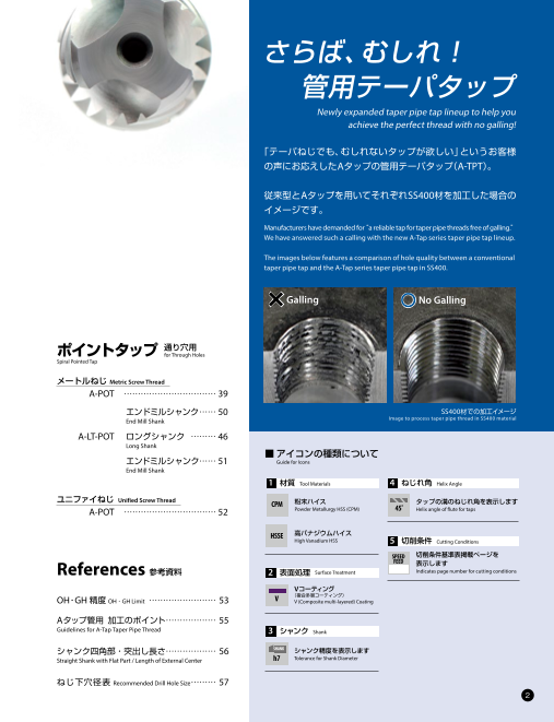
さらば、むしれ!
管用テーパタップ
Newly expanded taper pipe tap lineup to help you
achieve the perfect thread with no galling!
「テーパねじでも、むしれないタップが欲しい」というお客様
の声にお応えしたAタップの管用テーパタップ(A-TPT)。
従来型とAタップを用いてそれぞれSS400材を加工した場合の
イメージです。
Manufacturers have demanded for“ a reliable tap for taper pipe threads free of galling.”
We have answered such a calling with the new A-Tap series taper pipe tap lineup.
The images below features a comparison of hole quality between a conventional
taper pipe tap and the A-Tap series taper pipe tap in SS400.
×Galling ○No Galling
ポイントタップ 通り穴用for Through Holes
Spiral Pointed Tap
メートルねじ Metric Screw Thread
A-POT …………………………… 39
エンドミルシャンク …… 50 SS400材での加工イメージ
End Mill Shank Image to process taper pipe thread in SS400 material
A-LT-POT ロングシャンク ……… 46
Long Shank
■ アイコンの種類について
エンドミルシャンク…… 51 Guide for Icons
End Mill Shank
1 材質 Tool Materials 4 ねじれ角 Helix Angle
ユニファイねじ Unified Screw Thread CPM 粉末ハイス タップの溝のねじれ角を表示します
A-POT …………………………… 52 Powder Metallurgy HSS (CPM) 45˚ Helix angle of flute for taps
HSSE 高バナジウムハイス
High Vanadium HSS 5 切削条件 Cutting Conditions
SPEED 切削条件基準表掲載ページを
FEED
References 表示します
参考資料 2 表面処理 Surface Treatment Indicates page number for cutting conditions
Vコーティング
V (複合多層コーティング)
OH・GH精度 OH・GH Limit …………………… 53 V (Composite multi-layered) Coating
Aタップ管用 加工のポイント ……………… 55
Guidelines for A-Tap Taper Pipe Thread 3 シャンク Shank
シャンク四角部・突出し長さ……………… 56 SH ANK シャンク精度を表示します
Straight Shank with Flat Part / Length of External Center h7 Tolerance for Shank Diameter
ねじ下穴径表 Recommended Drill Hole Size ……… 57
2
Page4
特長(Features)
タップ加工に、困っていませんか?
Do you have any problems with tapping?
タップ加工の主なトラブル要因は、切りくず排出の不安定さです。Aタップシリーズは、
安定した切りくず排出性を持ち、さらに幅広い被削材や機械に対応できる画期的な製品です。
Most tapping troubles are caused by unstable chip evacuation. The A-Tap series resolves such troubles and is applicable to a wide range of
work materials and cutting conditions.
タップ加工のトラブル TOP3 Tapping Troubles
No.1 折損・欠け 主な
Breakage and chipping 26%
No.2 ねじ精度の不良 Dimensional error 17% トラブル要因は
“切りくず”
No.3 むしれ、かじり等 Galling 14% Main factor is chip packing
その他 Others 43%
当社コミュニケーションダイヤルへの相談実績より
Source: OSG Technical Consultation Division
Aタップなら、ここまでできる!
A-Tap takes it to another level.
切りくず形状を安定化
切れ味重視の ダントツの切りくず排出性! Chip Evacuation Redefined!
刃先仕様
[PAT. in Japan]
Sharp Cutting Edge
[PAT. in Japan]
Stabilizes chip shape
切りくず排出を促す
不等リード溝
[PAT. in Japan]
Variable Lead Flute
[PAT. in Japan]
Accelerate chip
evacuation
従来品 Conventional Tap A-SFT
高品位なめねじ加工 High-Grade Internal Threading
高い耐摩耗性
Vコーティング
V Coating むしれ・かじり無し
High wear resistance No Galling
高い耐摩耗性
粉末ハイス
Powder Metallurgy
HSS (CPM)
High wear resistance 被削材: 被削材:
SS400 SUS304
Work Material: Work Material:
Mild Steel Stainless Steel
3
Page5
幅広い切削領域 Comparison of Cutting Range
工具寿命 切削領域のイメージ図 Figure of Cutting Range
Tool Life
従来機 ※中・高炭素鋼(S45Cなど)を水溶性
長 同期送り機構付マシニングセンタ
CCoonnvveenttiionall
Long Machine Machining Center with Synchronized Feed and Rotation 切削油剤を使用して加工した場合の
Machine イメージです。
A ※切削速度15m/min以上の加工では、
タップ 同期送り機構付機械を推 奨します。
A-Tap
※最適速度は、使用条件により異なり
ます。試し加工により選定下さい。
コーティング付きタップ ※ Cutting range in medium and high
Coated Tap carbon steel with water-soluble coolant.
※ Machining center with synchronized
feed and rotation is recommended for
コーティング無しタップ more than 15m/min.
Non-Coated Tap ※ Results may vary based on cutting
condition. Please adjust speeds and
feeds accordingly.
5 10 20 30 40 50 75 100
切削速度(m/min)
Cutting Speed
加工設備を選ばない A-Tap is compatible with any type of machining equipment.
切削領域のイメージ図 00000000000000000000000
Aタップは手動式のボール盤
工具寿命 従来機 同期送り機構付マシニングセンタ
から最新のマシニングセンタ Tool Life Conventional Machinig Center with ynchronized Feed Mechanical
Machine
まで幅広い加工設備に対応。 長
Long Aシリーズ A series
マシニングセンタであれば、 A-POT / A-SFT
その性能をより発揮します。
コーティング付き
A-Tap is compatible with various types of machining タップ
equipment, from manual drilling machines to the Coating Taps
latest machining centers. A-Tap can maximize the
performance of any machining center. コーティング無し
タップ
Non-Coating Taps
5 10 20 30 40 50 75 100 切削速度
Tapping Speed
(m/min)
様々な被削材に対応 Applies to a wide variety of work materials
Aタップはステンレス、合金鋼など、様々な被削材に対応します。
A-Tap excels in a wide variety of materials, including stainless steels and alloy steels.
Aタップはオーエスジー株式会社の登録商標です。
4
参考資料 ポイントタップ Spiral Pointed Tap スパイラルタップ Spiral Fluted Tap 加工データ 切削条件 特長
References Cutting Data Cutting Conditions Features
U M インサート Insert 管用 Pipe U M
Page6
切削条件表(Cutting Conditions)
切削条件基準表 Cutting Conditions
■ A-SFT・A-LT-SFT( ~ M24、2.5P)
切削速度 (m/min)Cutting Speed 0 10 20 30 40 50 60 70
中・高炭素鋼
Medium Carbon Steel S45C 5-15 15-50 50-75
High Carbon Steel
合金鋼 SCM 5-10 10-15 15-30
Alloy Steel
一般構造用鋼 SS400 5-20(*)
Mild Steel
ステンレス鋼 SUS304 5-10 10-15
Stainless Steel SUS420
アルミニウム AC 5-50
Aluminum ADC
ダクタイル鋳鉄 FCD 5-50
Ductile Cast Iron
■A-SFT( ~ M24、ショートチャンファ1.5P・1P Short Chamfer)・A-SFT HL・A-LT-SFT HL
切削速度 (m/min)Cutting Speed 0 10 20 30 40 50 60 70
中・高炭素鋼
Medium Carbon Steel S45C 3-15 15-30
High Carbon Steel
合金鋼 SCM
Alloy Steel 3-8 (*)
一般構造用鋼 SS400 3-20(*)
Mild Steel
ステンレス鋼 SUS304 (*)
Stainless Steel SUS420 3-8
アルミニウム AC
ADC 3-30
Aluminum
ダクタイル鋳鉄 FCD 3-15
Ductile Cast Iron
■A-SFT( M27 ~、2.5P)・A-SFT(U)・A-SPT(G)
切削速度 (m/min)Cutting Speed 0 10 20 30 40 50 60 70
中・高炭素鋼
Medium Carbon Steel S45C 3-8 8-15
High Carbon Steel
合金鋼 SCM 3-8 8-15
Alloy Steel
一般構造用鋼 SS400 3-15(*)
Mild Steel
ステンレス鋼 SUS304
SUS420 3-8
Stainless Steel
アルミニウム AC 3-20
Aluminum ADC
ダクタイル鋳鉄 FCD 3-15
Ductile Cast Iron
■ A-SFT・A-LT-SFT( エンドミルシャンク End Mill Shank)
切削速度 (m/min)Cutting Speed 0 10 20 30 40 50 60 70
中・高炭素鋼
Medium Carbon Steel S45C 5-15 15-50 50-75
High Carbon Steel
合金鋼 SCM
Alloy Steel 5-10 10-15 15-30
一般構造用鋼 SS400 5-20(*)
Mild Steel
ステンレス鋼 SUS304 5-10 10-15
Stainless Steel SUS420
アルミニウム AC 5-50
Aluminum ADC
ダクタイル鋳鉄 FCD 5-75
Ductile Cast Iron
推奨領域 加工可能領域
Advisable Possible
5
Page7
切削条件基準表 Cutting Conditions
■A -TPT・A-S-TPT・A-SPT(Rp・NPS)
切削速度 (m/min)Cutting Speed 0 10 20 30 40 50 60 70
中・高炭素鋼
Medium Carbon Steel S45C 2-5 5-10
High Carbon Steel
合金鋼 SCM
Alloy Steel 2-5(*)
一般構造用鋼 SS400 2-5 5-10
Mild Steel
ステンレス鋼 SUS304 2-5
Stainless Steel SUS420
アルミニウム AC
ADC 2-5 5-10
Aluminum
ダクタイル鋳鉄 FCD
Ductile Cast Iron 2-5
■ A-POT・A-LT-POT
切削速度 (m/min)Cutting Speed 0 10 20 30 40 50 60 70
中・高炭素鋼
Medium Carbon Steel S45C 5-15 15-50 50-75
High Carbon Steel
合金鋼 SCM 5-10 10-30 30-50
Alloy Steel
一般構造用鋼 SS400 5-15 15-50
Mild Steel 50-75
ステンレス鋼 SUS304
SUS420 5-15 15-30
Stainless Steel
アルミニウム AC
Aluminum ADC 5-50
ダクタイル鋳鉄 FCD 5-50
Ductile Cast Iron
■ A-POT・A-LT-POT( エンドミルシャンク End Mill Shank)
切削速度 (m/min)Cutting Speed 0 10 20 30 40 50 60 70
中・高炭素鋼
Medium Carbon Steel S45C 5-15 15-75
High Carbon Steel
合金鋼 SCM 5-10 10-30 30-50
Alloy Steel
一般構造用鋼 SS400 5-15 15-50 50-75
Mild Steel
ステンレス鋼 SUS304 5-15 15-30
Stainless Steel SUS420
アルミニウム AC 5-50
Aluminum ADC
ダクタイル鋳鉄 FCD 5-75
Ductile Cast Iron
推奨領域 加工可能領域
Advisable Possible
1. 切削速度は、実際の加工状態を確認した上で選定下さい。 1. Cutting speed should be adjusted according to the machining conditions.
2. この切削条件基準表は、水溶性切削油剤を使用する場合のものです。 2. The indicated speeds and feeds are for tapping with water-soluble oil.
3. 切削油剤の状態により、十分な性能が発揮できない場合があります。 3. Depending on the coolant condition, it may not show a good results.
4. エンドミルシャンク品はコレットホルダ、ミーリングホルダなどに対応して 4. Although taps with end mill shank are compatible with a collet holder,
いますが、まわり止め付きホルダをご使用下さい。 milling holder and etc., use a holder with a detent.
(*)加工領域にご注意下さい。 (*)Please set cutting speed carefully.
6
参考資料 ポイントタップ Spiral Pointed Tap スパイラルタップ Spiral Fluted Tap 加工データ 切削条件 特長
References Cutting Data Cutting Conditions Features
U M インサート Insert 管用 Pipe U M
Page8
加工データ(Cutting Data)
加工データ Cutting Data
■ 切削速度と切りくず形状 Cutting speed and shape of chips
使用工具 A-SFT M8×1.25 2.5P 切削速度 Cutting Speed
Tool
5m/min 10m/min 15m/min
被削材
Work Material S45C
下穴 φ6.8×18mm(止り)
Drill Hole Size Blind
ねじ立て長さ
Tapping Length 12mm( 1.5D) 30m/min 50m/min 75m/min
切削油剤 水溶性切削油剤 塩素フリー10倍
Coolant Water-Soluble Chlorine-Free (10%)
使用機械 立形マシニングセンタ(同期送り機構付き)
Machine Vertical Synchronized Machining Center
・ 切削速度を変えても切りくず形状が安定している ・ The shape of chips is stable even if the tapping speed is high.
・ 切削速度10m /min以下でも切りくず形状は安定 ・ Shape of chips is stable even if the tapping speed is 10m/min or
していますが、高速切削することにより遠心力が less; however, separation of chip would improve tremendously 推奨条件
増して、タップからの切りくず離れが向上します by increasing the speed and centrifugal force. Recommended Speed
■ 切削速度と安定性 Cutting speed and performance stability
使用工具
Tool A-SFT M6×1 2.5P 加工穴数 Tapping Holes
500 1,000 1,500
被削材
Work Material S45C
下穴 φ5×16mm(止り)
Drill Hole Size Blind 15m/min 1,400穴 Holes 継続可
Still Running
ねじ立て長さ
Tapping Length 12mm( 2D)
切削油剤 水溶性切削油剤 塩素フリー10倍
Coolant Water-Soluble Chlorine-Free (10%) 継続可
使用機械 立形マシニングセンタ(同期送り機構付き) 30m/min 1,400穴 Holes Still Running
Machine Vertical Synchronized Machining Center
■40m/min切削時の切りくず Chip generated in 40m/min
40m/min 1,400穴 継続可
Holes
Still Running
15、30、40m/minそれぞれの速度で結果にばらつきはなく、安定加工が可能
A-SFT 従来品 Conventional Tap The results of tapping operations in 15, 30, 40m/min are all stable.
■ マシニングセンタの能力を活かす切削領域でも性能を発揮 A-POT maximizes the performance of machining center
使用工具
Tool A-POT M8×1.25 加工穴数 Tapping Holes
1,000 2,000 3,000 4,000 5,000
被削材
Work Material S50C
下穴 φ6.8×16mm(通り) A-POT 4,947穴 Holes 損傷大
Drill Hole Size Through Large Wear
ねじ立て長さ
Tapping Length 16mm( 2D) 従来品 3,816穴 折損
Holes
Conventional Breakage
切削速度 -1
Cutting Speed 30m/min( 1,190min )
他社品 2,865穴 Holes GP-Out
切削油剤 水溶性切削油剤 塩素フリー10倍 Competitor
Coolant Water-Soluble Chlorine-Free (10%)
使用機械 横形マシニングセンタ(同期送り機構付き) 他社品や従来品との性能差を確認
Machine Horizontal Synchronized Machining Center The advantage of A-POT over the competitors’ and conventional taps was verified.
7
Page9
加工データ Cutting Data
■ S45C通り穴の高速加工 High speed machining of S45C( Through)
使用工具
Tool A-POT 従来品 加工穴数 Tapping Holes
Conventional Tap
1,000 2,000 3,000 4,000 5,000 6,000 7,000
サイズ
Size M8×1.25
被削材
Work Material S45C A-POT 6,501穴 Holes GP-Out
下穴 φ6.8×16mm(通り)
Drill Hole Size Through
ねじ立て長さ
Tapping Length 16mm( 2D)
切削速度 従来品
-1 4,553穴 Holes GP-Out
Cutting Speed 50m/min( 1,990min ) Conventional
切削油剤 水溶性切削油剤 塩素フリー10倍
Coolant Water-Soluble Chlorine-Free (10%)
使用機械 立形マシニングセンタ(同期送り機構付き) A-POT(エンドミルシャンク)は従来品に対して約1.5倍の耐久性
Machine Vertical Synchronized Machining Center A-POT (End Mill Shank) has achieved 1.5 times of durability versus conventional tool.
■ 十分な安定給油でMQLでも加工可能 MQL possible with su cient and stable coolant supply
使用工具
Tool A-SFT M8×1.25 2.5P ■500穴加工後 Cutting edge after tapping 500 hole
被削材
Work Material S45C AC4C-F
下穴 φ6.8×24mm(止り)
Drill Hole Size Blind
ねじ立て長さ
Tapping Length 16mm( 2D)
切削速度
Cutting Speed 30m/min( 1,194min-1)
切削油剤 MQL 50cc/h(内部給油)
Coolant (Internal)
使用機械 横形マシニングセンタ(同期送り機構付き)
Machine Horizontal Synchronized Machining Center
S45C AC4C-F
センタースルー Center through coolant hole 500穴加工後も大きな損傷なし
No significant damage was found even after tapping 500 holes.
8
参考資料 ポイントタップ Spiral Pointed Tap スパイラルタップ Spiral Fluted Tap 加工データ 切削条件 特長
References Cutting Data Cutting Conditions Features
U M インサート Insert 管用 Pipe U M
Page10
加工データ Cutting Data
■ 大径の加工 Threading in large hole
使用工具
Tool A-SFT M36×4 2.5P
被削材
Work Material SS400 SUS304
下穴 φ32×70mm(止り)
Drill Hole Size Blind
ねじ立て長さ
Tapping Length 54mm( 1.5D)
切削速度 -1
Cutting Speed 7m/min( 62min )
切削油剤 水溶性切削油剤 塩素フリー20倍
Coolant Water-Soluble Chlorine-Free (5%) 従来品 Conventional Tap A-SFT
使用機械 横形マシニングセンタ ※めねじの加工イメージであり、仕上がりは加工状況により異なります
Machine Horizontal Machining Center Visual reference of internal threads. Result may differ based on actual machining condition.
従来めねじのむしれが問題となるSS400やSUS材も 従来品 Conventional Tap A-SFT
水溶性油剤で加工可能
The use of water-soluble coolant is possible even in
difficult-to-machine materials such as SS400 and stainless ×Galling No Galling
steels, which could not be achieved by conventional taps. ○
×Galling ○No Galling
■ 食付き部の長さと耐久数 Chamfer length & durability
使用工具 A-SFT M6×1 加工穴数 Tapping Holes
Tool
500 1,000 1,500 2,000 2,500
被削材
Work Material S45C
下穴 φ5×16mm(止り) 継続可
Drill Hole Size Blind 2.5P 2,200穴 Holes Still Running
ねじ立て長さ
Tapping Length 12mm( 2D)
切削速度 -1
Cutting Speed 15m/min( 796min )
切削油剤 水溶性切削油剤 塩素フリー10倍 1.5P 1,109穴 折損
Holes
Coolant Water-Soluble Chlorine-Free (10%) Breakage
使用機械 立形マシニングセンタ
Machine Vertical Machining Center
食付き1.5P品も1,000穴以上を加工可能 他社品1.5P 126穴 Holes WP-Out
The machining of over 1,000 holes is possible even with 1.5 Competitor
chamfer length.
9
SUS304 SS400
Page11
加工データ Cutting Data
■ 小径の加工 Threading in small hole
使用工具
Tool A-SFT M2×0.4 2.5P
被削材
Work Material SUS304 S45C
下穴 φ1.6×4.5mm(止り)
Drill Hole Size Blind
ねじ立て長さ
Tapping Length 3mm( 1.5D)
切削速度
Cutting Speed 5m/min( 800min-1) 10m/min( 1,600min-1) 30m/min( 4,800min-1)
切削油剤 水溶性切削油剤 塩素フリー10倍
Coolant Water-Soluble Chlorine-Free (10%)
使用機械 立形マシニングセンタ(同期送り機構付き)
Machine Vertical Synchronized Machining Center
■100穴加工後 Cutting edge after tapping 100 hole
SUS304 5m/min S45C 10m/min S45C 30m/min
1本でSUS304とS45Cを安定加工可能
A single tap for stable machining in SUS304 and S45C.
■ SUS304の2D深穴加工 Deep hole tapping (2D) in stainless steel
使用工具
Tool A-SFT M8×1.25 2.5P 加工穴数 Tapping Holes
400 800 1,200
被削材
Work Material SUS304
下穴 φ6.8×22mm(止り)
Drill Hole Size Blind A-SFT 1,000穴 継続可
Holes Still Running
ねじ立て長さ
Tapping Length 16mm( 2D)
切削速度 -1
Cutting Speed 10m/min( 398min )
切削油剤 水溶性切削油剤 塩素フリー10倍 他社品 57穴 折損
Holes
Coolant Water-Soluble Chlorine-Free (10%) Competitor Breakage
使用機械 立形マシニングセンタ(同期送り機構付き)
Machine Vertical Synchronized Machining Center
ステンレスの水溶性加工でも抜群の性能 ■1,000穴加工後 Cutting edge after tapping 1,000 holes
High performance achieved in stainless steel with
water-soluble coolant.
10
参考資料 ポイントタップ Spiral Pointed Tap スパイラルタップ Spiral Fluted Tap 加工データ 切削条件 特長
References Cutting Data Cutting Conditions Features
U M インサート Insert 管用 Pipe U M
Page12
加工データ Cutting Data
■ 管用テーパの加工 Processing of taper pipe threads
使用工具
Tool A-TPT PT 1⁄8-28 2.5P
被削材
Work Material SS400 FCD400 SUS304
下穴 φ8.2×16mm(通り)
Drill Hole Size Through
基準径位置
Position of Gauge Plane 13mm
切削速度 -1
Cutting Speed 5m/min( 164min )
切削油剤 水溶性切削油剤 塩素フリー10倍
Coolant Water-Soluble Chlorine-Free (10%)
使用機械 立形マシニングセンタ(BT30)
Machine Vertical Machining Center
SS400 FCD400 SUS304
3材種ともに100穴加工後の損傷は小さく、継続使用が可能であった。
The taper pipe tap was observed with minimal wear and can continue to be used even after tapping 100 holes in three different work materials.
■ 管用テーパの加工 Processing with taper pipe taps
使用工具
Tool A-TPT PT 1⁄8-28 2.5P 加工穴数 Tapping Holes
20 40 60 80 100
被削材
Work Material SS400
下穴 φ8.2×16mm(通り)
Drill Hole Size Through A-TPT 100 継続可能
穴 Holes Still Running
基準径位置
Position of Gauge Plane 13mm
切削速度 -1
Cutting Speed 7m/min( 230min )
切削油剤 水溶性切削油剤 塩素フリー10倍 他社品 0穴 めねじむしれ大
Hole
Coolant Water-Soluble Chlorine-Free (10%) Competitor Galling
使用機械 横形マシニングセンタ
Machine Horizontal Machining Center
他社品が加工不可な状況でも安定加工が可能!
Stable performance can be achieved even under
conditions where the competitor's tool failed to process a
single hole.
A-TPT 他社品 Competitor
11
Page13
加工データ Cutting Data
■ 15-5PHの加工 Tapping in 15-5PH
使用工具
Tool A-SFT HL No.10-32UNF 加工穴数 Tapping Holes
20 40 60 80 100
被削材
Work Material 15-5PH H1025 40HRC / AMS5659
下穴 φ5×16mm(止り)
Drill Hole Size Blind A-SFT HL 100穴 継続可能
Holes Still Running
ねじ立て長さ
Tapping Length 10mm
切削速度 -1
Cutting Speed 5m/min( 275min )
切削油剤 水溶性切削油剤 塩素フリー10倍
Coolant Water-Soluble Chlorine-Free (10%)
使用機械 立形マシニングセンタ(同期送り機構付き)
Machine Vertical Synchronized Machining Center
航空機用材料も安定加工が可能!
Stable processing is possible even in advanced materials
for aircraft!
切りくず Cutting Chips 100穴加工後 Cutting edge after tapping 100 holes
■ 同期送り機構付きマシニングセンタの効果 Bene
t of machining center with synchronized feed and rotation
使用工具 A-SFT M6×1 2.5P 加工穴数 Tapping Holes
Tool
500 1,000 1,500 2,000 2,500 3,000
被削材
Work Material S45C
下穴 φ5×16mm(止り) A-SFT
Drill Hole Size Blind 同期送り 2,798穴 Holes 摩耗
ねじ立て長さ Synchronized Wear
12mm( 2D) Machining
Tapping Length
切削速度
Cutting Speed 15m/min( 796min-1)
A-SFT
切削油剤 水溶性切削油剤 塩素フリー10倍 フローティング式 1,726穴 Holes 摩耗
Wear
Coolant Water-Soluble Chlorine-Free (10%) Floating Holder
使用機械 立形マシニングセンタ
Machine Vertical Machining Center
従来機でも1,700穴以上の加工が可能だが、同期送りを使用することで更なる耐久UPが
可能となった。
Over 1,700 holes can be processed by using a conventional machining center, but performance
can be further improved by using machining with synchronized feed and rotation.
12
参考資料 ポイントタップ Spiral Pointed Tap スパイラルタップ Spiral Fluted Tap 加工データ 切削条件 特長
References Cutting Data Cutting Conditions Features
U M インサート Insert 管用 Pipe U M
Page14
加工データ Cutting Data
■ タップの耐久は下穴加工で決まる! The tool life of a tap is determined by the drill used before tapping process!
使用工具 異なる2種類のドリルで下穴をあけ、その後、A-POTでタップ加工を行った。
Tool A-POT M10×1.5 ADO-SUSでの下穴加工をすることにより、タップの耐久差は最大で1,570穴になった。
ねじ立て長さ 19mm( 通り) Two different drills were used before tapping process! Result demonstrates that with the use of
Tapping Length Through ADO-SUS, tool life of A-POT can be extended by as many as 1,570 holes.
切削速度
Cutting Speed 20m/min( 637min-1)
被削材
Work Material SUS304
切削油剤 水溶性切削油剤 塩素フリー10倍 *下穴加工ドリルはともに3D、φ8.5、 穴深さ19mm(通り穴)
Coolant Water-Soluble Chlorine-Free (10%) *Drills: 3D, φ8.5, Depth of Hole 19mm (Through)
ADO-SUSドリル : 70m/min (2,630min-1 ), 526mm/min (0.2mm/rev)
使用機械 横形マシニングセンタ(同期送り機構付き)
Machine Horizontal Synchronized Machining Center 他社超硬ドリル : 60m/min (2,250min-1), 450mm/min (0.2mm/rev)
Competitor's Carbide Drill
■ タップ損傷状態
■下穴加工ドリル別タップ加工穴数の違い (3,500穴加工時)
Di
erence in the number of tapped holes based on drill type used prior to threading Wear on cutting edge after tapping 3,500 holes
下穴に使用したドリル 加工穴数 Tapping Holes
Drill used befor tapping 3,000 4,000 5,000 6,000
ADO-SUS 5,495穴 Holes 摩耗 ADO-SUS使用
Wear Drilled by ADO-SUS
1,570穴差
他社超硬ドリル 3,925穴 Holes 折損 Difference of 1,570 holes
Competitor's Carbide Drill Breakage
他社超硬ドリル使用
Drilled by Competitor's Carbide Drill
A-Drillのココがすごい! The A-Drill SUS・TI用 超硬ドリル
Advantage ADO Carbide Drill for SUS・TI ADO-SUS
ADO-SUSは新型オイルホール形状
“MEGA COOLER”採用で、
By adopting the new oil hole shape“ MEGA COOLER,”
coolant flow velocity can be increased by 120%
切削油剤供給量
Feed Rate of Coolant
120%
PAT. in Japan
通常形状
Oil Hole MEGA COOLERはオーエスジー株式会社の登録商標です。
MEGA COOLER is a registered trademark of OSG Corporation.
13
Page15
加工データ Cutting Data
■ タップの耐久は下穴加工で決まる! The tool life of a tap is determined by the drill used before tapping process!
使用工具 他社汎用超硬ドリルで加工すると抜けばりが大きいためタップの耐久が不安定に
Tool A-POT M10×1.5 なる。一方、ADFで加工するとタップの耐久は安定した。
ねじ立て長さ 20mm( 通り) With the use of a competitor's carbide general-purpose drill, large burrs were left resulting
Tapping Length Through in instability of the after tapping process. With the ADF, on the other hand, stable tapping
performance can be achieved.
切削速度 -1
Cutting Speed 30m/min( 955min )
被削材
Work Material SS400
切削油剤 水溶性切削油剤 塩素フリー10倍
Coolant Water-Soluble Chlorine-Free (10%)
*下穴加工ドリルはともに、φ8.5、 穴深さ20mm(通り穴)
使用機械 横形マシニングセンタ(同期送り機構付き) *Drills: φ8.5, Depth of Hole 20mm (Through)
Machine Horizontal Synchronized Machining Center 50m/min (1,873min-1 ), 318mm/min (0.17mm/rev)
■使用ドリル別刃先と抜け面の比較 Damage comparison based on drill type used prior to threading ■加工モデル図 Application
損傷状態 ADF 使用 他社汎用超硬ドリル使用
State of Damage Drilled by ADF Drilled by Competitor's General Carbide Drill
刃先
(200穴タップ加工時)
Wear on cutting edge
after tapping 200 holes
継続可能 Still Running 刃欠け大 Chipping 30°
抜け面
Hole Exit
A-Drillのココがすごい! The A-Drill 超硬フラットドリル
Advantage Carbide Flat Drill ADF
ADFは底刃形状をフラットにすることで、 切削抵抗、スラスト力が一方向に
With a flat cutting edge geometry, 集中するため安定加工が実現。
cutting resistance can be reduced with thrust force concentrated in
one direction, enabling stable machining.
汎用ドリル General Drills ADF( 先端フラット)
ADF (flat cutting edge)
14
参考資料 ポイントタップ Spiral Pointed Tap スパイラルタップ Spiral Fluted Tap 加工データ 切削条件 特長
References Cutting Data Cutting Conditions Features
U M インサート Insert 管用 Pipe U M
Page16
スパイラルタップ(Spiral Fluted Tap)、A-SFT
スパイラルタップ Spiral Fluted Tap
A-SFT
ℓc
THLGTH ℓk S
LU RV
■ 食付き部の長さ(ℓc)2.5P、1.5P、1P D
Chamfer Length LF
■ 全サイズねじ側突出しセンタ除去品です
The entire lineup of A-SFT is without external center on the screw side.
SPEED
CPM FEED
V 45˚ P5
ねじの種類:M 単位 :mm Unit:mm
ツールNo. 呼び 精度表記 精度 食付 全長 ねじ部の長さ 首下の長さ シャンク径 溝数 推奨下穴径 在庫 標準価格
EDP No. Thread Size Grade TAP Limit ℓc LF THLGTH LU DCON NOF Recommended
drill hole dia. Stock (Yen)
8325234 M 1.4 × 0.3 STD OH1 2.5P 34 6 - 3 2 1.1 D ● 4,590
8325239 M 1.6 × 0.35 STD OH1.5 2.5P 36 7 - 3 2 1.25 D ● 4,590
8325244 M 1.7 × 0.35 STD OH1.5 2.5P 36 8 - 3 2 1.35 D ● 4,270
8325249 STD OH1.5 A ● 3,590
8325630 STD+1 OH2.5 2.5P ● 3,940
M 2 × 0.4 40 3.2 10 3 2 1.6
8325631 STD+2 OH3.5 D ● 3,940
8327449 STD OH1.5 1.5P ● 4,120
8325250 STD OH1 ● 5,340
2.5P
8325632 M 2 × 0.25 STD+1 OH2 40 3.2 10 3 2 1.75 D ● 5,590
8327450 STD OH1 1.5P ● 5,880
8325252 STD OH2 ● 4,140
2.5P
8325634 M 2.2 × 0.45 STD+1 OH3 42 3.6 11 3 2 1.75 D ● 4,350
8327452 STD OH2 1.5P ● 4,560
8325253 STD OH1 ● 5,980
2.5P
8325636 M 2.2 × 0.25 STD+1 OH2 42 3.6 11 3 2 1.95 D ● 6,270
8327453 STD OH1 1.5P ● 6,570
8325254 STD OH1.5 B ● 3,370
2.5P
8325638 M 2.3 × 0.4 STD+1 OH2.5 42 3.6 12 3 2 1.9 ● 3,730
D
8327454 STD OH1.5 1.5P ● 3,870
8325259 STD OH2 B ● 3,160
8325640 STD+1 OH3 2.5P ● 3,470
M 2.5 × 0.45 44 3.6 13 3 2 2.05
8325641 STD+2 OH4 D ● 3,470
8327459 STD OH2 1.5P ● 3,620
8325262 STD OH1.5 ● 4,530
2.5P
8325642 M 2.5 × 0.35 STD+1 OH2.5 44 3.6 13 3 2 2.15 D ● 4,770
8327462 STD OH1.5 1.5P ● 4,980
8325264 STD OH2 A ● 2,960
2.5P
8325644 M 2.6 × 0.45 STD+1 OH3 44 3.6 13 3 2 2.15 ● 3,240
D
8327464 STD OH2 1.5P ● 3,390
●=標準在庫品 ●=Standard stock item
FROM NEXT
15
DCON
Page17
スパイラルタップ Spiral Fluted Tap
ここがいいね !
Key Point
A-SFTは全サイズねじ側突出しセンタ除去品ですので、
下穴深さに余裕がない加工にも最適です。
The entire lineup of A-SFT is without external center on the screw side,
which is ideal for applications with tight clearance at the bottom of the hole.
FROM NEXT 単位 :mm Unit:mm
ツールNo. 呼び 精度表記 精度 食付 全長 ねじ部の長さ 首下の長さ シャンク径 溝数 推奨下穴径 在庫 標準価格
EDP No. Thread Size Grade TAP Limit ℓc LF THLGTH LU DCON NOF Recommended
drill hole dia. Stock (Yen)
8325269 STD OH2 A ● 2,500
8325650 STD+1 OH3 2.5P ● 2,740
D
8325651 M 3 × 0.5 STD+2 OH4 46 4 19 4 3 2.5 ● 2,740
8326711 STD OH2 1.5P B ● 2,770
8326811 STD OH2 1P D ● 2,900
8325272 STD OH2 ● 3,680
2.5P
8325652 M 3 × 0.35 STD+1 OH3 46 4 19 4 3 2.65 D ● 3,890
8327472 STD OH2 1.5P ● 4,040
8325276 STD OH2 B ● 2,790
2.5P
8325654 M 3.5 × 0.6 STD+1 OH3 48 4.8 20 4 3 2.9 ● 3,130
D
8327476 STD OH2 1.5P ● 3,220
8325279 STD OH2 ● 4,140
2.5P
8325655 M 3.5 × 0.35 STD+1 OH3 48 4.8 20 4 3 3.15 D ● 4,370
8327479 STD OH2 1.5P ● 4,560
8325283 STD OH3 A ● 2,470
8325660 STD+1 OH4 2.5P ● 2,690
D
8325661 M 4 × 0.7 STD+2 OH5 52 5.6 21 5 3 3.3 ● 2,690
8326714 STD OH3 1.5P B ● 2,700
8326814 STD OH3 1P D ● 2,820
8325286 STD OH2 ● 3,220
2.5P
8325662 M 4 × 0.5 STD+1 OH3 52 5.6 21 5 3 3.5 D ● 3,370
8327486 STD OH2 1.5P ● 3,520
●=標準在庫品 ●=Standard stock item
■ アイコンの説明はp.2をご覧下さい。 ■ See p.2 for explanation of icons.
■ シャンク四角部寸法ℓk, DRVSはp.56をご覧下さい。 ■ See p.56 for shank square length(ℓk) and width(DRVS).
1. 精度欄■は2級めねじ相当適応のタップ推奨精度です。 1. The recommended tap limit corresponds to JIS class 2 internal thread standard.
2. タップ精度はめねじ精度を保証するものではありません。 2. Tap limit does not guarantee thread limit for the internal thread after tapping.
3. 送りの不安定な機械で使用しますと、めねじ拡大トラブルが発生する場合があります 3. Stable feed control machines are recommended to avoid over size tapping.
のでご注意下さい。 4. Regrinding is not recommended.
4. 再研磨はお勧めしておりません。 5. The recommended tap limit corresponds to JIS class 2 internal thread standard.
5. 推奨下穴径は、旧 JIS2級めねじ用です。(旧 JISの規格にないめねじは除く) The recommended drill hole size that are not listed on JIS is as reference.
JIS規格にないめねじの下穴径は、参考値です。
FROM NEXT
16
参考資料 ポイントタップ Spiral Pointed Tap スパイラルタップ Spiral Fluted Tap 加工データ 切削条件 特長
References Cutting Data Cutting Conditions Features
U M インサート Insert 管用 Pipe U M
Page18
スパイラルタップ Spiral Fluted Tap
A-SFT
ℓc
THLGTH ℓk VS
LU R
■ 食付き部の長さ(ℓc)2.5P、1.5P、1P D
Chamfer Length LF
■ 全サイズねじ側突出しセンタ除去品です
The entire lineup of A-SFT is without external center on the screw side.
SPEED
CPM FEED
V 45˚ P5
FROM NEXT
ねじの種類:M 単位 :mm Unit:mm
ツールNo. 呼び 精度表記 精度 食付 全長 ねじ部の長さ 首下の長さ シャンク径 溝数 推奨下穴径 在庫 標準価格
EDP No. Thread Size Grade TAP Limit ℓc LF THLGTH LU DCON NOF Recommended
drill hole dia. Stock (Yen)
8325287 STD OH2 ● 3,160
2.5P
8325664 M 4.5 × 0.75 STD+1 OH3 55 6 21 5 3 3.8 D ● 3,320
8327487 STD OH2 1.5P ● 3,470
8325288 STD OH2 ● 3,730
2.5P
8325665 M 4.5 × 0.5 STD+1 OH3 55 6 21 5 3 4 D ● 3,910
8327488 STD OH2 1.5P ● 4,100
8325290 STD OH3 A ● 2,480
8325668 STD+1 OH4 2.5P ● 2,710
D
8325669 M 5 × 0.8 STD+2 OH5 60 6.4 24 5.5 3 4.2 ● 2,710
8326717 STD OH3 1.5P B ● 2,720
8326817 STD OH3 1P D ● 2,850
8325293 STD OH2 ● 3,350
2.5P
8325673 M 5 × 0.5 STD+1 OH3 60 6.4 24 5.5 3 4.5 D ● 3,500
8327493 STD OH2 1.5P ● 3,680
8325295 STD OH2 ● 3,890
2.5P
8325676 M 5.5 × 0.5 STD+1 OH3 60 7.2 25 5.5 3 5 D ● 4,070
8327495 STD OH2 1.5P ● 4,270
8325297 STD OH3 A ● 2,550
8325678 STD+1 OH4 2.5P ● 2,800
D
8325679 M 6 × 1 STD+2 OH5 62 8 29 6 3 5 ● 2,800
8326720 STD OH3 1.5P B ● 2,810
8326820 STD OH3 1P D ● 2,940
8325300 STD OH2 B ● 3,190
2.5P
8325680 M 6 × 0.75 STD+1 OH3 62 8 29 6 3 5.3 ● 3,500
D
8327500 STD OH2 1.5P ● 3,680
●=標準在庫品 ●=Standard stock item
FROM NEXT
17
DCON
Page19
スパイラルタップ Spiral Fluted Tap
ここがいいね !
Key Point
A-SFTは全サイズねじ側突出しセンタ除去品ですので、
下穴深さに余裕がない加工にも最適です。
The entire lineup of A-SFT is without external center on the screw side,
which is ideal for applications with tight clearance at the bottom of the hole.
FROM NEXT 単位 :mm Unit:mm
ツールNo. 呼び 精度表記 精度 食付 全長 ねじ部の長さ 首下の長さ シャンク径 溝数 推奨下穴径 在庫 標準価格
EDP No. Thread Size Grade TAP Limit ℓc LF THLGTH LU DCON NOF Recommended
drill hole dia. Stock (Yen)
8325302 STD OH2 ● 3,730
2.5P
8325681 M 6 × 0.5 STD+1 OH3 62 8 29 6 3 5.5 D ● 3,910
8327502 STD OH2 1.5P ● 4,100
8325304 STD OH3 ● 3,580
2.5P
8325684 M 7 × 1 STD+1 OH4 65 12 33 6.2 3 6 D ● 3,800
8327504 STD OH3 1.5P ● 3,940
8325305 STD OH2 ● 4,310
2.5P
8325685 M 7 × 0.75 STD+1 OH3 65 9 33 6.2 3 6.3 D ● 4,500
8327505 STD OH2 1.5P ● 4,730
8325307 STD OH3 A ● 3,330
8325688 STD+1 OH4 2.5P ● 3,650
D
8325689 M 8 × 1.25 STD+2 OH5 70 15 37 6.2 3 6.8 ● 3,650
8326723 STD OH3 1.5P B ● 3,660
8326823 STD OH3 1P D ● 3,830
8325311 STD OH3 B ● 3,930
2.5P
8325690 M 8 × 1 STD+1 OH4 70 12 37 6.2 3 7 ● 4,330
D
8327511 STD OH3 1.5P ● 4,530
8325312 STD OH3 ● 4,500
2.5P
8325691 M 8 × 0.75 STD+1 OH4 70 12 37 6.2 3 7.3 D ● 4,710
8327512 STD OH3 1.5P ● 4,940
8325314 STD OH3 ● 4,250
2.5P
8325694 M 9 × 1.25 STD+1 OH4 72 15 38 7 3 7.8 D ● 4,480
8327514 STD OH3 1.5P ● 4,670
●=標準在庫品 ●=Standard stock item
■ アイコンの説明はp.2をご覧下さい。 ■ See p.2 for explanation of icons.
■ シャンク四角部寸法ℓk, DRVSはp.56をご覧下さい。 ■ See p.56 for shank square length(ℓk) and width(DRVS).
1. 精度欄■は2級めねじ相当適応のタップ推奨精度です。 1. The recommended tap limit corresponds to JIS class 2 internal thread standard.
2. タップ精度はめねじ精度を保証するものではありません。 2. Tap limit does not guarantee thread limit for the internal thread after tapping.
3. 送りの不安定な機械で使用しますと、めねじ拡大トラブルが発生する場合があります 3. Stable feed control machines are recommended to avoid over size tapping.
のでご注意下さい。 4. Regrinding is not recommended.
4. 再研磨はお勧めしておりません。 5. The recommended tap limit corresponds to JIS class 2 internal thread standard.
5. 推奨下穴径は、旧 JIS2級めねじ用です。(旧 JISの規格にないめねじは除く) The recommended drill hole size that are not listed on JIS is as reference.
JIS規格にないめねじの下穴径は、参考値です。
FROM NEXT
18
参考資料 ポイントタップ Spiral Pointed Tap スパイラルタップ Spiral Fluted Tap 加工データ 切削条件 特長
References Cutting Data Cutting Conditions Features
U M インサート Insert 管用 Pipe U M
Page20
スパイラルタップ Spiral Fluted Tap
A-SFT
ℓc
THLGTH ℓk VS
LU R
■ 食付き部の長さ(ℓc)2.5P、1.5P、1P D
Chamfer Length LF
■ 全サイズねじ側突出しセンタ除去品です
The entire lineup of A-SFT is without external center on the screw side.
SPEED
CPM FEED
V 45˚ P5
FROM NEXT
ねじの種類:M 単位 :mm Unit:mm
ツールNo. 呼び 精度表記 精度 食付 全長 ねじ部の長さ 首下の長さ シャンク径 溝数 推奨下穴径 在庫 標準価格
EDP No. Thread Size Grade TAP Limit ℓc LF THLGTH LU DCON NOF Recommended
drill hole dia. Stock (Yen)
8325315 STD OH3 ● 5,000
2.5P
8325695 M 9 × 1 STD+1 OH4 72 12 38 7 3 8 D ● 5,250
8327515 STD OH3 1.5P ● 5,520
8325316 STD OH3 ● 5,440
2.5P
8325696 M 9 × 0.75 STD+1 OH4 72 12 38 7 3 8.3 D ● 5,700
8327516 STD OH3 1.5P ● 5,980
8325317 STD OH3 A ● 4,030
8325700 STD+1 OH4 2.5P ● 4,440
D
8325701 M 10 × 1.5 STD+2 OH5 75 18 41 7 3 8.5 ● 4,440
8326726 STD OH3 1.5P B ● 4,450
8326826 STD OH3 1P D ● 4,670
8325321 STD OH3 A ● 4,030
2.5P
8325702 STD+1 OH4 D ● 4,440
M 10 × 1.25 75 15 41 7 3 8.8
8326729 STD OH3 1.5P B ● 4,450
8326829 STD OH3 1P D ● 4,670
8325324 STD OH3 B ● 4,780
2.5P
8325703 M 10 × 1 STD+1 OH4 75 15 41 7 3 9 ● 5,250
D
8327524 STD OH3 1.5P ● 5,520
8325325 STD OH3 ● 5,570
2.5P
8325704 M 10 × 0.75 STD+1 OH4 75 15 41 7 3 9.3 D ● 5,700
8327525 STD OH3 1.5P ● 6,120
8325327 STD OH3 ● 5,230
2.5P
8325710 M 11 × 1.5 STD+1 OH4 80 18 48 8 3 9.5 D ● 5,480
8327527 STD OH3 1.5P ● 5,760
●=標準在庫品 ●=Standard stock item
FROM NEXT
19
DCON