GF Piping Systems
- System Specification -
for SYGEF Standard Piping Systems in Polyvinylidene fluoride (PVDF)
1. Scope
This specification covers requirements for the GF SYGEF Standard (PVDF) Piping
System intended for a wide range of applications including water, wastewater and
effluent treatment as well as a wide range of chemical applications. The components
of the SYGEF Standard (PVDF) piping systems are in accordance with the following
standards.
2. Basic System Data
2.1 Material Specification for SYGEF Standard (PVDF)
SYGEF Standard (PVDF) pipes, fittings and valves from GF Piping Systems are
manufactured from polyvinylidene fluoride resin material, unpigmented and opaque,
of which pipes and fittings are designed for 25 years of operational life with water at
20°C. The raw material used is designed for use with pressure bearing piping
systems with long term hydrostatic properties in accordance with EN ISO 10931, as
supplied by GF Piping Systems.
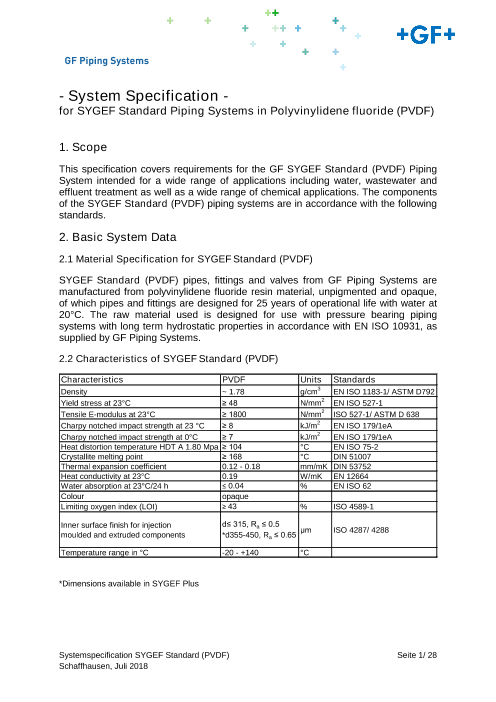
2.2 Characteristics of SYGEF Standard (PVDF)
Characteristics PVDF Units Standards
Density ~ 1.78 g/cm3 EN ISO 1183-1/ ASTM D792
Yield stress at 23°C ≥ 48 N/mm2 EN ISO 527-1
Tensile E-modulus at 23°C ≥ 1800 N/mm2 ISO 527-1/ ASTM D 638
Charpy notched impact strength at 23 °C ≥ 8 kJ/m2 EN ISO 179/1eA
Charpy notched impact strength at 0°C ≥ 7 kJ/m2 EN ISO 179/1eA
Heat distortion temperature HDT A 1.80 Mpa ≥ 104 °C EN ISO 75-2
Crystallite melting point ≥ 168 °C DIN 51007
Thermal expansion coefficient 0.12 - 0.18 mm/mK DIN 53752
Heat conductivity at 23°C 0.19 W/mK EN 12664
Water absorption at 23°C/24 h ≤ 0.04 % EN ISO 62
Colour opaque
Limiting oxygen index (LOI) ≥ 43 % ISO 4589-1
Inner surface finish for injection d≤ 315, Ra ≤ 0.5
moulded and extruded components *d355-450, Ra ≤ 0.65
μm ISO 4287/ 4288
Temperature range in °C -20 - +140 °C
*Dimensions available in SYGEF Plus
Systemspecification SYGEF Standard (PVDF) Seite 1/ 28
Schaffhausen, Juli 2018
GF Piping Systems
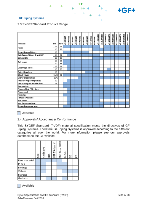
2.3 SYGEF Standard Product Range
Products PN SDR
Pipes 16 21
10 33
Socket fusion fittings 16
Butt fusion fittings IR and BCF 16 21
compatible 10 33
Ball valves 16 21
10 33
Diaphragm valves 16 21
10 33
Butterfly valves 10
Check valves 16/10 21
Wafer check valves 10/6
Pressure regulating valves 10
Ventilating and Bleed valves 16
Automation
Flanges PP-V / PP - Steel
Flange seal
Pipe clips
IR fusion machine
BCF fusion
Butt fusion machine
Socket fusion machine
Available
2.4 Approvals/ Acceptance/ Conformance
This SYGEF Standard (PVDF) material specification meets the directives of GF
Piping Systems. Therefore GF Piping Systems is approved according to the different
categories all over the world. For more information please see our approvals
database on the GF website.
Raw material
Pipes
Fittings
Valves
Flanges
Gaskets
Available
Systemspecification SYGEF Standard (PVDF) Seite 2/ 28
Schaffhausen, Juli 2018
DIBt
AMSE BPE
FDA
USP 25 class VI
FM-4910 listing
GOST-R d16 DN10
d20 DN15
CE
d25 DN20
BV d32 DN25
d40 DN32
d50 DN40
d63 DN50
d75 DN65
d90 DN80
d110 DN100
d125 DN100
d140 DN125
d160 DN150
d200 DN200
d225 DN200
d250 DN250
d280 DN250
d315 DN300
GF Piping Systems
3. Pipes
All SYGEF Standard (PVDF) pipes are metric sizes from d16 (3/8") – d315 (12"),
manufactured in accordance with the requirements of EN ISO 10931, as supplied by
GF Piping Systems. Furthermore the pipes are manufactured stress free and
thermally annealed (max. internal stress of 2.5 N/mm2), without any voids, allowing a
high grade of roundness, high degree of straightness and an extreme smooth surface
(see „2.2 Characteristics of SYGEF Standard (PVDF)” – Inner surface finish for
injection moulded and extruded components). Testing will be done in accordance
with EN 10204.
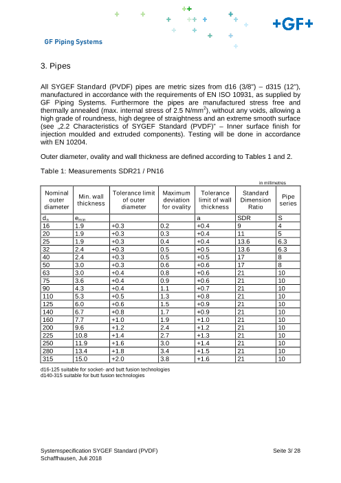
Outer diameter, ovality and wall thickness are defined according to Tables 1 and 2.
Table 1: Measurements SDR21 / PN16
in millimetres
Nominal Min. wall Tolerance limit Maximum Tolerance Standard outer thickness of outer deviation limit of wall Dimension
Pipe
diameter diameter for ovality thickness Ratio series
dn emin a SDR S
16 1.9 +0.3 0.2 +0.4 9 4
20 1.9 +0.3 0.3 +0.4 11 5
25 1.9 +0.3 0.4 +0.4 13.6 6.3
32 2.4 +0.3 0.5 +0.5 13.6 6.3
40 2.4 +0.3 0.5 +0.5 17 8
50 3.0 +0.3 0.6 +0.6 17 8
63 3.0 +0.4 0.8 +0.6 21 10
75 3.6 +0.4 0.9 +0.6 21 10
90 4.3 +0.4 1.1 +0.7 21 10
110 5.3 +0.5 1.3 +0.8 21 10
125 6.0 +0.6 1.5 +0.9 21 10
140 6.7 +0.8 1.7 +0.9 21 10
160 7.7 +1.0 1.9 +1.0 21 10
200 9.6 +1.2 2.4 +1.2 21 10
225 10.8 +1.4 2.7 +1.3 21 10
250 11.9 +1.6 3.0 +1.4 21 10
280 13.4 +1.8 3.4 +1.5 21 10
315 15.0 +2.0 3.8 +1.6 21 10
d16-125 suitable for socket- and butt fusion technologies
d140-315 suitable for butt fusion technologies
Systemspecification SYGEF Standard (PVDF) Seite 3/ 28
Schaffhausen, Juli 2018
GF Piping Systems
Table 2: Measurements SDR33 / PN10
in millimetres
Nominal Min. wall Tolerance limit Maximum Tolerance Standard outer thickness of outer deviation limit of wall Dimension
Pipe
diameter diameter for ovality thickness Ratio series
dn emin a SDR S
75 2.3 +0.4 0.9 +0.5 33 16
90 2.8 +0.4 1.1 +0.5 33 16
110 3.4 +0.5 1.3 +0.6 33 16
125 3.9 +0.6 1.5 +0.6 33 16
140 4.3 +0.8 1.7 +0.7 33 16
160 4.9 +1.0 2.0 +0.7 33 16
200 6.2 +1.2 2.4 +0.9 33 16
225 6.9 +1.4 2.7 +0.9 33 16
250 7.7 +1.6 3.0 +1.0 33 16
280 8.6 +1.8 3.4 +1.1 33 16
315 9.7 +2.0 3.8 +1.2 33 16
d75-125 suitable for socket- and butt fusion technologies
d140-315 suitable for butt fusion technologies
The mean outer diameter (dem) is the average value which results from the
measurements of the outer diameter at an interval of dn and 0.1 dn to the end of the
test piece. It is determined by measuring the circumference to 0.1 mm accuracy with
a measuring tape.
The mimimum and maximum wall thickness is determined to 0.1 mm, whereby the
measurement points should be distributed on the pipe circumference as evenly as
possible. All measured values must be within the allowable tolerance limit.
Ovality is the difference between the measured maximum and the measured
minimum external diameter (de) at the same cross-section. It is calculated to 0.1 mm
and measured immediately after production. The ovality requirement applies to the
timepoint of manufacture.
3.1 Product Marking
The pipes are embossed with a permanent identification during the production
process to ensure full traceability.
All pipes are marked permanently and consecutively
• Material identification: +GF+ SYGEF Std or SYGEF Plus Std
• Material code: PVDF
• Pipe diameter, wall thickness, SDR and PN
• Product standard: ISO 10931
• Manufacture date, shift and machine number
• Approvals / Conformance: DIBT-Approval, FM4910 listing
Systemspecification SYGEF Standard (PVDF) Seite 4/ 28
Schaffhausen, Juli 2018
GF Piping Systems
3.2 Packaging and Labelling
The packaging must ensure that the pipes are not damaged during transportation.
Packaging and labelling must meet the following requirements:
• Pipes capped on each end
• Each pipe separately and single bagged in a specified bagging material
• Identification of the content, in type, quantity and product details
• Information about standards and approvals covered by the product
• Content of the label must fulfil legal requirements
• Labels must be EAN coded for automatic identification
• Comply to GF standards as well as to international standards such as ISPM
15
4. Fittings
All SYGEF Standard (PVDF) fittings are either as butt fusion type, metric sizes d20
(1/2") – d315 (12”) or socket fusion type, metric size d16 (3/8”) – d63 (2”). Both are
manufactured by GF Piping Systems in accordance with EN ISO 10931 and they
need to be tested according to EN 10204. The fittings are manufactured with an
extreme smooth surface (Ra-value ≤ 0,5 μm for all injection moulded items). All
threaded connections have pipe threads in accordance with the requirements of ISO
7-1.
All butt fusion fittings are manufactured with optimal lengths designed for use with
fusion machine IR-63 Plus, IR-110 Plus, IR-110 A, IR-225 Plus, IR-315 Plus, IR-315
A, IR-450 or the BCF Plus (Bead and Crevice Free) welding machine supplied by GF
Piping Systems.
4.1 Product Marking
The fittings are embossed with a permanent identification during the production
process to ensure full traceability.
Each part is marked according to EN ISO 10931:
• Logo of the manufacturer
• SDR (Standard Dimension Ratio) rating or PN (Nominal Pressure) or s (pipe
series)
• Dimension
• Material
• Permanently embossed date indicating the year and the production series
4.2 Packaging and Labelling
The packaging must ensure that the fittings are not damaged during transportation.
Packaging and labelling must meet the following requirements:
• Multiple components separately and single bagged in specified bagging
material
• Identification of the content, in type, quantity and product details
• Information about standards and approvals covered by the product
• Content of the label must fulfil legal requirements
• Labels must be EAN coded for automatic identification
• Comply to GF standards as well as to international standards such as ISPM 15
Systemspecification SYGEF Standard (PVDF) Seite 5/ 28
Schaffhausen, Juli 2018
GF Piping Systems
5. Accessories
5.1 Backing Flanges
Backing flanges in metric sizes DN15-400 shall be designed according to ISO 9624,
in a thermo plastic-oriented design, consisting of 100% glass fibre reinforced
polypropylene, PP-GF30, graphite black and UV stabilized. These flanges are
manufactured in a seamless technology injection moulding process by GF Piping
Systems. The flange is optimized with a V-groove in the inner diameter to ensure an
evenly distributed force on the thermo plastic flange adapter. The backing flanges
shall be marked with dimension, PN-value, standards, brand and lot number.
Connecting dimensions metric according to ISO 7005, EN 1092; Bolt circle diameter
PN10; Inch: ANSI B 16.5, BS 1560; class 150 (1/2” – 12”).
As an alternative backing flanges in metric sizes DN15-400 shall be designed
according to ISO 9624, in a thermo plastic-oriented design, consisting of glass fibre
reinforced polypropylene, PP-GF30, graphite black and UV stabilized with steel
inserts. The backing flanges shall be marked with dimension, PN-value, standards,
brand and lot number. Connecting dimensions metric according to ISO 7005,
EN 1092; Bolt circle diameter PN10 (DN15-400) + PN16 (DN15-400); Inch: ANSI B
16.5, BS 1560; class 150 (1/2” – 8”).
As an alternative backing flanges ANSI sizes d355 DN350 14” – d450 DN450 18”
shall be designed in a thermo plastic-oriented design, consisting of PVDF coated
steel. Connecting dimensions Inch ANSI B16.5, BS1560, class 150 (14”-16”).
5.2 Gaskets
Gaskets in metric sizes DN10–450 shall consist of elastomeric material according to
EN681, designed with or without metal reinforcement for use with flange adaptors
according ISO 10931. Gaskets with reinforcement shall be designed to be centred by
the outer diameter. Gaskets without reinforcement >DN100 shall provide fixation aids
to fit on the flange bolts.
5.3 Pipe Support System
Pipe Support System shall be KLIP-IT sizes d16-315 supplied by GF Piping Systems.
Systemspecification SYGEF Standard (PVDF) Seite 6/ 28
Schaffhausen, Juli 2018
Page7
All SYGEF Standard (PVDF) ball valves with metric sizes DN10–100 shall be GF Piping Systems Type 546, 543, 523 with true double union design manufactured by GF Piping Systems in accordance with EN ISO 16135. Incorporated into its design shall be a saf...、6.1.1 Electrically Actuated Ball Valves
GF Piping Systems
6. Valves
All SYGEF Standard (PVDF) valves shall be metric sizes manufactured by GF
Piping Systems or equal in accordance with EN ISO 16135, 16136, 16137, 16138,
tested according to the same standard.
6.1 Ball Valves
All SYGEF Standard (PVDF) ball valves with metric sizes DN10–100 shall be GF
Piping Systems Type 546, 543, 523 with true double union design manufactured by
GF Piping Systems in accordance with EN ISO 16135. Incorporated into its design
shall be a safety stem with a predetermined breaking point above the bottom O-ring,
preventing any media leaking in the event of damage. The valve nut threads shall be
buttress type to allow fast and safe radial mounting and dismounting of the valve
during installation or maintenance work. Seats shall be PTFE with backing rings
creating self-adjusting seals and constant operating torque. Backing rings and seals
shall be EPDM or FKM. The handle shall include in its design an integrated tool for
removal of the union bush. Union bushes shall have left-hand threads to prevent
possible unscrewing when threaded end connectors are removed from pipe.
The following accessories shall be available:
• A Multi-Functional Model (MFM) in PPGF equipped with internal limit switches
for reliable electrical position feedback, is mounted directly between the valve
body and the valve handle. This MFM is also the necessary interface for later
mounting of actuators.
• Mounting plate in PPGF with integrated inserts for later screw mounting on
any support
• Lockable multi-functional handle
6.1.1 Electrically Actuated Ball Valves
Electric actuators shall be Typees EA15 (metric sizes DN10-50), EA25 (metric sizes
DN10-50), EA45 (metric sizes DN65) and EA120 (metric sizes DN80-100) shall be
available manufactured by GF Piping Systems in accordance with EN 61010-1, EC
directives 89/336/EWG-EMV and 73/23/EWG (LVD). Additionally they need to be CE
marked. Actuator housing shall be made of PPGF (polypropylene glass fibre
reinforced), flame retardant with external stainless steel screws. All electric actuators
shall have an integrated emergency manual override and integrated optical position
indication.
All electric actuator typees (with the exception of EA15) shall have the following
accessories available:
Systemspecification SYGEF Standard (PVDF) Seite 7/ 28
Schaffhausen, Juli 2018
GF Piping Systems
Accessories
EA15 / EA25 / EA45 / EA120 / EA250:
• Failsafe return unit
Battery incorporated into the housing for moving to a safe position in case of
power outage (open or closed).
EA25 / EA45 / EA120 / EA250:
• positioner
For continuous valve control with 4-20mA or 0-10V and 4-20mA feedback
• Monitoring board
• Cycle time extension
• Cycle time monitoring
• Cycle counter
• Motor current monitoring
• Fieldbus connection
• Profibus DP auxiliary card
• AS interface module
The system Specifications for electric actuators are as follows:
* at rated torque
Specification
Combinations EA15 2-Way Ball valve type 546 bis DN50
3-Way Ball valve type 543 bis DN50
EA25 2-Way Ball valve type 546 bis DN50
3-Way Ball valve type 543 bis DN50
EA45 2-Way Ball valve type 546 bis DN65
Butterfly valve types 567/578, Type 038/039
EA120 2-Way Ball valve type 546 bis DN100
Butterfly valve types 567/578, Type 038/039
EA250 Butterfly valve types 567/578, Type 038/039
Rated voltage AC 100 – 230 V, 50/60 Hz
AC/DC 24 V, 50/60 Hz
Rated voltage tolerance - 10 … + 15 %
Protection class IP67per EN 60529
Contamination level 2 according to EN 61010-1
Overload protection Current/time-dependent (resetting)
Overvoltage category II
Ambient temperature -10 °C to +45 °C
Allowable humidity Max. 90% relative humidity, non-condensing
Housing material PP-GF for very good chemical resistance
Systemspecification SYGEF Standard (PVDF) Seite 8/ 28
Schaffhausen, Juli 2018
GF Piping Systems
EA15 EA25 EA45 EA120 EA250
Power input max. 45 VA 45 VA 65 VA 60 VA 70 VA
Rated torque MDN. 10 (20) 10 (25) 20 (45) 60 (120) 100 (250)
(peak)
Duty cycle at 25 °C / 15 40% 100% 50 % 50 % 35 %
min
Cycle time s/90 at Mdn. 5s 5 s 6s 15 s 20 s
Connection F05 F05 F05 F07 F07
Tested cycles (at 20 °C 150 000 250 000 100 000 100 000 75 000
and Mdn.)
Weight 1.85 kg 2.193 kg 2.193 kg 3.356 kg 4.995 kg
Actuating angle Max. 355°, set to 90 °
6.1.2. Pneumatically Actuated Ball Valves
Pneumatic actuators shall be GF Piping Systems Types PA11 (for valve sizes DN15-
25) and PA21 (for valve sizesDN32-50). They shall be manufactured by GF Piping
Systems. Pneumatic actuators shall be available as fail safe close, fail safe open and
double acting and have an integrated optical position indication. Actuator housing
shall be made of Polypropylene fibre glass reinforced (PPGF) and flame retardant.
Actuators shall contain a preloaded spring assembly to ensure safe actuator
operation and maintenance. Actuators shall contain integrated Namur interface (ISO
5211) for the easy mounting of positioners, limit switches and accessories. The valve
shall be equipped with a Multi-functional-module for reliable electric feedback,
mounted directly between the valve body and the actuator as manufactured by GF
Piping Systems.
• For valve size DN65 pneumatic actuators shall be Type PA30 (fail safe to
close or open function), Type PA35 (double acting function).
• For valve size DN80 pneumatic actuators shall be Type PA35 (fail safe to
close or open function), Type PA40 (double acting function).
• For valve size DN100 pneumatic actuators shall be Type PA45 (fail safe to
close or open function), Type PA45 (double acting function)
Pneumatic actuators shall have an integrated optical position indicator. Actuator
housing shall be made of hardened anodized aluminium. Actuators shall contain
integrated Namur interface for the easy mounting of positioners, limit switches and
accessories.
All pneumatically actuated ball valves shall have the following accessories available:
Systemspecification SYGEF Standard (PVDF) Seite 9/ 28
Schaffhausen, Juli 2018
GF Piping Systems
• Pilot valve remote or direct mounted in voltages 24VDC/AC, 110VAC,
230VAC
• Positioner Type DSR 500-3
• Limit switch kits AgNi, Au, NPN, PNP
• Stroke limiter
• Manual override for all sizes up to DN100
• AS Interface control module with incorporated position feedback and a
solenoid pilot valve
6.2 Diaphragm Valves
6.2.1 Manual Diaphragm Valves
6.2.1.1 Diaphragm Valves DN15 to DN100
All SYGEF Standard (PVDF) diaphragm valves, with metric sizes DN15-100, shall
be either:
• Type 514 (true double union design, DN15-50), or
• Type 515 (spigot design, DN15-50), or
• Type 517 (flange design, DN15-50), or
• Type 519 (T-type design, DN15-15 – DN100-50)
All diaphragm valves shall be manufactured by GF Piping Systems in accordance
with EN ISO 16138.
The upper body shall be orange PPGF (polypropylene glass fibre reinforced)
connected to the lower body with a central union avoiding exposed screws.
A two coloured position indicator integrated into the hand wheel must be present to
determine diaphragm position. The hand wheel shall have an integrated locking
mechanism.
Diaphragms are EPDM, FKM, NBR, PTFE with EPDM or FKM backing diaphragm.
Following options shall be available:
• PN16 pressure rating (upper body shall be black PPS GF (polyphenylene
sulphide glass fiber reinforced) for water applications only)
• Electrical feedback unit with either AgNi or AU contacts
• Pressure proof housing
The diaphragm valve shall have following KV values:
d DN KV
[mm] [mm] [l/min @ ΔP=1 bar]
20 15 125
25 20 271
32 25 481
40 32 759
50 40 1263
63 50 1728
Systemspecification SYGEF Standard (PVDF) Seite 10/ 28
Schaffhausen, Juli 2018
GF Piping Systems
6.2.1.2 Diaphragm Valves DN65 to DN150
All SYGEF Standard (PVDF) diaphragm valves, with metric sizes, shall be Type 317
(flanged design, DN65-150)
All diaphragm valves shall be manufactured by GF Piping Systems in
accordance with EN ISO 16138. The upper body shall be PPGF (polypropylene glass
fibre reinforced) connected to the lower body with exposed stainless steel bolts. A
position indicator integrated into the hand wheel must be present to determine
diaphragm position. Diaphragms are to be EPDM, FKM, NBR, or PTFE with EPDM or
FKM backing diaphragm.
6.2.2 Pneumatic Diaphragm Valves
6.2.2.1 Pneumatic Diaphragm Valves DN15 to DN100
All SYGEF Standard (PVDF) diaphragm valves, with metric sizes DN15-100, shall
be either:
• Type 604 true double union design, DN15, or
• Type 605 spigot design, DN15
• Type 6x4 true double union design, DN15-50, or
• Type 6x5 spigot design, DN15-50, or
• Type 6x7 flange design, DN15-50, or
• Type 6x9 T-type design, DN15-15 – DN100-50
All diaphragm valves shall be manufactured by GF Piping Systems in accordance
with EN ISO 16138. The upper body shall be connected to the lower body with a
central union avoiding exposed screws.
Diaphragms are EPDM, FKM, NBR, PTFE with EPDM or FKM backing diaphragm.
Following options shall be available:
The diaphragm valve shall have following KV values:
d DN KV
[mm] [mm] [l/min @ ΔP=1 bar]
20 15 125
25 20 271
32 25 481
40 32 759
50 40 1263
63 50 1728
Pneumatic actuators shall be GF Piping Systems Type DIASTAR or Type 604/605
and available as:
• Type 604/605 for PN up to 6 bar (one side)
• DIASTAR Ten for PN up to 10 bar (one side)
• DIASTAR Ten Plus for PN up to 10 bar (both sides)
• DIASTAR Sixteen for PN up to 16 bar (one side)
Systemspecification SYGEF Standard (PVDF) Seite 11/ 28
Schaffhausen, Juli 2018
Page12
6.3 Butterfly Valves
GF Piping Systems
The mode of operation shall be fail safe close (FC), fail safe open (FO) and double
acting (DA). The valves shall have an integrated optical position indicator. Actuator
housing shall be made of PPGF (polypropylene glass fibre reinforced). Actuators with
FC mode shall contain a preloaded galvanised steel spring assembly to ensure safe
actuator operation and maintenance. The actuator DIASTAR Ten, DIASTAR Ten
Plus and DIASTAR Sixteen shall have following accessories available:
• Solenoid pilot valve remote or direct mounted in voltages 24VDC/AC,
110VAC, 230VAC
• Positioner Type DSR 500-1
• Feedback with following limit switches AgNi, Au, NPN, PNP, NAMUR
• Stroke limiter & emergency manual override
• ASI controller
6.2.2.2 Pneumatic Diaphragm Valves DN65 to DN150
All SYGEF Standard (PVDF) diaphragm valves with metric sizes shall be flanged
design, DN65-150.
All diaphragm valves shall be manufactured by GF Piping Systems in
accordance with EN ISO 16138. The upper body shall be connected to the lower
body with exposed stainless steel bolts. Diaphragms are to be EPDM, FKM, NBR, or
PTFE with EPDM or FKM backing diaphragm.
Pneumatic diaphragm actuators shall be GF Piping Systems DIASTAR Type 025.
The mode of operation shall be fail safe close (FC), fail safe open (FO) and double
acting (DA). The valves shall have an integrated optical position indicator. Actuator
housing shall be made of PPGF (polypropylene glass fibre reinforced). Actuators with
FC mode shall contain a preloaded galvanised steel spring assembly to ensure safe
actuator operation and maintenance.
The actuator DIASTAR 025 shall have following accessories available:
• Solenoid pilot valve remote or direct mounted in voltages 24VDC/AC,
110VAC, 230VAC
• Positioner Type DSR 500-2
• Feedback with following limit switches AgNi, Au, NPN, PNP, NAMUR
• Stroke limiter & emergency manual override
• ASI Controller
6.3 Butterfly Valves
All SYGEF Standard (PVDF) butterfly valves with metric sizes DN50 (2") – DN300
(12") shall be GF Piping Systems Type 567/578/563 wafer/lug type with a double
eccentric disc design manufactured by GF Piping Systems in accordance with EN
ISO 16136. Seals shall be available in both FKM and PTFE. The lever handle shall
be lockable in increments of 5 degrees. There shall always be six teeth engaged
between the ratchet and the index plate to ensure accurate and safe positioning of
the lever. There shall be the option of fine adjustment by use of a specific hand lever,
allowing the disc to be exposed at any angle between 0° und 90°. The hand lever
shall be manufactured of high strength PPGF (polypropylene glass fibre reinforced).
Systemspecification SYGEF Standard (PVDF) Seite 12/ 28
Schaffhausen, Juli 2018
GF Piping Systems
The option of an integrated electric position indicator shall be available. Optional the
valves can be actuated by gear box with hand wheel. The electric position indicator
shall be integrated into the mounting flange. Butterfly valves shall have low actuation
torque to enable easy operation. All butterfly valves Type 567/578 manufactured by
GF Piping Systems are designed for a nominal pressure rate of 10 bar. All butterfly
valves Type 563 are designed for a nominal pressure rate of 4 bar.
6.3.1 Electrically Actuated Butterfly Valves
Electric actuators shall be GF Piping Systems Types EA45, EA120 or EA250
dependent on valve size. For valve size from DN350 - 600 with Valpes VS300,
VT600 and VT1000. They shall be manufactured by GF Piping Systems in
accordance with EN 61010-1, as per the above specifications. Actuator housing shall
be made of PPGF (polypropylene glass fibre reinforced), flame retardant and feature
external stainless steel screws. All electric actuators shall have an integrated
emergency manual override and integrated optical position indication. All electric
actuator types shall have the following accessories available:
• Failsafe return unit
Battery incorporated into the housing for moving to a safe position in case of
power outage (open or closed).
• positioner
For continuous valve control with 4-20mA or 0-10V and 4-20mA feedback
• Monitoring board
• Cycle time extension
• Cycle time monitoring
• Cycle counter
• Motor current monitoring
• Fieldbus connection
• Profibus DP auxiliary card
• AS interface module
6.3.2 Pneumatically Actuated Butterfly Valves
Pneumatic actuators shall be GF Piping Systems Types PA 35 (metric sizes DN50-
65), PA40 (metric size DN80), PA45 (metric size DN100-125), PA55 (metric size
DN150-200), PA60 (metric sizes DN200 FC), PA65 (metric sizes DN250 FC) PA70
(metric sizes DN300 FC). For valve size from DN350 – 600 with Revac types.They
shall be supplied by GF Piping Systems. Pneumatic actuators shall be available as
fail safe close, fail safe open and double acting and have an integrated optical
position indication. Actuator housing shall be made of hardened anodized aluminium.
Actuators shall contain integrated Namur interfaces (ISO 5211) for the easy mounting
of positioners, limit switches and accessories. All pneumatically actuated butterfly
valves shall have the following accessories available:
• Solenoid pilot valve remote or direct mounted in voltages 24VDC/AC,
110VAC, 230VAC
Systemspecification SYGEF Standard (PVDF) Seite 13/ 28
Schaffhausen, Juli 2018
Page14
The wafer check valves are dimensioned in metric sizes DN32-125 for nominal pressure 10 bar and in metric sizes DN150-300 for nominal pressure 6 bar.、6.5 Pressure Regulating Valves
GF Piping Systems
• Positioner Type DSR 100/101
• Feedback with following limit switches AgNi, Au, NPN, PNP, NAMUR
• Stroke limiter & emergency manual override
• ASI-controller
6.4 Check Valves
6.4.1 Check Valves
All SYGEF Standard (PVDF) check valves, according to EN ISO 16137, metric sizes
DN10-100 metric, shall be Type 561/562 true double union design. Seals shall be
FKM or FFKM. Union bushes shall have a left hand thread to prevent possible
unscrewing when threaded end connectors are removed from pipe. This valve shall
be suitable for mounting in a vertical and horizontal position. Type 562 shall be
equipped with a spring made of stainless steel (either V2A, Nimonic 90 or V2A
ECTFE coated) to allow position independent installation. The valves are designed
for a nominal pressure of 16 bar.
6.4.2 Wafer Check Valves
All SYGEF Standard (PVDF) wafer check valves shall be GF Piping Systems Type
369, metric size DN32-300. The minimum water column of 2m is required for sealing.
They must be equipped with a spring (either in 316 stainless steel or Hasteloy C)
guaranteeing closure in all installation positions. Attention: A stabilizing pipe zone of
at least 5 times nominal diameter (DN) (recommended 10 times nominal diameter)
before and after the wafer check valve should be provided.
The wafer check valves are dimensioned in metric sizes DN32-125 for nominal
pressure 10 bar and in metric sizes DN150-300 for nominal pressure 6 bar.
6.5 Pressure Regulating Valves
All pressure regulating valves as supplied by GF Piping Systems shall have the
following characteristics:
Pressure ranges for all pressure regulating valves are the following:
• DN10–50 from 0 up to max. 10 bar
• DN65–80 from 0 up to max. 6 bar
• DN100 from 0 up to max. 4 bar
6.5.1 Pressure Reducing Valves
As supplied by GF Piping Systems reduces the pressure within the system to a pre-
set value. By using the differential pressure, the pressure reducing valve adjusts itself
to the set working pressure.
The outlet pressure (working pressure) is not directly related to the inlet pressure. If
the outlet pressure increases above the set value, the diaphragm is lifted against the
spring force. If the outlet pressure falls below the set value, the diaphragm is pressed
down by the spring force. The pressure reducing valve begins to close/open until a
state of equilibrium is re-established; in other words, the outlet pressure remains
constant irrespective of an increasing or decreasing inlet pressure. Following types
and sizes are available:
Systemspecification SYGEF Standard (PVDF) Seite 14/ 28
Schaffhausen, Juli 2018
GF Piping Systems
Systemspecification SYGEF Standard (PVDF) Seite 15/ 28
Schaffhausen, Juli 2018
GF Piping Systems
• Type 582, compact Pressure Reducing Valve, sizes DN10–50
Features:
• Metal free central housing union nut
• Set pressure selectable 0 - 9 bar or 0.3 – 3 bar
• Manometer optional
• Manometer assembly possible on both sides
• Selection of direct manometer assembly or with gauge guard
• Possibility to show either inlet or outlet pressure
• Injection molded directional arrow for direction of flow
• Threaded inserts for assembly
Type V82, Pressure Reducing Valve with an integrated manometer, sizes DN65-100
6.5.2 Pressure Retaining Valves
As supplied by GF Piping Systems serves to keep the working or system related
pressures constant, to balance out pressure pulsation, and to reduce pressure peaks
in chemical process systems. If the inlet pressure rises above the set value, the
pressurized valve piston is lifted against the spring force. Consequently, the valve
opens and there is a reduction of pressure through the outlet pipe. The valve closes
as soon as the inlet pressure sinks below the pre-set spring tension.
Following types and sizes are available:
• Type 586, compact Pressure Retaining Valve, sizes DN10-50
Features:
• Metal free central housing union nut
• Set pressure selectable 0 - 9 bar or 0.3 – 3 bar
• Manometer optional
• Manometer assembly possible on both sides
• Selection of direct manometer assembly or with gauge guard
• Possibility to show either inlet or outlet pressure
• Injection molded directional arrow for direction of flow
• Threaded inserts for assembly
• Type V86, Pressure Retaining Valve, sizes DN65-100
Systemspecification SYGEF Standard (PVDF) Seite 16/ 28
Schaffhausen, Juli 2018
GF Piping Systems
6.6 Direct-acting Solenoid Valves
Direct-acting solenoid valves as supplied by GF Piping Systems serve to regulate
and control fluids, if no compressed air is available or not wanted. They are used for
diverse functions, e.g. opening, shutting, dosing, distribute and mixing. The medium
flow is switched directly by the armature moved by the magnetic force.
• Safety position shall be available
Following type and sizes are available:
• Type 157, sizes DN4-8
• Type 160/161, sizes DN10-20
• Type 166, sizes DN3-5
6.7 Servo-assisted Solenoid Valves
Servo-assisted solenoid valves as supplied by GF Piping Systems serve to regulate
and control fluids, if no compressed air is available or unwanted. They are used for
miscellaneous functions, e.g. opening, shutting, dosing, distributing and mixing.
Opening large orifices using the direct-acting method would require enormous and
expensive coils. Servo assisted valves use the power of the fluid to open the flow
channel by controlling a small pilot channel to alter the forces on a larger main seal.
∆p (pressure) 0.5 bar is mandatory with servo-assisted valves.
• Type, 165, sizes DN10-50
6.8 Ventilating- and Bleed Valves
All SYGEF Standard (PVDF) ventilating- and bleed valves shall be GF type 591.
Dimensions DN10-100 are with pressure rating PN16. They shall be equipped with a
PVDF floater.
6.9 Ventilating Valves
All SYGEF Standard (PVDF) ventilating valves shall be GF type 595. Dimensions
DN10-100 are with pressure rating PN16. They shall be equipped with plastic coated
stainless steel spring with minimal opening pressure (10-80 mbar). Optionally
Nimonic / Nimonic-ECTFE can be used.
Systemspecification SYGEF Standard (PVDF) Seite 17/ 28
Schaffhausen, Juli 2018
GF Piping Systems
7. Welding and assembly
All butt fusion fittings and valves shall also be manufactured with laying lengths
designed for use with fusion machines IR-63 Plus, IR-110 Plus, IR-225 Plus and IR-
315 Plus from GF Piping Systems, providing welds with increased mechanical and
chemical stability than conventional welding methods (socket- and butt fusion).
The IR Plus fusion machines use non-contact radiant heating. The cooling time for is
calculated on the basis of ambient temperature and the bead surface temperature for
uniform reproducible weld beads for easy weld bead inspection. To increase the
cooling capacity, an additional cooling fan is included in the IR-225 Plus and IR-315
Plus.
Only authorised welders by GF Piping Systems are allowed to perform fusion on the
IR Plus machines.
As an alternative to IR fusion, conventional butt fusion according to DVS 2207-15
may be used, preferably with automated CNC controllers and weld recorders. Special
care needs to be taken to prevent the pipe ends from sticking to the heater plate.
Socket fittings require the use of Socket Fusion welding tools according to DVS
2007-15, with heating bushes System B.
The BCF fusion technology joins SYGEF Standard (PVDF) piping components of
dimensions d20-110 without any irregularities, beads or crevices. The extremely
compact fusion machine, which is also ideal for on-site fusion, is very reliable, easy
to handle and creates reproducible and very strong fusion welds.
Only authorized welders by GF Piping Systems are allowed to perform fusion on the
BCF Plus machines manufactured by GF Piping Systems.
The welding and the installation should be in accordance with GF Piping Systems
Guide to the Installation and Use of Plastic Pipeline.
Systemspecification SYGEF Standard (PVDF) Seite 18/ 28
Schaffhausen, Juli 2018
Page19
8. Measurement & Control / Instrumentation
GF Piping Systems
8. Measurement & Control / Instrumentation
The following parameters can be measured (Sensors), indicated and/ or transmitted
(transmitters) to PLC, PC and other Data Acquisition Systems. All products comply
with the CE standard.
Parameter Technology Compatible liquids (*)
Flow Paddlewheel clean liquids
Rotameter clean liquids
Magmeter contaminated liquids
Level Hydrostatic/Ultrasonic/Radar all liquids
pH-ORP Glas electrodes all liquids
Conductivity Contact all liquids
Pressure Piezoresistive all liquids
Temperature Pt1000 all liquids
(*) please check first the sensors limitations in material, pressure and temperature (data sheet) and chemical
resistance list
8.1 Sensors
The sensors listed hereafter will transfer the measured value to a GF Piping Systems
Transmitter, to indicate the measured value and allowing simple calibration and
maintenance of the devices. Alternatively the measured values of the sensors can be
sent directly to a PLC, PC or other local made electronics using either an analogue
signal (4-20mA, open collector or sinusoidal voltage) or a digital signal called S3L
(GF Piping Systems Signet serial signal).
8.1.1 Installation Fittings
Installation fittings consist of a body out of PP-H or PVC-U with connection elements
PE. Depending on the sensor type, special installation fittings shall be used for
connection to the pipeline: Installation T-Fitting sizes d20-63 with double true union in
PP, Wafer fitting made out of PP-H in sizes d75–315mm and weld-o-let made out of
PE100 in sizes d75–630mm supplied by GF Piping Systems. Sensor thread
connection shall be 1¼" NPSM.
Systemspecification SYGEF Standard (PVDF) Seite 19/ 28
Schaffhausen, Juli 2018
GF Piping Systems
8.1.2 Flow sensors
8.1.2.1 Paddlewheel sensors
515 and 525 sensors:
All sensors of this family are “sinusoidal” sensors. This sensor from GF Piping
Systems SIGNET requires no external power source to produce a signal. Internal to
the body of the sensor is a wire coil which when excited by the rotor assembly
produces a small sinusoidal signal. The rotor assembly consists of four paddles;
inserted into each of the paddles of the rotor are magnets. As liquid flows past the
rotor assembly it rotates each of the four paddles produces a sine wave signal as it
passes the centre of the body (two paddles of the rotor produces a full AC sine
wave).
The sensors as manufactured by GF Piping Systems SIGNET produce a signal
output which is proportional to the flow rate. A K-factor (number of pulses generated
by the sensor per 1 liter or 1 gallon of fluid the sensor) is used to define the size of
the pipe that the sensor is inserted into.
3-2536 and 3-2537 sensors:
All sensors of this family of sensors are “Hall Effect” sensors. Internal to the GF
Piping Systems SIGNET sensors body is an open collector relay. The sensor is
supplied with a voltage from the 3-8550 transmitters or an external power supply
ranging from 5 to 24 volts. This voltage is switched through the open collector relay
as the paddlewheel (rotor) of the sensor rotates. The sensor’s rotor assembly has
four paddles. Inserted in two of the paddles is a magnet. As the paddles pass the
centre of the sensors body, the magnetic field switches the open collector relay on
and off which generates a square wave pulse as manufactured by GF Piping
Systems SIGNET. Two pulses indicates a complete rotation (on/off cycle) of the open
collector relay. The pulse output is directly proportional to the fluid velocity. A K-factor
(number of pulses generated by the sensor per 1 liter or 1 gallon of fluid passing the
sensor) is used to define the size of the pipe that the sensor is inserted into.
8.1.2.2 Rotameters
As supplied by GF Piping Systems are radially installed dismountable meters for flow
rate measuring in industrial piping applications. If needed, minimum or maximum flow
can also be monitored via limit switches. Also, analogue flow measurement with a
4…20mA Signal is possible.
Systemspecification SYGEF Standard (PVDF) Seite 20/ 28
Schaffhausen, Juli 2018