


Practice Guide for the Electrofusion Jointing of Larger Diameter Polyethylene Pressure Pipes
製品カタログ
TEPPFA Technical Guidance Document
Contents
1.Introduction
2.Safe and reliable site pre-conditions
3.Quality requirements
4.Installation procedure for Electrofusion socket fittings
5.Saddles
6.Typical failures and root causes
7.Checklist for planning
このカタログについて
| ドキュメント名 | Practice Guide for the Electrofusion Jointing of Larger Diameter Polyethylene Pressure Pipes |
|---|---|
| ドキュメント種別 | 製品カタログ |
| ファイルサイズ | 2.5Mb |
| 取り扱い企業 | ジョージフィッシャー株式会社 (この企業の取り扱いカタログ一覧) |
この企業の関連カタログ


このカタログの内容
Page1
TEPPFA Technical Guidance Document - AGU/2014/01
A Good Practice Guide for the Electrofusion
Jointing of Larger Diameter Polyethylene Pressure
Pipes
Contents
1. Introduction 5. Saddles
2. Safe and reliable site pre-conditions 6. Typical failures and root causes
3. Quality requirements 7. Checklist for planning
4. Installation procedure for Electrofusion socket fittings
1. Introduction
Polyethylene piping systems are being increasingly accepted in larger diameters (above 315 mm) as a result of
their proven performance advantages and the cost e ective installation techniques which can be employed.
Electrofusion (EF) is an important and reliable jointing method for polyethylene pipes and a wide range of EF
fittings approved to EN 12201-3/ EN 1555-3 are o ered in the market.
Usually EF training and certification is only applied to smaller dimensions, the common influencing factors for
good installation practices and the preventive measures to avoid welding failures are often not understood.
This document aims to provide general guidance only, and should be used in conjunction with more detailed
information from the specific pipe, fitting and equipment supplier.
1.1. Objectives of this document
The following guide provides universally valid recommendations for the safe and reliable jointing of large
diameter PE pipes using electrofusion techniques with the intention of preventing installation failures. The code
describes good installation practices independent of fitting design.
1.2. Scope
The Electrofusion jointing of PE pipes and pipe components above dn315mm for buried Gas & Water Utilities
and Sewage and Industrial Water applications.
1.3. Originators
This document was created by the Teppfa Utilities Application Group
1.4. Disclaimer
In the preparation of this document every e ort has been made to o er the most current, and accurate
information. However, to the broadest extent permitted by law, all information published or referenced in this
document is provided without any representation or warranty of any kind either expressed or implied. Changes
and additions to any information contained herein may be made by Teppfa without prior notification.
The Voice of the European Plastic Pipes and Fittings Industry
Page2
Page 2 TEPPFA Technical Guidance Document - AGC/2014/01
2. Safe and reliable site
pre-conditions
The following precautionary measures should be
employed to ensure a healthy and safe working
environment for operatives in the trench and to
generate conditions for secure and reliable jointing,
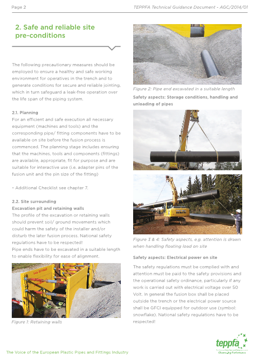
Figure 2: Pipe end excavated in a suitable length
which in turn safeguard a leak-free operation over
the life span of the piping system. Safety aspects: Storage conditions, handling and
unloading of pipes
2.1. Planning
For an e cient and safe execution all necessary
equipment (machines and tools) and the
corresponding pipe/ fitting components have to be
available on site before the fusion process is
commenced. The planning stage includes ensuring
that the machines, tools and components (fittings)
are available, appropriate, fit for purpose and are
suitable for interactive use (i.e. adapter pins of the
fusion unit and the pin size of the fitting)
• Additional Checklist see chapter 7.
2.2. Site surrounding
Excavation pit and retaining walls
The profile of the excavation or retaining walls
should prevent soil/ ground movements which
could harm the safety of the installer and/or
disturb the later fusion process. National safety
Figure 3 & 4: Safety aspects, e.g. attention is drawn
regulations have to be respected!
when handling floating load on site
Pipe ends have to be excavated in a suitable length
to enable flexibility for ease of alignment. Safety aspects: Electrical power on site
The safety regulations must be complied with and
attention must be paid to the safety provisions and
the operational safety ordinance, particularly if any
work is carried out with electrical voltage over 50
Volt. In general the fusion box shall be placed
outside the trench or the electrical power source
shall be GFCI equipped for outdoor use (symbol:
snowflake). National safety regulations have to be
Figure 1: Retaining walls respected!
The Voice of the European Plastic Pipes and Fittings Industry
Page3
Page 3 TEPPFA Technical Guidance Document - AGC/2014/01
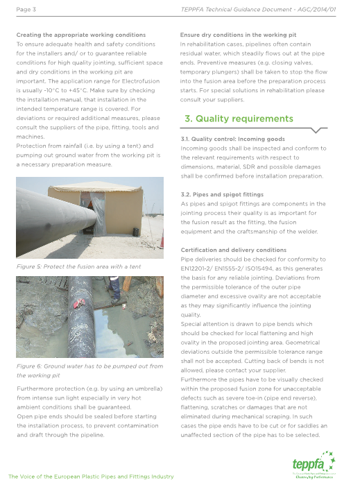
Creating the appropriate working conditions Ensure dry conditions in the working pit
To ensure adequate health and safety conditions In rehabilitation cases, pipelines often contain
for the installers and/ or to guarantee reliable residual water, which steadily flows out at the pipe
conditions for high quality jointing, su cient space ends. Preventive measures (e.g. closing valves,
and dry conditions in the working pit are temporary plungers) shall be taken to stop the flow
important. The application range for Electrofusion into the fusion area before the preparation process
is usually -10°C to +45°C. Make sure by checking starts. For special solutions in rehabilitation please
the installation manual, that installation in the consult your suppliers.
intended temperature range is covered. For
deviations or required additional measures, please 3. Quality requirements
consult the suppliers of the pipe, fitting, tools and
machines. 3.1. Quality control: Incoming goods
Protection from rainfall (i.e. by using a tent) and Incoming goods shall be inspected and conform to
pumping out ground water from the working pit is the relevant requirements with respect to
a necessary preparation measure. dimensions, material, SDR and possible damages
shall be confirmed before installation preparation.
3.2. Pipes and spigot fittings
As pipes and spigot fittings are components in the
jointing process their quality is as important for
the fusion result as the fitting, the fusion
equipment and the craftsmanship of the welder.
Certification and delivery conditions
Pipe deliveries should be checked for conformity to
Figure 5: Protect the fusion area with a tent EN12201-2/ EN1555-2/ ISO15494, as this generates
the basis for any reliable jointing. Deviations from
the permissible tolerance of the outer pipe
diameter and excessive ovality are not acceptable
as they may significantly influence the jointing
quality.
Special attention is drawn to pipe bends which
should be checked for local flattening and high
ovality in the proposed jointing area. Geometrical
deviations outside the permissible tolerance range
shall not be accepted. Cutting back of bends is not
Figure 6: Ground water has to be pumped out from
allowed, please contact your supplier.
the working pit
Furthermore the pipes have to be visually checked
Furthermore protection (e.g. by using an umbrella) within the proposed fusion zone for unacceptable
from intense sun light especially in very hot defects such as severe toe-in (pipe end reverse),
ambient conditions shall be guaranteed. flattening, scratches or damages that are not
Open pipe ends should be sealed before starting eliminated during mechanical scraping. In such
the installation process, to prevent contamination cases the pipe ends have to be cut or for saddles an
and draft through the pipeline. una
ected section of the pipe has to be selected.
The Voice of the European Plastic Pipes and Fittings Industry
Page4
Page 4 TEPPFA Technical Guidance Document - AGC/2014/01
Appropriate pipe storage, transportation and In areas of high temperatures and heavy sunlight
handling pipes shall be covered by a bright tarpaulin. Heat
accumulation shall be prevented. Pipes shall be
Use appropriate devices for handling of pipes, stored so that changes in temperature will not
e.g. a crane or excavator, tie bar, belts. cause the pipes to move.
Deviations from tolerances and defects may be
caused by in-adequate pipe storage or
transportation. Appropriate pipe storage,
cautious transportation and handling – also from
storage to the working pit - shall be executed in a
way that no excessive ovalisation or damage
(flattening, scratches, cracks) occurs, which could
adversely a
ect the life span of the pipe or the
joint quality.
The ends of pipes which are intended for drinking Figure 7: Protection of pipe against direct sunlight
water systems shall be closed.
Allowable pipe storage times – especially for PE When several di
erent wall thicknesses of pipe
pipes which are not black - have to be confirmed are received, it is recommended that the pipe be
by the pipe supplier. segregated into piles, each pile containing a
single size and pressure rating to minimize
All materials shall be carefully inspected at the sorting of the pipe at a later date. When pipe of
time of delivery and any defects shall be notified di
erent wall thicknesses or pressure ratings
and reported immediately. Pipe shall be have to be stored in the same pile, the pipe with
stockpiled adjacent to the site chosen for jointing the thickest wall shall be placed at the bottom of
the pipe. If the pipe is laid directly on the ground, the pile with pipe of progressively decreasing
the surface shall be level and free of stones and wall thicknesses stacked on top, providing this
debris that might damage the pipe or make the matches the welding sequence. The pile shall be
pipe stack unstable. constructed in a pyramidal, freestanding manner,
with each successive layer having one less pipe
All pipe stacks should be located on firm, flat than the layer below. The bottom layer shall be
ground to evenly support the weight of the pipes braced to prevent movement under the weight
and lifting equipment. Recommended ground of the pipes above. The maximum allowable
conditions are level gravel, sand, snow or grass. stacking height for pipe stored in open yards, in
Where such conditions do not exist or when a stacks of one nominal size, shall not exceed
bed cannot be prepared, the pipe may be placed those given in Table 1.
on planking. This planking shall be evenly spaced For safety and convenience of handling, the
along the pipe length. Care must be taken not to stacking height for pipes shall be limited to six
load the pipe in such a way that will cause flat units or not more than 2.5m, and they shall be
spots. adequately wedged to prevent movement.
The Voice of the European Plastic Pipes and Fittings Industry
Page5
Page 5 TEPPFA Technical Guidance Document - AGC/2014/01
Each level of pipes must be supported by timber
when stored as shown in the example in Figure 9.
Figure 8: shows the maximum level of PE pipes
permitted for each DN/OD size on flat ground
or on recommended planking for loose pipe
storage.
Figure 9: Example of good on-site PE Pipe Packing
Nominal On On
Pipe Flat Recommended and Storage
Size Ground Planking
3.3. EF fittings
Certification and pipe compatibility
315 6 5
Each delivery of EF fittings should be checked for
conformity according to EN12201-3/ EN1555-3/
355 6 5 ISO15494, as this generates the basis for any
reliable jointing.
400 6 4 Additionally the specified pressure ratings (e.g.
PN10, PN16), the pipe compatibility (e.g. SDR11,
SDR26) and the correct voltage (e.g. 40V, 80V) in
450 5 4
combination with the fusion unit has to be checked.
The fusion bar code shall comply with ISO 13950, if
500 4 3 not declared otherwise by the manufacturer.
In addition accredited quality marks, e.g. DVGW,
560 4 3 BSI, KIWA and others guarantee an independent
third party inspection of the products and a
630 3 2 constant high quality level.
Appropriate storage of the EF Fittings
710 3 2 Inadequate transportation and storage can harm the
fusion quality, therefore the fitting should be stored in
800 2 1 its original packaging (i.e. on pallet, in carton box and
PE bag) and handled in accordance with the
manufacturers storage and transportation instructions
Table 3.1.2.3. Number of Permitted Layers of PE (e.g. storage in an up-right orientation as elevated
Pipe for Stacking and Storage ambient temperature can create fitting ovality).
The Voice of the European Plastic Pipes and Fittings Industry
Page6
Page 6 TEPPFA Technical Guidance Document - AGC/2014/01
Store electrofusion fittings in closed rooms or Manufacturer’s information
containers not exposed to UV radiation and e
ects Installation manuals and additional information
of weather. The Allowable storage temperature accompanying the product must be complied with.
range is 0°C to +50°C. Only remove the fitting from Technical information, e.g. data sheets, installation
packaging directly before insertion. manuals for fittings and operation instructions for
fusion boxes and tools are also available, via the
internet. Ensure that the generator and fusion box
have the required power capacity and are
compatible with the fitting being used.
Contact your supplier if in doubt.
3.5. Machinery and preparation tools
Certification
The machinery and accessories have to be
designed according to country specific regulations
and guidelines.
Generators and cables
Figure 10: Transport of EF couplers d1200, packed
For the installation of Electrofusion fittings in field
on individual pallets in horizontal position
applications, it will be necessary to have a reliable
3.4. Welder certification and training source of AC power for the fusion processor to
work properly in supplying the fitting the right
Certification (where applicable) amount of energy.
In some European countries a certification system The common types of generator power control are
for Polyethylene Butt- and/ or Electrofusion Capacitor and Automatic Voltage Regulation
welders is established. Most systems request (AVR). Better welding machine/generator
frequent re-assessment of the welder skills with an performance is provided by Capacitor types as the
o cial re-certification however Butt fusion and current and voltage control are synchronized.
Electrofusion training/ certification is only usually Automatic Voltage Regulation is primarily designed
applied on smaller dimensions. for maintaining consistent voltage supply.
Training on large diameter EF jointing from fitting Generators shall
manufacturer Only supply current to the fusion unit during
The jointing quality in small but even in large the fusion process and not to other machinery.
diameter EF jointing is heavily influenced by Be well maintained and subject to a periodic
adherence to the correct installation procedure. maintenance schedule.
The Utility company/ end client shall require that Provide a nominal voltage in unloaded
only trained and skilled welders are specified. conditions around 230V-240V (48V, 110V,
Therefore, it is the responsibility of the installation 400V).
company to ensure that welders have the proper Keep the nominal voltage stable at
skills for installing the specific type of fitting being 230V±15% (48V, 110V, 400V) during the
used. fusion process under load.
Suppliers may o
er hands-on training for Remain at a stable frequency (50-60Hz)
demonstrating the appropriate installation procedure. under load.
The Voice of the European Plastic Pipes and Fittings Industry
Page7
Page 7 TEPPFA Technical Guidance Document - AGC/2014/01
Provide the required power considering the temperature range (-10°C to +45°C). It should be
following circumstances: requirements of the noted that fusion boxes and fittings with automatic
connected fitting, power e ciency of the temperature compensation are available.
welding unit, use of extension cables,
altitude and ambient temperature and Fusion box cooling times
others (e.g. ≥ 6kVA). Fusion boxes may require cooling times when
fittings with high power consumption are used or
The length of extension cables shall not exceed during high ambient temperatures on site. The use of
50m, they should be rolled out completely and a second fusion box allows a continuous work flow.
have a cross section of at least 2.5 mm2.
Recommended types of Generators may be found Tools
on a positive list, ask your supplier. Generally tools shall be applied only for their intended
use as shown in the instruction manual of the tool
Fusion units manufacturer. For all tools the following requirements
Fusion units according to ISO12176-2 should be must be guaranteed for a proper jointing and to
used to comply with the fusion data recognition respect the health and safety regulations:
and to comply with the necessary health & safety
regulations. Preferably data retrieval units should be Tools should be inspected for any external
used allowing the storage of the actual fusion data damage or defects and any necessary
and permitting a read-out of the data. Ensure that repairs e
ected before use.
adapter plugs, e.g. 4.7 mm are available, if required.
Fusion units shall be calibrated in a regular time. No tools shall damage or contaminate the
fusion areas.
Visual inspection
Regular monitoring of the fusion cable is necessary. After use the tools must be cleaned from
Damaged cables must be replaced. Worn contacts dirt, mud and other debris and checked for
can become hot during the fusion process and damage and defects and stored safely in
should be replaced. their transportation boxes.
Technical inspection approval Cutting tools
According to the information from the Powered cutting tools are commercially available,
manufacturer the fusion equipment must be but the following requirements shall be respected:
regularly inspected in accordance with the
manufacturer’s recommendations by an expert • Only plastic saws or other cutting tools
approved by the manufacturer concerned. suitable for PE should be used.
Appropriate power consumption When chain saws are used contamination
Special requirements for the energy output given from oil/ lubricants must be avoided.
by the fitting manufacturer must be adhered to
(e.g. 90A @ 40V). Ensure a square cut is achieved either by
the design of the cutting tool or with an
Temperature compensation adequate, circumferential marking on the
Equipment shall cover the full intended pipe.
The Voice of the European Plastic Pipes and Fittings Industry
Page8
Page 8 TEPPFA Technical Guidance Document - AGC/2014/01
Tools for Scraping
As the removal of the oxide layer of the pipe is a
critical factor for the fusion quality special attention
has to be given to this process.
To provide reliable and consistent scraping results
mechanical rotary/ window scraping tools shall be
used, whenever possible.
Mechanical scraping tools shall
Be well maintained and subject to a periodic
maintenance schedule, especially with
regards to the wear of the blade
Figure 11: Electrical cutting tool
Tools for Re-Rounding before mechanical Provide a min. swarf removal of >= 0.2mm
scraping/ fusion The condition and the wear of the scraper blade should
be regularly checked, e.g. the swarf thickness with a
Mechanical or hydraulic re-rounding tools/ clamps vernier caliper. Worn blades must be replaced
are commercially available and the following Pipe Estimated Abrasion
requirements must be considered: dimension swarf thickness limit
(mm) (mm) (mm)
• When re-rounding tools/ clamps are used
damage to the pipe surface and any ≥ d315 0.20 - 0.40 ≤ 0.40
contamination of the fusion zone have to be
avoided. ≥ d800 0.40 - 0.60 ≤ 0.80
Re-rounding tools shall be suitable to Table 2: Swarf thickness and abrasion limits
reduce the ovality in the fusion zone <3mm. Abrasives, grinding wheels, or other devices that do
not cleanly remove the oxide layer in an
appropriate way should not be used!
Figure 12: Re-Rounding tool Figure 13: Example of mechanical scraping tool
The Voice of the European Plastic Pipes and Fittings Industry
Page9
Page 9 TEPPFA Technical Guidance Document - AGC/2014/01
Measurement tools (Pi Tape, yard stick) 4.2. Prevent escaping media
Pi Tapes are used to check the compliance of the Fusion with escaping media will negatively influ-
pipe or spigot fitting with the diameter tolerance in ence the jointing quality and is therefore not
the standard (EN12201-2, EN1555-2, ISO15494). permissible!
Clean, state of the art yardsticks are used to mark
the insertion depth of the pipe into the fitting. 4.3. Pre-cleaning of pipes and components
Remove dirt, mud and other debris from the pipe
and other components to reduce the wear on the
mechanical scrapers and cutting tools.
Do not use clothes or rags which may contain oily
or greasy substances.
Clean water can be used, but the pipe components
Figure 14: Example of mechanical scraping tool must be dry and clean before starting the installa-
tion process.
Use a handscraper to deburr the pipe edge.
Figure 17: Checking the outer diameter of the pipe
PE cleaner and tissues where applicable
Use only an appropriate cleaner (e.g. Ethyl-Alcohol
>99.8%) and colourless, lint-free, absorbent,
non-dyed and clean paper towel. Check on a hand
mirror that the cleaning solvent completely evapo-
rates without residues, to guarantee the quality of
Figure 15: Deburr the pipe edge cleaning solvents.
Alignment clamps PE-Marker
Alignment tools are commercially available, either Use recommended markers only which do not
as a stand-alone clamp or combined with a
ect the pipe material.
re-rounding clamps. Functional test of the aligning
result is recommended before use
Pipe support
Pipe supports are used for a simple and 4. Installation procedure for
damage-free movement of pipes. They help to Electrofusion socket fittings
improve pipe alignment and pipe movement with
lower forces to achieve a stress-free installation.
4.1 Prepare working space
Prepare necessary machines, tools and components
for the installation (See checklist in appendix, incl.
SDR compatibility etc.).
Ensure su cient clearance and cleanliness around
Figure 16: Pipe support the pipe in the working area.
The Voice of the European Plastic Pipes and Fittings Industry
Page10
Page 10 TEPPFA Technical Guidance Document - AGC/2014/01
4.2. Prevent escaping media Toe-in of pipe end: Cut-back required if longer than
Fusion with escaping media will negatively influ- inner cold zone of the fitting
ence the jointing quality and is therefore not Check pipe diameters with a Pi tape before and
permissible! after mechanical scraping. Check compliance with
the tolerance specified in the standard (EN12201-2,
4.3. Pre-cleaning of pipes and components EN1555-2, ISO15494).
Remove dirt, mud and other debris from the pipe
and other components to reduce the wear on the
mechanical scrapers and cutting tools. 4.5. Re-Rounding
Do not use clothes or rags which may contain oily Pre-check the ovality with fitting insertion test up
or greasy substances. to 1cm of the cold zone to verify if the assembly is
Clean water can be used, but the pipe components feasible.
must be dry and clean before starting the installa- If not, check ovality of the pipes with a yardstick.
tion process. Pipe ovality (dmax-dmin) in the area of fitting
positioning shall be ≤ 3,0 mm, unless specified
di
erently by the fitting manufacturer.
Do not over-scrape to remove high sides of oval
pipes!
If required apply re-rounding tool/ place re-round-
ing clamp on the pipes immediately outside of the
proposed fitting position. Re-check out of round-
ness of the pipes and reposition the tool, if
required.
Figure 18: Pre-cleaning the pipe
4.4. Pipe cutting and check of pipe diameter
The pipe surfaces have to be visually checked
within the fusion zone for unacceptable defects like
severe toe-in (pipe end reverse), flattening, scratch-
es or damage that will not be eliminated during
mechanical scraping. Where damage is apparent Figure 23: Mechanical Re-Rounding / Figure 24:
the pipe ends should be cut at right angles with Hydraulic Re-Rounding
appropriate pipe cutter and if necessary edges
4.6. Peeling of Multi-Layer Pipes, if applicable
have to be deburred.
Consult your pipe supplier about the tools and
The cutting surfaces of the pipe ends shall be
procedure for removal of the peelable skin and then
smooth and flat.
continue with the procedure.
4.1 Prepare working space 4.7. Mechanical Scraping
Prepare necessary machines, tools and components Measure lengths which must be mechanically
for the installation (See checklist in appendix, incl. scraped (insertion length plus 2 cm or complete
SDR compatibility etc.). Fig. 19 Fig. 20 Fig. 21 Fig. 22 fitting length for slide over installation) with a
Ensure su cient clearance and cleanliness around Toe-in of pipe ends, Marking the cutting position, yardstick on the pipes / components and mark the
the pipe in the working area. Cutting the pipe end / Deburr the pipe end area with a permanent marker.
The Voice of the European Plastic Pipes and Fittings Industry
Page11
Page 11 TEPPFA Technical Guidance Document - AGC/2014/01
Figure 25: Marking the length for peeling Figure 27: Checking the pipe diameter
Scrape the pipes with rotary scraping tool until the 4.8. Cleaning
outer surfaces of the pipes have been removed to The Electrofusion fitting should only be removed
expose a clean, virgin pipe material. Inspect the from its packaging directly before the planned
entire circumference of the scraped areas to ensure jointing process. Avoid touching the fusion zone.
total scraping coverage. Clean pipes only in the scraped area and fittings
internally with an appropriate cleaner (e.g.
Ethyl-Alcohol >99.8%) and colourless, lint-free,
absorbent, non-dyed and clean paper towel. Use
several new paper towels for larger areas and for
each component. Avoid cross-contamination of the
pipes from outside of the scraped zone. Let the
cleaner evaporate.
Avoid possible recontamination of the prepared
Figure 26: Peeling the pipe end surfaces (these should not be touched with bare
Repeated scraping may be necessary, depending hands due to body oils), as this could a
ect the
on actual pipe diameter. Min. chip removal of jointing quality!
approx. 0.2 mm has to beachieved. Ensure the min. Make sure that any possible moisture, dew or frost
allowable pipe diameter given in the table below is is removed.
maintained or consult the fitting manufacturer.
Pipe Pipe Pipe
dn dn, min dn, min s1
355 355,0 354,2
400 400,0 399,2
450 450,0 449,2
500 500,0 499,2
560 560,0 559,2
630 630,0 629,2 Figure 28: Cleaning of the fusion zone / Figure 29:
710 710,0 709,2 Cleaning of the EF coupler
800 800,0 798,4
900 900,0 898,4 4.9. Marking of Insertion depth
1000 1000,0 998,4 Pipe-Pipe-Installation
1200 1200,0 1198,4
1400 1400,0 1399,0 Measure the insertion depths (half-length of the
1600 1600,0 1599,0 fitting) with a yardstick and mark with a permanent
2000 2000,0 1999,0 pen in multiple positions around the circumferences
dn, dn,min according to EN1555, EN12201
1) Min pipe diameter after scraping: dn, minS = dn,min – 2 x chip (according to Table 2) of both pipe ends.
The Voice of the European Plastic Pipes and Fittings Industry
Page12
Page 12 TEPPFA Technical Guidance Document - AGC/2014/01
Integration and Repair fitting length is required on the first pipe, to
For sliding cases, on the first pipe end measure full prevent contamination of the fitting during sliding
fitting length and insertion depth with a yardstick over. Push the fitting completely onto the first pipe
and mark both with a permanent pen in multiple (full fitting length) until the marking is reached.
positions around the circumference. On the second Then install second pipe face to face with first pipe
pipe end measure the half-length of the fitting with without a gap and slide fitting backwards until the
a yardstick and mark with a permanent pen in end aligns with the marking on the second pipe
multiple positions around the circumference. (half-length of the fitting). Check that the distance
between fitting and marking on the first pipe is
equal to half fitting length, to ensure that no gap
has been created between the pipe ends during
insertion.
Figure 30: Measuring the coupler length
Figure 32: Sliding over of the coupler
4.11. Clamping and alignment
All joints prepared for fusion must be stress-free
(no bending, self-loading or misalignment stresses)!
Figure 31: Marking the insertion depth If required use alignment tools or similar measures,
4.10. Pipe insertion to guarantee a stress-free installation.
Insert pipe or spigot end into the Electrofusion
fitting. Leave plastic bag over the other fitting end 4.12. Fusion
to prevent contamination and debris from entering Check compatibility before starting the fusion
the open end. Assembly can be assisted by tapping (Diameter, SDR)
around the face with a plastic hammer at the same Start the fusion process – using a preheating phase,
time. Care should be taken for a low stress if applicable – in accordance with the user manual
installation and do not tilt. Secure pipe and fitting supplied by the specific manufacturers of the fitting
against dislocation. Check that full insertion has and fusion unit.
been achieved up to the markings. Repeat process Fusion parameters are given by a bar code label on
on second pipe end. Check the correct end position the fitting and are automatically converted by the
of the fitting between the marks on both pipe ends. reader wand or scanner of the fusion box. It is
Additional information for Integration and Repair: recommended to use automatic fusion process
Su cient scraping and cleaning for the entire documentation and traceability function, which
The Voice of the European Plastic Pipes and Fittings Industry
Page13
Page 13 TEPPFA Technical Guidance Document - AGC/2014/01
have to be activated at the fusion box. 4.14. Mark fusion parameters
Keep a distance of one meter to the fusion site Mark the relevant fusion parameters (date, joint
during the fusion process for general safety reasons number, fusion time, cooling time and welder
and control and supervise the fusion process. (See name) on the fitting / pipe and in the job site
next chapter “Cooling and quality control of documentation.
fusion”) Electronically processed documentation and
In case of interruption during the fusion process traceability via fusion box is recommended.
(generator, fusion unit break-down), consult the
fitting manufacturer’s installation manual for 5. Saddles
re-heating process.
5.1. Prepare workspace
Prepare all necessary machines, tools and
components for the installation (See checklist in
appendix, incl. SDR compatibility etc.).
Ensure there is su cient clearance and cleanliness
around the pipe in the working area.
5.2. Prevent escaping media
Fusion with escaping media will negatively influence
the jointing quality and is therefore not permissible!
5.3. Pre-cleaning of pipe
Clean the pipes initially by hand to remove dirt, mud
Figure 34: Scanning the fusion bar code and other debris to reduce the wear on the
mechanical scrapers and cutting tools.
Clean water can be used, but the pipe components
4.13. Cooling and quality control of fusion must be dry and clean before starting the installation
During and after the fusion process check the process.
following:
5.4. Re-Rounding / Scratches
• No error message on the fusion unit As flattening, excessive ovality and scratches may
• No melt exudation outside the fitting confines have a negative influence on the fusion quality,
select an appropriate area for the saddle placement.
• No unusual deformations of pipe or fitting The shape of the pipe in the related fusion zone
• Fusion indicators show correct result must comply with the requirements of the fitting
• Fitting remains stress-free and avoid manufacturer.
Check shape of the pipe with fitting curvature or
dislocation until complete cooling time has elapsed similar gauges and compare with the required
Comply with the specific cooling times given by the tolerance given by the fitting manufacturer.
fitting manufacturer, before conducting any If required apply re-rounding tool/ place re-rounding
operations which could cause joint movement e.g clamp on the pipe immediately outside of the
removal of clamps, pressurising the system or proposed fitting position. Re-check out of roundness
carrying out pressure tests. of the pipe and reposition tool, if required.
The Voice of the European Plastic Pipes and Fittings Industry
Page14
Page 14 TEPPFA Technical Guidance Document - AGC/2014/01
5.5. Peeling of Multi-Layer Pipes, if applicable due to body oils), as this could a
ect the jointing
Consult the specific pipe supplier regarding the quality!
tools and procedure for removal of the peelable Make sure that any possible moisture, dew or frost
skin and then continue with procedure. is removed.
5.6. Mechanical Scraping
Measure area which must be mechanically scraped
(fitting area, length and with plus 2 cm) with a
yardstick on the pipe and mark with a permanent
pen. Scrape the pipe with rotary or window scraping
tool or with a hand scraper. Scrape the pipe surface
until the outer “skin” of the pipe has been removed
to expose a clean, virgin pipe material. Inspect the
entire fusion area to ensure total scraping coverage.
Min. swarf removal of 0.2 mm has to be fulfilled.
Figure 39: Cleaning of the scraped area
Fig. 1 Fig. 3
5.8. Clamping of the saddle
The installation manual supplied by the specific
saddle manufacturer should be strictly complied
with as the requirements for clamping/ top-loading
of the saddles and the clamping techniques and
Fig. 3 Fig. 4
procedures for each brand of saddle can vary
significantly. Place saddle in the correct position
and within the prepared pipe area. After clamping
check to confirm that the gaps between saddle and
pipe are within recommended levels.
Figure 35 & 36: Marking the area for scraping
Figure 37: Window scraping tool / Figure 38:
Rotary scraping tool
5.7. Cleaning
The Electrofusion saddle fitting should only be
removed from its packaging immediately before
the planned jointing process and without touching
the fusion zone. Figure 40: Mechanically clamped system
Clean pipes only in the scraped area with Figure 41: Vacuum system
Ethyl-Alcohol (>99.8%) and saddle fusion zone with
colourless, lint-free, absorbent, non-dyed and clean
paper towel. Use several new paper towels for 5.9. Fusion
larger areas and for each component. Avoid Check compatibility before starting the fusion
cross-contamination of the pipes from outside of (dimensions, SDR).
the scraped zone. Let the cleaner evaporate. Start the fusion process in accordance with the user
Avoid all possible recontaminations of the prepared manual supplied by the specific manufacturer of
surfaces (should not be touched with bare hands the fitting and fusion unit.
The Voice of the European Plastic Pipes and Fittings Industry
Page15
Page 15 TEPPFA Technical Guidance Document - AGC/2014/01
Keep a distance of at least one meter away from 6. Typical failures and root causes
the fusion site during the fusion process for general
safety reasons and in order to control and
6.1. Misaligned pipes
supervise the fusion process. (See next chapter
Due to high stresses on the joints, moving wires
“Cooling and quality control of fusion”)
result in overheating and melt flow at the inner or
In case of interruption during the fusion process
outer cold zone. Overheating can cause voids or
(generator, fusion unit break-down), consult the
pipe/ fitting deformation.
fitting manufacturer’s installation manual for the
recommended re-heating process.
5.10. Quality control of fusion
During and after the fusion process check the
following:
• No error message on the fusion unit
• No melt exudation outside the saddle
confines Figure 42: Misalignment
• No unusual deformations of pipe or saddle
• Fusion indicators show correct result
• Fitting remains stress-free and avoid • Use alignment clamps to avoid
dislocation until complete cooling time has misalignment
elapsed
6.2. Pipe joint not centred
5.11. Mark fusion parameters If the pipe is not centered, not properly cut or not
Mark the relevant fusion parameters (date, joint fully inserted into the fitting, melt and wires can
number, fusion time, cooling time and welder cause uncontrolled flow into the pipe gap.
name) on the fitting and in the job site Overheating can cause voids or pipe/ fitting
documentation. Electronically processed deformation.
documentation and traceability is recommended.
• Mark insertion depth and control
5.12. Cooling penetration to avoid
Consider different cooling times for • Use alignment clamp to avoid pipe
leak-tightness-test and tapping. movement
5.13. Leak tightness test
Following the welding of saddles a
leak-tightness-test through the outlet before
tapping the outlet is recommended.
5.14. Tapping Equipment / Tapping under pressure
If separate tapping equipment is used the
installation procedures have to be followed. Special
attention is drawn to tapping of pipes under
pressure. Figure 43: Insu
cient insertion
The Voice of the European Plastic Pipes and Fittings Industry
Page16
Page 16 TEPPFA Technical Guidance Document - AGC/2014/01
Figure 44: Pipe not centered Figure 46: Pipe toe-in
6.4. Insucient peeling
The oxidized surface is not su ciently removed by
mechanical scraping. This will result in insu cient
bonding and leakage may occur.
• Use mechanical scraping tool and control
chip removal frequently to create a
consistent and reliable scraping result.
Figure 45: Pipe not cut properly
6.3. Excessive pipe toe in, pipe scratches,
flattenings
Excessive pipe toe-in may result in melt exudation
into the pipe gap.
Pipe scratches (even minor ones) that are not
peeled o
during mechanical scraping, can result in Figure 47: Insu
cient peeling
poor bonding, as the surface in the scratch is not
prepared (scraped). This can result in the formation
of a leak path.
6.5. Insucient cleaning/ cross contamination
Flattened sections on the pipe locally can increase A contaminating layer prevents the pipe surface
the gap excessively. Flattened pipes do not comply from bonding with the fitting. This may be caused
with the specification and cannot be re-rounded! by body oils, other lubricants or trench
contaminations.
• Cut away the pipe toe-in
• Avoid positions with scratches or flattened • Avoid touching, contaminating fusion areas
sections or apply a second mechanical after peeling
scraping, providing the pipe will remain • Clean pipe surfaces and fittings in the
within the dimensional specification. appropriate way
The Voice of the European Plastic Pipes and Fittings Industry
Page17
Page 17 TEPPFA Technical Guidance Document - AGC/2014/01
Notes
Figure 48: Insu
cient cleaning
6.6. Intended use and operation
Gas and Water according to EN1555, EN12201,
ISO4427, ISO4437 and Industrial applications
according to ISO 15494.
6.7. Pressure test
Pressure test of the piping system should be
conducted in accordance with the national
regulations. Typically a 1.1 x PN test pressure is
applied with medium drinking water. A conditioning
time of minimum 12 hours and a conditioning
pressure of minimum the nominal pressure should
be carried out when filling and conditioning with
water. Make sure that the pipe section is completely
free from air before testing.
Registered Of ce:
Avenue de Cortenbergh 71
1000 Brussels
Belgium
tel: +32 2 736 24 06
fax: +32 2 736 58 82
e-mail: info@teppfa.eu
www.teppfa.eu
All rights including the copyright, on the materials described in
this document rest with The European Plastics Pipes and
Fittings Association (“TEPPFA”), Avenue de Cortenbergh, 71,
B-1000 Brussels (Belgium). This document may not be
reproduced or brought into circulation without the prior written
consent of TEPPFA. Without prior permission in writing from
TEPPFA this document may not be used, in whole or in part, for
the lodging of claims, for conducting proceedings, for publicity
and/or for the benefit or acquisition in a more general sense.
Every e
ort has been made to ensure the accuracy of the
information contained in this document but it is provided for
information purposes only and compliance with the
recommendations does not imply or guarantee performance.
The Voice of the European Plastic Pipes and Fittings Industry
Page18
Page 18 TEPPFA Technical Guidance Document - AGC/2014/01
7. Checklist for planning
Availability Criteria Check
Documents • welder pass
• certificates
• instructions
Generator • in working order
Fusion Box • suitable for the job
Ext. cables • application range
Scraper Tool • valid calibration (EF box, scraper tool)
Cutting Tool • check generator fuel tank is full
Speci
c installation tools • manuals available
Re-Rounding tool • application range
Clamps • application range
Rollers • application range
Cleaning Solvent • sufficient cleaner (e.g. highly pure Ethyl-Alcohol (>99.8%))
Lint free cloth
Marker pen
Yardstick, Pi tape
Handling device • safety on site
Pipes • correct dimensions
Fittings • compatibility, application range, colour
• pressure class, SDR
• Socket • visual aspects
• Saddle • quality aspects
Site installation conditions • clean
• dry
• free from grease
The Voice of the European Plastic Pipes and Fittings Industry