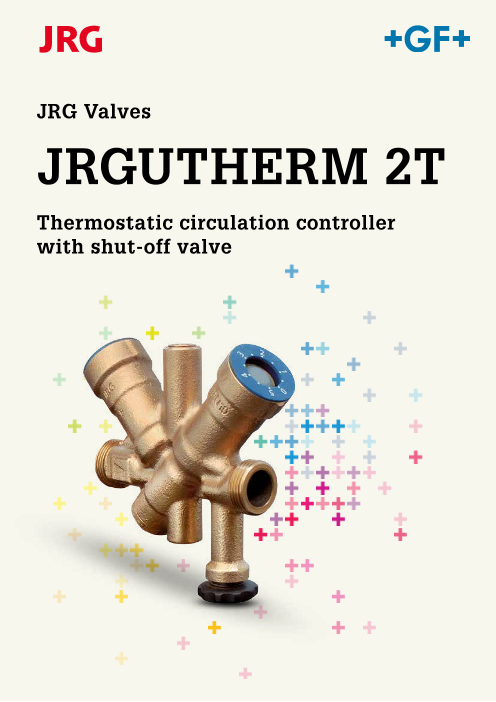


JRGUTHERM 2T - Thermostatic circulation controller with shut-off valve
製品カタログ
Advantages
・Simple flow calculations
・No setting-up calculations
・Two temperatures, two thermostats
・Automatic hydraulic balance, thermostatically controlled
・Energy saving thanks to minute balance
・Controlled through seat valve
・Large temperature setting range
・Operates without external power
・Basic volume bore exchangeable
・Basic volume bore inactive during disinfection
このカタログについて
| ドキュメント名 | JRGUTHERM 2T - Thermostatic circulation controller with shut-off valve |
|---|---|
| ドキュメント種別 | 製品カタログ |
| ファイルサイズ | 1Mb |
| 取り扱い企業 | ジョージフィッシャー株式会社 (この企業の取り扱いカタログ一覧) |
この企業の関連カタログ


このカタログの内容
Page1
JRG Valves
JRGUTHERM 2T
Thermostatic circulation controller
with shut-off valve
Page2
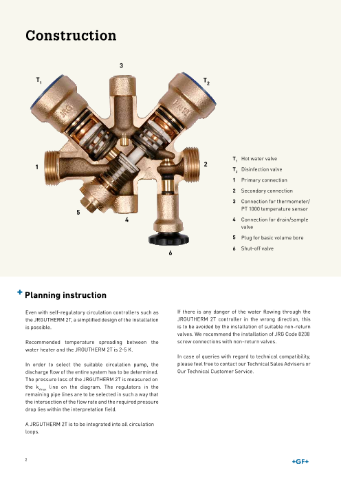
Construction
3
T1 T2
T1 Hot water valve
1 2 T2 Disinfection valve
1 Primary connection
2 Secondary connection
3 Connection for thermometer/
PT 1000 temperature sensor
5
4 4 Connection for drain/sample
valve
5 Plug for basic volume bore
6 Shut-off valve
6
P lanning instruction
Even with self-regulatory circulation controllers such as If there is any danger of the water flowing through the
the JRGUTHERM 2T, a simplified design of the installation JRGUTHERM 2T controller in the wrong direction, this
is possible. is to be avoided by the installation of suitable non-return
valves. We recommend the installation of JRG Code 8208
Recommended temperature spreading between the screw connections with non-return valves.
water heater and the JRGUTHERM 2T is 2-5 K.
In case of queries with regard to technical compatibility,
In order to select the suitable circulation pump, the please feel free to contact our Technical Sales Advisers or
discharge flow of the entire system has to be determined. Our Technical Customer Service.
The pressure loss of the JRGUTHERM 2T is measured on
the kVmax line on the diagram. The regulators in the
remaining pipe lines are to be selected in such a way that
the intersection of the flow rate and the required pressure
drop lies within the interpretation field.
A JRGUTHERM 2T is to be integrated into all circulation
loops.
2
Page3
Function A dvantages
The JRGUTHERM 2T circulation controller regulates
the volume flow in normal as well as in disinfection
•
operation mode by permanently sensing the water Simple flow calculations
•
temperature with a thermostat. Hydraulic calibration No setting-up calculations
•
is automatically effected through thermal calibration. Two temperatures, two thermostats
• Automatic hydraulic balance, thermostatically controlled
•
Materials Energy saving thanks to minute balance
•
All water-bearing parts are made of gunmetal, copper, Controlled through seat valve
•
stainless steel or high quality plastic, seals are made of Large temperature setting range
•
EPDM. Operates without external power
• Basic volume bore exchangeable
•
Installation position Basic volume bore inactive during disinfection
The JRGUTHERM 2T circulation controller can be instal-
led in any position. By using the appropriate threaded
shut-off valves, non-return and shut-off valves can be
directly integrated.
For revision purposes, we recommend installing shutoff
valves, JRG Code 8339, before and after the circulation
controller.
Area of application
The JRGUTHERM 2T is a thermostatic circulation control-
ler for heated drinking water which regulates circulation
in normal as well as in disinfection operation mode.
Setting range T1
(hot water temperature) 35-60°C
Setting range T2 Skala 0-5
(disinfection temperature) (≈70-75°C)
Maximum temperature load 90°C
Maximum operating pressure PN 10
40 kPa
Maximum differential pressure (0,4 bar)
The JRGUTHERM 2T flow regulator is protected from
over-heating.
The circulation controller may not be used in gravity
circulation systems.
Certification pending.
Technical changes remain reserved at all times.
3
Page4
Control characteristics
T [°C] K 3V [m /h]
KV max 1.0
KV max 0.85
T Water heaterlead time
T JRGUTHERM 2Tactual
KV actual
KV-value
KV min 0.1 KV min 0t [min]
Phase 1 Phase 2 Phase 3 Phase 4
T1 Basic volume T2
Operating phases
Control characteristics with factory-set target temperature:
T1-hot water temperature 58°C (range: 35-60°C)
T2-disinfection 70°C (range: 70-75°C)
Operating
phases Description of control characteristics
1 The hot water temperature is controlled. The thermostat T1 regulates the calibration temperature
according to factory-set value of 58°C.
2 An increased hot water temperature supply to the JRGUTHERM 2T triggers a disinfection.
3 With factory settings the conversion is started at 66°C, the valve temporarily opens to the maximum KV
value T2. Disinfection starts and the calibration.
4 The disinfection temperature is set according to the pre-set calibration temperature T2. Heat output
and the required amount of water are coordinated and thus the thermal calibration is automatically
controlled. The basic bore is set to inactive and the water volume is reduced to the required volume
flow.
4
Temperature
Operating range
Operating range
Volume flow or
pressure difference
Page5
Nomogram
KV-range T1
0.1 m3/h T = 0.85 m3/h T = 1.0 m3/h
1000 2 1
K min £ 0.1 m3V /h KV max T
3
1 = 1.0 m /h
100
10
10 100 1000
Circulation flow volume [l/h]
5
Pressure difference [mbar]
Recommended operating conditions
Page6
Installation example
Upper distribution Pipe on pipe Conventional
V < 3 l
m3
m3
V < 3 l
Single circulation
DIN Text JRG Code
TWK – Cold water – WKR
TWW – Hot water – WWV
TWZ – circulation WW – WWR
Stop valve 5200-34
Non-return valve 1610-15
Swing check valve 1682
Adjustable socket 6310
JRGUTHERM 2T circulation controller 6325
Circulation pump
Drain valve 6000-12
Circulation collector
Water meter 5450 m3
Ball valve 6020/23
6
Page7
JRGUTHERM 2T/Accessories
JRGUTHERM 2T Circulation Controller, PN 10
• Temperature: max. 90°C
• Material: gunmetal
• Connection: male thread
GN DN JRG GF Weight
(inch) (mm) Code Code (kg)
1∕2 15 6325.015 350 831 421 1.033
3∕4 20 6325.020 350 831 422 1.110
GN DN b1 d1 G d2 h1 h2 h3 l1 l2 l3 l4 l5 l6 ⎔
(inch) (mm) (mm) (inch) (inch) (mm) (mm) (mm) (mm) (mm) (mm) (mm) (mm) (mm)
1∕2 15 37 3∕ 14 ∕4 64 57 33 110 6 57 260 82 61 4
3∕4 20 37 1 1∕4 64 57 33 123 7 64 260 82 61 4
Thermometer
• Description: to 3500, 3510, 6325
• Material: stainless steel
GN DN JRG GF Weight d d1 G l1 l2 ⎔
(inch) (mm) Code Code (kg) (mm) (inch) (mm) (mm)
1∕4 8 8349.080 350 830 191 0.080 52 1∕4 19 35 17
Temperature sensor PT 1000, PN 10
• Temperature: max. 0 - 105°C
GN DN JRG GF Weight d1 G l1 l2 ⎔
(inch) (mm) Code Code (kg) (inch) (mm) (mm)
1∕4 8 6326.001 350 830 182 0.072 1∕4 46 1000 16
7
Page8
Accessories/Unions
Thermometer
• Description: to 8348.080
• Material: brass, plastic
d JRG GF Weight d1 l1
(mm) Code Code (kg) (mm) (mm)
52 8348.001 350 830 194 0.030 9 62
Sleeve
• Description: to 8348.001
• Material: stainless steel, EPDM
GN JRG GF Weight d1 G d2 l1 l2 ⎔
(inch) Code Code (kg) (inch) (mm) (mm) (mm)
1∕4 8348.080 350 830 192 0.030 1∕4 9 15 35 13
JRG LegioStop Drain cock, PN 16
• Temperature: max. 90°C (adjustable to 45°C)
• Material: brass
• Connection: male thread
* to 5120
GN DN JRG GF Weight d1 R d2 d3 h l l1 l2
(inch) (mm) Code Code (kg) (inch) (mm) (mm) (mm) (mm) (mm) (mm)
1∕4 8 7301.080 350 896 020 0.053 1∕4 30 14 45 46 25 38
8
Page9
Accessories/Unions
Sampling valve, PN 16
• Description: for microbiological water analysis with temperature indicator
• Temperature: max. 90°C
• Material: gunmetal, stainless steel, EPDM
• Connection: male thread
GN DN JRG GF Weight
(inch) (mm) Code Code (kg)
1∕4 8 7306.080 351 110 365 0.190
GN DN d1 R d3 h l l1 l2 ⎔1 ⎔3 ⎔2
(inch) (mm) (inch) (mm) (mm) (mm) (mm) (mm)
1∕4 8 1∕4 8 65 35 16 125 20 14 5
Union, PN 10
• Description: to 3600, 6320, 6325
• Temperature: max. 90°C
• Connection: female thread
• Consisting of: ball valve, lockable, loose nut
GN DN JRG GF Weight d1 Rp d2 G l ⎔1 ⎔2 ⎔3 z
(inch) (mm) Code Code (kg) (inch) (inch) (mm) (mm)
1∕2 15 8339.240 350 887 710 0.170 1∕ 32 ∕4 55 30 27 6 43
3∕4 20 8339.320 350 887 911 0.260 3∕4 1 55 37 32 6 47
Union with non return valve
• Material: brass, plastic, EPDM
• Connection: male thread
GN DN JRG GF Weight d1 R d2 G l l1 l2 z ⎔1 ⎔2
(inch) (mm) Code Code (kg) (inch) (inch) (mm) (mm) (mm) (mm)
1∕2 15 8208.240 351 055 901 0.090 1∕ 32 ∕4 40 34 6 19 30 19
3∕4 20 8208.320 351 056 001 0.150 3∕4 1 44 37 7 20 37 24
9
Page10
Adjustment/Setting ranges
Setting up the circulation controller Adjusting the circulation controller
In principle, all circulation controllers built into the Changing the factory settings is at the sole responsibility
system must be adjusted to the same values. of the performer.
A stepless adjustment is possible. The factory settings of the JRGUTHERM 2T circulation
The adjustment values are shown in the tables 1 and 2. controller can be changed as follows:
The individual circulation lines are automatically Remove the sealing cap and apply Allen key to the respec-
calibrated. tive hexagon socket – either T1 for hot water temperature
or T2 for disinfection temperature.
Transport packaging Turn the key clockwise to reduce and turn it counter-
clockwise to increase the temperature.
Don’t exceed the stop (minimum/maximum) when adjus-
ting the temperature.
After installation and adjustment, the transport packa-
ging of the JRGUTHERM 2T circulation controller is used
as thermal insulation.
• Thermal conductivity D = 0.033 W/mK
• Fire behavior (BKZ) 5.1/B1
• Application temperature ≤ 90°C
10
Page11
Adjustment/Setting ranges
Setting ranges
Table 1: Calibration temperature T1 (hot water)
Minimal water temperature Maximal water temperature
Setting [°C] water heater [°C] water heater [°C]
35 38 40
40 43 45
45 48 50
50 53 55
55 58 60
58 (factory setting) 61 63
60 63 65
Table 2: Calibration temperature T2 (thermal disinfection)
Corresponds to disinfection Start temperature Minimal water temperature
Scale setting temperature [°C] disinfection [°C] water heater [°C]
0 (factory setting) ~ 70 66 ³ 75
1 ~ 71 67 ³ 76
2 ~ 72 68 ³ 77
3 ~ 73 69 ³ 78
4 ~ 74 70 ³ 79
5 ~ 75 71 ³ 80
Maintenance
• The JRGUTHERM 2T is maintenance-free.
• The mounting and operating instruction delivered with
the valve, has to be handed over to the building owner.
11
Page12
GF Piping Systems
Worldwide at home
Our sales companies and representatives
ensure local customer support in over 100 countries.
www.gfps.com
Argentina / Southern South America France Middle East Spain / Portugal
Georg Fischer Central Plastics Sudamérica S.R.L. Georg Fischer SAS Georg Fischer Piping Systems (Switzerland) Ltd Georg Fischer S.A.
Buenos Aires, Argentina 95932 Roissy Charles de Gaulle Cedex Dubai, United Arab Emirates 28046 Madrid
Phone +54 11 4512 02 90 Phone +33 (0) 1 41 84 68 84 Phone +971 4 289 49 60 Phone +34 (0) 91 781 98 90
Fax +54 11 4512 02 93 Fax. +33 (0) 1 41 84 68 85 Fax +971 4 289 49 57 Fax +34 (0) 91 426 08 23
gfcentral.ps.ar@georgfischer.com fr.ps@georgfischer.com gss.ps@georgfischer.com es.ps@georgfischer.com
www.gfps.com/ar www.gfps.com/fr www.gfps.com/int www.gfps.com/es
Australia Germany Netherlands Sweden
George Fischer Pty Ltd Georg Fischer GmbH Georg Fischer N.V. Georg Fischer AB
Riverwood NSW 2210 73095 Albershausen 8161 PA Epe 11743 Stockholm
Phone +61 (0) 2 9502 8000 Phone +49 (0) 7161 302 0 Phone +31 (0) 578 678 222 Phone +46 (0) 8 506 77 50 0
Fax +61 (0) 2 9502 8090 Fax +49 (0) 7161 302 25 9 Fax +31 (0) 578 621 768 Fax +46 (0) 8 749 23 70
australia.ps@georgfischer.com info.de.ps@georgfischer.com nl.ps@georgfischer.com info.se.ps@georgfischer.com
www.gfps.com/au www.gfps.com/de www.gfps.com/nl www.gfps.com/se
Austria India New Zealand Switzerland
Georg Fischer Rohrleitungssysteme GmbH Georg Fischer Piping Systems Pvt. Ltd. Georg Fischer Ltd Georg Fischer Rohrleitungssysteme (Schweiz) AG
3130 Herzogenburg 400 076 Powai, Mumbai 5140 Upper Hutt 8201 Schaffhausen
Phone +43 (0) 2782 856 43 0 Phone +91 22 4007 2000 Phone +64 (0) 4 527 9813 Phone +41 (0)52 631 3026
Fax +43 (0) 2782 856 64 Fax +91 22 4007 2020 Fax +64 (0) 4 527 9834 Fax +41 (0)52 631 2800
austria.ps@georgfischer.com branchoffice@georgfischer.com nz.ps@georgfischer.com ch.ps@georgfischer.com
www.gfps.com/at www.gfps.com/in www.gfps.com/nz www.gfps.com/ch
Belgium / Luxembourg Indonesia Norway Taiwan
Georg Fischer NV/SA George Fischer Pte Ltd Georg Fischer AS Georg Fischer Co. Ltd.
1600 Sint-Pieters-Leeuw / Belgium 41371 Jawa Barat 1351 Rud 24158 New Taipei City
Phone +32 (0) 2 556 40 20 Phone +62 267 432 044 Phone +47 67 18 29 00 Phone +886 2 8512 2822
Fax +32 (0) 2 524 34 26 Fax +62 267 431 857 Fax +47 67 13 92 92 Fax +886 2 8512 2823
be.ps@georgfischer.com indonesia.ps@georgfischer.com no.ps@georgfischer.com tw@georgfischer.com
www.gfps.com/be www.gfps.com/id www.gfps.com/no www.gfps.com/tw
Brazil Italy Philippines Turkey
Georg Fischer Sist. de Tub. Ltda. Georg Fischer S.p.A. George Fischer Representative Office Georg Fischer Hakan Plastik
04571-020 São Paulo/SP 20063 Cernusco S/N (MI) 1604 Pasig City Boru ve Profil San. Tic. A.S.
Phone +55 (0) 11 5525 1311 Phone +39 02 921 86 1 Phone +632 571 2365 59500 Cerkezkoy / Tekirdag
br.ps@georgfischer.com Fax +39 02 921 86 24 7 Fax +632 571 2368 Phone +90 282 726 64 43
www.gfps.com/br it.ps@georgfischer.com sgp.ps@georgfischer.com Fax +90 282 726 94 67
www.gfps.com/it www.gfps.com/sg hpsales@hakan.com.tr
Canada www.hakan.com.tr
Georg Fischer Piping Systems Ltd Japan Poland
Mississauga, ON L5T 2B2 Georg Fischer Ltd Georg Fischer Sp. z o.o. United Kingdom / Ireland
Phone +1 (905) 670 8005 530-0003 Osaka 05 090 Sekocin Nowy George Fischer Sales Ltd
Fax +1 (905) 670 8513 Phone +81 (0) 6 6341 2451 Phone +48 (0) 22 3131 050 CV2 2ST Coventry, United Kingdom
ca.ps@georgfischer.com jp.ps@georgfischer.com Fax +48 (0) 22 3131 060 Phone +44 (0) 2476 535 535
www.gfps.com/ca www.gfps.com/jp poland.ps@georgfischer.com Fax +44 (0) 2476 530 450
www.gfps.com/pl uk.ps@georgfischer.com
China Korea www.gfps.com/uk
Georg Fischer P iping Systems Ltd Georg Fischer Piping Systems Romania
201319 Shanghai 463-824 Seoul Georg Fischer Rohrleitungssysteme (Elvetia) USA /Caribbean
Phone +86 21 3899 3899 Phone +82 31 8017 1450 3 S.A. SUCURSALA BUCURESTI Georg Fischer LLC
Fax +86 21 3899 3888 Fax +82 31 8017 1454 020257 Bucuresti 92618 Irvine
china.ps@georgfischer.com kor.ps@georgfischer.com Phone +40 311 040 492 Phone +1 714 731 88 00
www.gfps.com/cn www.gfps.com/kr Fax +40 212 317 479 Fax +1 714 731 62 01
ro.ps@georgfischer.com Toll Free 800/854 40 90
Denmark / Iceland Malaysia www.gfps.com/int us.ps@georgfischer.com
Georg Fischer A/S George Fischer (M) Sdn. Bhd. www.gfps.com/us
2630 Taastrup, Denmark 40460 Shah Alam, Selangor Darul Ehsan Russia
Phone +45 (0) 7022 1975 Phone +60 (0) 3 5122 5585 Georg Fischer Piping Systems (Switzerland) Ltd International
Fax +45 (0) 7022 1976 Fax +60 (0) 3 5122 5575 Moscow Representative Office Georg Fischer Piping Systems (Switzerland) Ltd
info.dk.ps@georgfischer.com my.ps@georgfischer.com 125040 Moscow 8201 Schaffhausen
www.gfps.com/dk www.gfps.com/my Phone +7 495 748 11 44 Phone +41 (0) 52 631 3003
ru.ps@georgfischer.com Fax +41 (0) 52 631 2893
Finland Mexico / Northern Latin America www.gfps.com/ru info.export@georgfischer.com
Georg Fischer AB Georg Fischer S.A. de C.V. www.gfps.com/int
01510 Vantaa Apodaca, Nuevo Leon, Mexico Singapore
Phone +358 (0) 9 586 58 25 Phone +52 (81) 1340 8586 George Fischer Pte Ltd
Fax +358 (0) 9 586 58 29 Fax +52 (81) 1522 8906 528 872 Singapore
info.fi.ps@georgfischer.com mx.ps@georgfischer.com Phone +65 6747 0611
www.gfps.com/fi www.gfps.com/mx Fax +65 6747 05 77
sgp.ps@georgfischer.com
www.gfps.com/sg
The technical data are not binding. They neither constitute expressly 37 251 62
warranted characteristics nor guaranteed properties nor a guaranteed durability. 1 / 08.17
They are subject to modification. Our General Terms of Sale apply.
© Georg Fischer JRG AG
Hauptstrasse 130
CH-4450 Sissach/Switzerland
Telefon +41 (0) 61 975 22 22
info.jrg.ps@georgfischer.com
Printed in Switzerland