


Safe and fast installation
The well-proven JRGUSIT distribution valve has now been available for more than 30 years. Today’s technical challenges call for streamlined installation times. That is the reason why we have developed the new “JRGUSIT NG”, which does not only comply with highest hygienic standards, but is also very durable thanks to the top-grade materials used. The preassembled unions reduce the time required for sealing on site thus saving more than 50 % of installation time.
このカタログについて
| ドキュメント名 | JRGUSIT NG - Distribution valve |
|---|---|
| ドキュメント種別 | 製品カタログ |
| ファイルサイズ | 1.9Mb |
| 取り扱い企業 | ジョージフィッシャー株式会社 (この企業の取り扱いカタログ一覧) |
この企業の関連カタログ


このカタログの内容
Page1
JRG Valves
JRGUSIT NG
Distribution valve
Page2
JRGUSIT NG distribution valve
Safe and fast
installation
The well-proven JRGUSIT distribution valve has now been available for more than 30 years.
Today’s technical challenges call for streamlined installation times. That is the reason
why we have developed the new “JRGUSIT NG”, which does not only comply with highest
hygienic standards, but is also very durable thanks to the top-grade materials used. The
preassembled unions reduce the time required for sealing on site thus saving more than
50 % of installation time.
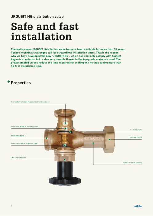
P roperties
Connection for drain valve (on both sides, closed)
Valve seat made of stainless steel
Gasket (EPDM)
Male thread (BR 1)
Loose nut (BR 1)
Valve rod made of stainless steel
JRG LegioStop top
Gunmetal valve housing
2
Page3
The new generation JRGUSIT NG is designed to be used as Advantages
distributor as well as collector. The distribution valve comes
with a threaded connection on both sides for a drain valve. • Time saving thanks to fast installation
The connections are delivered closed with a plug. • Modular system, highly versatile
• No need for sealing
Thanks to the modular character of the valve and sizes of the • Low pressure drop on outlet
main ranging from DN25 to DN65, we are able to provide • Top in water pockets free design ensuring long-lasting,
solutions for single and multi-family homes as well as larger smooth performance
objects. • Use as distributor or collector
The valves meet strict hygienic standards due to their
compact design and the use of dead space free tops, which
additionally ensures a long-lasting, smooth operation.
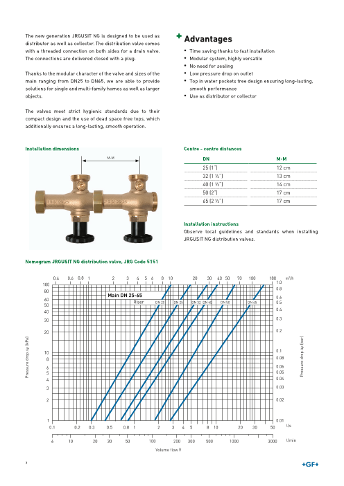
Installation dimensions Centre - centre distances
M-M DN M-M
25 (1“) 12 cm
32 (1 ¼“) 13 cm
40 (1 ½“) 14 cm
50 (2“) 17 cm
65 (2 ½“) 17 cm
Installation instructions
Observe local guidelines and standards when installing
JRGUSIT NG distribution valves.
Nomogram JRGUSIT NG distribution valve, JRG Code 5151
m3/h 0.4 0.6 0.8 1 2 3 4 5 6 8 10 20 30 40 50 70 100 180 m3/h
100 1.0
80 0.8
Main DN 25-65
60 0.6Riser DN 20 DN 25 DN 32 DN 40 DN 50 DN 65 0.5
50
40 0.4
30 0.3
20 0.2
10 0.1
8 0.08
6 0.06
5 0.05
4 0.04
3 0.03
2 0.02
1 0.01
l/s 0.1 0.2 0.3 0.5 0.8 1 2 3 4 5 8 10 20 30 50 l/s
l/min 6 10 20 30 50 100 200 300 500 1000 3000 l/min
Volume flow V
3
Pressure drop Dr (kPa)
Pressure drop Dr (bar)
Page4
Possible installation examples of the
JRGUSIT NG distribution valve
The JRGUSIT NG distribution valve can be installed
in any position.
tested and
approved
4
Page5
JRGUSIT NG
DProidsutkrtiebutuion valve JRGUSIT NG
Distribution valve JRGUSIT NG JRG LegioStop, PN 16
Internally/externally threaded stem and externally threaded outlet BR 1 according to EN ISO
228-1, without screw connection, PN 16, with free of death traps and maintenance-free top JRG
LegioStop.
Made of gunmetal, grinded non-rising valve stem and seat made of stainless steel, EPDM seals,
plastic handwheel.
For water up to 90°C.
Shut-off valve top 5158, drain valve 7301.080
Screw connections for outlet 4700, 5178, 8333, 8350, 8355
GN DN JRG GF Weight
(inch) (mm) Code Code (kg)
1 - 3∕4 25 - 20 5151.100 350 835 220 0.750
1 - 1 25 - 25 5151.110 350 835 320 0.900
1 1∕4 - 3∕4 32 - 20 5151.200 350 835 420 0.850
1 1∕4 - 1 32 - 25 5151.210 350 835 520 1.000
1 1∕4 - 1 1∕4 32 - 32 5151.220 350 835 620 1.150
1 1∕ - 32 ∕4 40 - 20 5151.300 350 835 720 0.950
1 1∕2 - 1 40 - 25 5151.310 350 835 820 1.100
1 1∕2 - 1 1∕4 40 - 32 5151.320 350 835 920 1.250
1 1∕2 - 1 1∕2 40 - 40 5151.330 350 836 020 1.500
GN DN d1 G d2 G d3 G d4 G d5 Rp d6 h1 h2 h3 l1 l2 l3
(inch) (mm) (inch) (inch) (inch) (inch) (inch) (mm) (mm) (mm) (mm) (mm) (mm) (mm)
1 - 3∕4 25 - 20 1 1∕4 1 1∕ 3 14 1 ∕4 ∕4 53 85 55 7 128 37 8
1 - 1 25 - 25 1 1∕ 1 14 ∕4 1 1∕ 14 1 ∕4 60 87 55 8 128 37 8
1 1∕ - 3∕ 32 - 20 1 1∕ 1 14 4 2 ∕2 1 3∕ 14 ∕4 53 85 56 7 139 42 9
1 1∕4 - 1 32 - 25 1 1∕2 1 1∕ 1 12 ∕ 14 1 ∕4 60 87 56 8 139 42 9
1 1∕ - 1 1∕ 32 - 32 1 14 4 ∕ 12 1 ∕ 1 12 ∕2 1 1∕ 14 ∕4 70 91 56 9 139 42 9
1 1∕ - 3∕ 40 - 20 1 32 4 ∕ 34 1 ∕4 1 3∕ 14 ∕4 53 85 57 7 150 45 10
1 1∕2 - 1 40 - 25 1 3∕ 1 34 ∕4 1 1∕4 1 1∕4 60 87 57 8 150 45 10
1 1∕2 - 1 1∕4 40 - 32 1 3∕ 1 34 ∕4 1 1∕ 1 12 ∕ 14 ∕4 70 91 57 9 150 45 10
1 1∕2 - 1 1∕ 40 - 40 1 3∕ 1 3 3 1 12 4 ∕4 1 ∕4 1 ∕2 ∕4 90 97 57 10 150 45 10
GN DN l4 z ⎔
(inch) (mm) (mm) (mm)
1 - 3∕4 25 - 20 8 83 6
1 - 1 25 - 25 8 83 6
1 1∕4 - 3∕4 32 - 20 9 89 6
1 1∕4 - 1 32 - 25 9 89 6
1 1∕4 - 1 1∕4 32 - 32 9 89 6
1 1∕ - 32 ∕4 40 - 20 10 96 6
1 1∕2 - 1 40 - 25 10 96 6
1 1∕2 - 1 1∕4 40 - 32 10 96 6
1 1∕2 - 1 1∕2 40 - 40 10 96 6
5
Page6
Distributuion valve JRGUSIT NG
Distribution valve JRGUSIT NG JRG LegioStop, PN 16
Internally/externally threaded stem and externally threaded outlet BR 1 according to EN ISO
228-1, without screw connection, PN 16, with free of death traps and maintenance-free top JRG
LegioStop.
Made of gunmetal, grinded non-rising valve stem and seat made of stainless steel, EPDM seals,
plastic handwheel.
For water up to 90°C.
Shut-off valve top 5158, drain valve 7301.080
S crew connections for outlet 4700, 5178, 8333, 8350, 8355
GN DN JRG GF Weight
(inch) (mm) Code Code (kg)
2 - 3∕4 50 - 20 5151.400 350 836 120 1.500
2 - 1 50 - 25 5151.410 350 836 220 1.700
2 - 1 1∕4 50 - 32 5151.420 350 836 320 1.800
2 - 1 1∕2 50 - 40 5151.430 350 836 420 2.100
2 - 2 50 - 50 5151.440 350 836 520 2.200
2 1∕2 - 1 65 - 25 5151.500 350 836 620 2.390
2 1∕ 12 - 1 ∕4 65 - 32 5151.510 350 836 720 2.600
2 1∕2 - 1 1∕2 65 - 40 5151.520 350 836 820 2.850
2 1∕2 - 2 65 - 50 5151.530 350 836 920 2.975
2 1∕ - 2 12 ∕2 65 - 65 5151.540 350 837 020 3.735
GN DN d1 G d2 G d3 G d4 G d5 Rp d6 h1 h2 h3 l1 l2 l3
(inch) (mm) (inch) (inch) (inch) (inch) (inch) (mm) (mm) (mm) (mm) (mm) (mm) (mm)
2 - 3∕4 50 - 20 2 3∕ 3 3 18 2 ∕8 1 ∕4 ∕4 53 98 65 7 181 54 11
2 - 1 50 - 25 2 3∕ 38 2 ∕8 1 1∕ 1 14 ∕4 60 100 65 8 181 54 11
2 - 1 1∕4 50 - 32 2 3∕ 38 2 ∕8 1 1∕ 1 12 1 ∕4 ∕4 70 104 65 9 181 54 11
2 - 1 1∕ 50 - 40 2 3∕ 2 3∕ 32 8 8 1 ∕4 1 1∕ 12 ∕4 90 110 65 10 181 54 11
2 - 2 50 - 50 2 3∕8 2 3∕8 2 3∕ 18 2 ∕4 90 110 65 11 181 54 11
2 1∕2 - 1 65 - 25 3 3 1 1∕ 1 14 ∕4 60 108 78 8 185 67 15
2 1∕ 12 - 1 ∕4 65 - 32 3 3 1 1∕ 12 1 ∕ 14 ∕4 70 112 78 9 185 67 15
2 1∕2 - 1 1∕2 65 - 40 3 3 1 3∕4 1 1∕ 12 ∕4 90 118 78 10 185 67 15
2 1∕2 - 2 65 - 50 3 3 2 3∕ 18 2 ∕4 90 118 78 11 185 67 15
2 1∕ 12 - 2 ∕2 65 - 65 3 3 3 2 1∕ 12 ∕4 120 138 78 15 185 67 15
GN DN l4 z ⎔
(inch) (mm) (mm) (mm)
2 - 3∕4 50 - 20 11 116 6
2 - 1 50 - 25 11 116 6
2 - 1 1∕4 50 - 32 11 116 6
2 - 1 1∕2 50 - 40 11 116 6
2 - 2 50 - 50 11 116 6
2 1∕2 - 1 65 - 25 15 104 6
2 1∕2 - 1 1∕4 65 - 32 15 104 6
2 1∕2 - 1 1∕2 65 - 40 15 104 6
2 1∕2 - 2 65 - 50 15 104 6
2 1∕2 - 2 1∕2 65 - 65 15 104 6
6
Page7
Overview unions/adapters
4700 8201 8204 8205 8209 8331 8333 8350 8355 5178 iFIT INSTAFLEX
Valves/Dimensions DN 20 DN 25 DN 32 DN 40 DN 50 DN 65
Thread Size G 1 G 1¼ G 1½ G 1¾ G 2 3/8 G 3
Adapters
Threaded union
JRG Code 8201.320 (¾“) 8201.400 (1“) 8201.480 (1¼“) 8201.560 (1½“) 8201.640 (2“) 8201.720 (2½“)
Threaded union 8209.022 (22) 8209.122 (22)
JRG Code 8205.022 (22) 8205.028 (28) 8209.028 (28) 8205.042 (42) 8205.154 (54) -8205.035 (35)
8204.320 (¾“) 8204.400 (1“)
Threaded union 8299.320 (¾“) 8299.400 (1“) 8299.480 (1¼“)
JRG Code 8333.320 (¾“) 8331.320 (¾“) 8331.322 (¾“)
8299.560 (1½“) 8299.640 (2“) 8299.720 (2½“)
8333.400 (1“) 8333.560 (1½“) 8333.640 (2“) 8333.720 (2½“)8333.400 (1“) 8333.480 (1¼“)
Sleeve union
JRG Code 5178.320 (1“) 5178.400 (1¼“) 5178.480 (1½“) 5178.560 (1¾“) 5178.640 (2
3/8“) 5178.720 (3“)
Plastic adapters
JRG Sanipex MT 4700.108 (16)
JRG Code 4700.110 (20) 4700.126 (32) 4700.132 (40) 4700.134 (50) 4700.140 (63) -4700.112 (26)
Georg Fischer iFIT 762101282 762101283 462101284
GF Code (25/32) (25/32) (25/32) - - -
Georg Fischer INSTAFLEX 761069686 (20) 761069689 (25)
GF Code 761069688 (25) 761069691 (32)
761069692 (32) 761069696 (50) 761069698 (63) -
761069690 (32) 761069693 (40) 761069694 (40)
Unions with press socket
Geberit Mapress 8351.018 (18) 8351.122 (22)
JRG Code 8350.022 (22) 8351.022 (22) 8351.028 (28) 8350.042 (42) 8350.054 (54) -8350.028 (28) 8350.035 (35)
Viega Sanpress/Nussbaum 8356.018 (18) 8356.122 (22)
Optipress JRG Code 8355.022 (22) 8356.022 (22) 8356.028 (28) 8355.042 (42) 8355.054 (54) -8356.028 (28) 8355.035 (35)
AFM 34 gaskets and EPDM profiled gaskets must not be oiled or greased.
7
Page8
UVenrsichornausb/uangdenapters
Adapter with male thread
With external thread BR 1 to EN ISO 228-1, made of gunmetal.
GN DN JRG GF Weight d1 G d2 R l1 l2
(inch) (mm) Code Code (kg) (inch) (inch) (mm) (mm)
1 25 5170.400 350 895 060 0.180 1 1∕4 1 45 7
1 1∕4 32 5170.480 350 895 160 0.300 1 1∕ 12 1 ∕4 48 8
1 1∕2 40 5170.560 350 895 260 0.300 1 3∕ 14 1 ∕2 51 9
2 50 5170.640 350 895 360 0.500 2 3∕8 2 57 10
2 1∕2 65 5170.720 350 895 460 0.900 3 2 1∕2 64 14
Adapter with female thread
With external thread BR 1 to EN ISO 228-1, made of gunmetal.
GN DN JRG GF Weight d1 G d2 Rp l1 l2 z
(inch) (mm) Code Code (kg) (inch) (inch) (mm) (mm) (mm)
1 25 5171.400 350 895 061 0.200 1 1∕4 1 36 7 19
1 1∕2 40 5171.560 350 895 261 0.300 1 3∕ 14 1 ∕2 40 9 21
2 50 5171.640 350 895 361 0.550 2 3∕8 2 46 10 23
2 1∕2 65 5171.720 350 895 461 1.460 3 2 1∕2 52 14 25
1 1∕4 32 5171.480 350 895 161 0.250 1 1∕ 12 1 ∕4 38 8 19
Sleeve connection
With internal thread BR 1 to EN ISO 228-1, made of gunmetal.
DN JRG GF Weight d1 G l1 l2 l3 z
(mm) Code Code (kg) (inch) (mm) (mm) (mm) (mm)
20 5178.320 350 894 968 0.175 1 46 7 14 32
25 5178.400 350 895 068 0.300 1 1∕4 51 8 15 35
32 5178.480 350 895 168 0.450 1 1∕2 55 9 16 37
40 5178.560 350 895 268 0.500 1 3∕4 59 10 17 39
50 5178.640 350 895 368 1.000 2 3∕8 68 11 20 46
65 5178.720 350 895 468 1.600 3 81 15 24 52
Union with male thread
Made of brass, with conical male thread and gasket suitable to 1300-1333, 1350-1363, 1370,
1371, 1840, 2100-2110, 2113, 2130-2140, 2143, 8201.402 suitable to 9601.040, 9603.040,
9606.040, 9695.480
GN DN JRG GF Weight d1 R d2 G l1 l2
(inch) (mm) Code Code (kg) (inch) (inch) (mm) (mm)
3∕4 20 8201.320 350 331 801 0.100 3∕4 1 29 7
1 25 8201.400 350 331 901 0.180 1 1 1∕4 34 8
1 1∕4 32 8201.480 350 332 001 0.290 1 1∕ 14 1 ∕2 38 9
1 1∕2 40 8201.560 350 332 101 0.360 1 1∕2 1 3∕4 39 10
2 50 8201.640 350 332 201 0.620 2 2 3∕8 47 11
2 1∕2 65 8201.720 350 330 901 1.350 2 1∕2 3 56 15
8
Page9
Unions/adapters
Flange adapter set
With external thread of screw connection.
Made of gunmetal, backing flange made of PP with steel ring, according SN EN 1092, with profile
flange gasket made of EPDM.
DN JRG GF Weight
(mm) Code Code (kg)
65 8231.065 350 332 465 4.540
DN d1 d2 d3 d4 d5 G l1 l2 ○ ⎔1 ⎔2
(mm) (mm) (mm) (mm) (mm) (inch) (mm) (mm)
65 185 145 122 66 3 115 32 4x18 80 85
Flange adapter set
With loose nut.
Made of gunmetal, backing flange made of PP with steel ring, according SN EN 1092, with profile
f lange gasket made of EPDM.
DN JRG GF Weight
(mm) Code Code (kg)
65 8232.065 350 332 565 4.520
DN d1 d2 d3 d4 d5 G l1 l2 z ○ ⎔1 ⎔2 ⎔3
(mm) (mm) (mm) (mm) (mm) (inch) (mm) (mm) (mm)
65 185 145 122 66 3 154 32 140 4x18 80 85 98
Union, BR 1 with female thread
Made of gunmetal, with female thread for valves with male thread according to EN ISO 228-1 and
gasket*
Suitable to: 1611, 1631, 2191, 3600, 5211, 5281, 6320, 6325
* AFM 34 gaskets cannot be oiled neither be greased
GN DN JRG GF Weight d1 Rp d2 G l z
(inch) (mm) Code Code (kg) (inch) (inch) (mm) (mm)
3∕4 20 8333.320 351 061 415 0.175 3∕4 1 52 29
1 25 8333.400 351 061 425 0.310 1 1 1∕4 59 32
1 1∕4 32 8333.480 351 061 435 0.467 1 1∕ 14 1 ∕2 65 34
1 1∕2 40 8333.560 351 061 445 0.500 1 1∕ 1 32 ∕4 68 37
2 50 8333.640 351 061 455 0.853 2 2 3∕8 77 40
2 1∕2 65 8333.720 351 061 465 1.435 2 1∕2 3 91 46
9
Page10
Unions/adapters
Adapter to valves
Adapter to valves
Made of gunmetal, with female thread and gasket*, plastic cone grip union MT for JRG Sanipex
Madde 1of6 g/udn2m0e taanl, dw iJthR fGem Saalen tihpreeaxd M anTd p giapsekest*, plastic cone grip union MT for JRG Sanipex
d16/*d A20F aMn d3 J4R Gg aSsankiepetsx MmTu psipte nsot be oiled nor greased.
* AFM 34 gaskets must not be oiled nor greased.
d GdN GN JRG JRG GF Weight dG1F G Wel1ightl2 d1l 3G z1l1 ⎔ l2 l3 z1 ⎔
(mm)(m(imnc)h) (inch) Code CodeCode (kgC) o(dinceh) (mm) (k(mg)m) (i(nmcmh)) (m(mm)m) (mm) (mm) (mm)
16 1 4700.108 351 616 936 0.135 1 42.5 7.0 35.5 22.5 37
16 1 4700.108 351 616 936 0.135 1 42.5 7.0 35.5 22.5 37
20 1 4700.110 351 620 936 0.080 1 49.0 7.0 42.0 20.5 37
26 201 47100.1124703051.1 61206 9943510 6.12150 9361 540.5.0807.0 47.51 148.95.0 377.0 42.0 20.5 37
32 216 1∕4 47100.1264703051.1 6132 9953510 6.22006 9914 1∕4 650.5.1158.0 57.51 159.45.5 467.0 47.5 18.5 37
40 1312 ∕2 14 71∕00.1324703051.1 62460 9953510 6.33302 991
1
5∕2 770.5.2009.0 618 .15∕ 24 4 63.55.5 558.0 57.5 19.5 46
50 1 3∕4 4700.134 351 650 995 0.550 1 3∕4 81.5 10.0 71.5 33.0 60
40 1 1∕ 4700.132 351 640 995 0.330 1 163 2 3∕8 47020.140 351 663 995 0.950 2 3∕8 99.5 11.0 88.5∕2 379.70.5 789.0 68.5 23.5 55
50 1 3∕4 4700.134 351 650 995 0.550 1 3∕4 81.5 10.0 71.5 33.0 60
63 2 3∕8 4700.140 351 663 995 0.950 2 3∕8 99.5 11.0 88.5 39.0 78
Adapter loose union nut - flat seal
Socket fusion transition to loose nut adapter concering
Thread in DZR brass, UBA (Umwelt Bundesamt, Germany) conform
EPDAM dseaaplitnegr h loot oansde c uolndi wonat enru atp p- rfolvaetd seal
I ncl. flat seal EPDM
Socket fusion transition to loose nut adapter concering
Thredad inG DZR brCaosdse, UWBeAig h(Ut mwLelt Bzunk dmeasxa. mL tm, iGn.e SrFmany) conform
(mm) (inch) (kg) (mm) (mm) (mm) (mm)
EPD20M se1alin7g61 h 0o6t9 a68n6d co0.l1d8 6wa1t0e7r ap9p8roved24 16
I ncl2.5 flat s1ea7l6 E1 P06D9M 688 0.200 110 102 23 20
25 1 1∕4 761 069 689 0.274 118 109 23 20
32 1d 761 0G69 690 0.2C29ode118We11ig0 ht 21 L z22 k max. L min. SF
32 (m1
1
m∕4) 7(6in1c 0h6) 9 691 0.292 118 110(kg) (m21m) (mm2)2 (mm) (mm)
32 1 1∕2 761 069 692 0.380 119 110 21 22
40 12 1∕04 761 0169 679361 006.398 6686134 010.1586 21407 9826 24 16
40 12 1∕52 761 0169 679461 006.495 8688132 012.2400 21410 10224 23 20
50 12 3∕54 7611 10∕469 6796 1 006.599 9689142 013.2174 21218 10928 23 20
63 2 33∕28 761 0169 679861 016.193 9690159 014.2729 21118 11030 21 22
32 1 1∕4 761 069 691 0.292 118 110 21 22
32 1 1∕2 761 069 692 0.380 119 110 21 22
40 1 1∕4 761 069 693 0.386 134 105 24 26
40 1 1∕2 761 069 694 0.458 132 124 24 24
50 1 3∕4 761 069 696 0.599 142 131 22 28
63 2 3∕8 761 069 698 1.139 159 147 21 30
Transition union module - flat sealed
Supplied with sealing
** on request
* low lead
d G Code Weight z
(mm) (inch) (kg) (mm)
* 25 ‐ 32 1 762 101 282 0.233 55
* 25 ‐ 32 1 1∕4 762 101 283 0.266 48
* 25 ‐ 32 1 1∕2 762 101 284 0.339 50
Transition union module - flat sealed
Supplied with sealing
** on request
* low lead10
d G Code Weight z
(mm) (inch) (kg) (mm)
* 25 ‐ 32 1 762 101 282 0.233 55
* 25 ‐ 32 1 1∕4 762 101 283 0.266 48
* 25 ‐ 32 1 1∕2 762 101 284 0.339 50
Page11
AZucbecheörssories
Sealing cap with female thread ½"
With internal thread BR 1 to EN ISO 228-1, made of gunmetal.
DN JRG GF Weight d1 G d2 G l1 ⎔
(mm) Code Code (kg) (inch) (inch) (mm)
32 5174.480 350 895 164 0.250 1 1∕ 12 ∕2 28 10
40 5174.560 350 895 264 0.350 1 3∕ 14 ∕2 30 10
50 5174.640 350 895 364 0.500 2 3∕ 18 ∕2 32 10
65 5174.720 350 895 464 0.817 3 1∕2 36 10
25 5174.400 350 895 064 0.156 1 1∕ 14 ∕2 26 10
Plug with female thread ½"
With external thread BR 1 to EN ISO 228-1, made of gunmetal.
DN JRG GF Weight d1 G d2 G l1 l2 ⎔
(mm) Code Code (kg) (inch) (inch) (mm) (mm)
25 5176.400 350 895 066 0.100 1 1∕ 14 ∕2 18 8 10
32 5176.480 350 895 166 0.150 1 1∕ 12 ∕2 19 9 10
40 5176.560 350 895 266 0.150 1 3∕ 14 ∕2 20 10 10
65 5176.720 350 895 466 0.500 3 1∕2 25 15 10
50 5176.640 350 895 366 0.250 2 3∕ 18 ∕2 21 11 10
Drain cock JRG LegioStop
With male thread, PN 16, made of brass, free of death traps. Outlet with hose coupling, adjustable
90° or 45°.
* for distribution valves JRGUSIT 5120
GN DN JRG GF Weight d1 R d2 d3 h l l1 l2
(inch) (mm) Code Code (kg) (inch) (mm) (mm) (mm) (mm) (mm) (mm)
1∕4 8 7301.080 350 896 020 0.053 1∕4 30 14 45 46 25 38
Gomito 90°
• Siliziumbronze
R / Rp Code Weight a b Za
(inch) (kg) (mm) (mm) (mm)
1∕2 768 092 004 0.150 25 32 12
Mamelon double
• Brass11
R a Code Weight
(inch) (mm) (kg)
1∕2 30 768 530 303 0.035
1∕2 40 768 530 304 0.060
1∕2 50 768 530 305 0.070
1∕2 60 768 530 306 0.075
Page12
Drain cock JRG LegioStop
With male thread, PN 16, made of brass, free of death traps. Outlet with hose coupling, adjustable
90° or 45°.
* for distribution valves JRGUSIT 5120
GN DN JRG GF Weight d1 R d2 d3 h l l1 l2
(inch) (mm) Code Code (kg) (inch) (mm) (mm) (mm) (mm) (mm) (mm)
1∕4 8 7301.080 350 896 020 0.053 1∕4 30 14 45 46 25 38
Gomito 90°
• Siliziumbronze
R / Rp Code Weight a b Za
(inch) (kg) (mm) (mm) (mm)
1∕2 768 092 004 0.150 25 32 12
Mamelon double
• Brass
R a Code Weight
(inch) (mm) (kg)
1∕2 30 768 530 303 0.035
1∕2 40 768 530 304 0.060
1∕2 50 768 530 305 0.070
1∕2 60 768 530 306 0.075
A ccessories
JRGURED pressure reducing valve without unions, PN 25 - 4 bar
Made of gunmetal, cover made of glass fibre reinforced plastic, slider and valve seat made of
stainless steel, membrane and valve seal made of EPDM, manometer connection on both sides,
sealed with 5149 plugs, stainless steel 1000 μm, transparent filter cup made of plastic. Without
unions. Factory setting 400 kPa (4 bar).
EPDM gaskets cannot be oiled neither be greased. EPDM membranes and gaskets are not suit-
able for oleaginous compressed air.
S econdary pressure 200-600 kPa (2-6 bar), Tmax 30°C
GN DN JRG GF Weight d2 G d3 Rp d4 h1 h2 l1 z ⎔
(inch) (mm) Code Code (kg) (inch) (inch) (mm) (mm) (mm) (mm) (mm)
1∕2 15 1303.015 350 712 301 0.620 3∕ 14 ∕8 54 34 79 80 40 5
3∕4 20 1303.020 350 712 401 0.770 1 1∕8 60 42 86 85 43 5
1 25 1303.025 350 712 501 1.340 1 1∕ 14 ∕4 72 52 110 100 50 6
1 1∕4 32 1303.032 350 712 601 1.800 1 1∕ 12 ∕4 80 64 121 120 60 6
1 1∕2 40 1303.040 350 712 701 3.400 1 3∕ 14 ∕4 96 80 157 145 73 8
2 50 1303.050 350 712 801 4.900 2 3∕ 18 ∕4 105 98 172 175 88 8
2 1∕2 65 1303.065 350 734 701 5.200 3 1∕4 105 98 172 180 90 8
JRGURED Combi house water station, PN 16 - 4 bar
Combined pressure reducing valve with fine filter, PN 16
Connections with male thread BR1 according EN ISO 228-1, without brass screw connections,
threaded connection for manometer valve closed with plug.
Gunmetal body, plastic cover top, slide and seat made of stainless steel, membrane and valve
gasket made of EPDM, transparent plastic filter cup with drain cock, fine filter element 100 µm,
threaded ring and key, Factory setting 4 bar. Screw connections see 8201, plug see 5149.080,
filter cup 1848/1849, fine filter element 1838/1839, fine filter key 8127.000, transparent filter
cups have to be protected from UV rays and aggressive surroundings/influences.
It’s required to use only AFM 34 gaskets.
* AFM 34 gaskets cannot be oiled neither be greased
Secondary pressure 200-600 kPa (2-6 bar), Tmax 30°C
GN DN JRG GF Weight d2 G d3 Rp d4 h1 h2 l1 z ⎔
(inch) (mm) Code Code (kg) (inch) (inch) (mm) (mm) (mm) (mm) (mm)
1 25 1353.025 350 690 501 3.950 1 1∕ 14 ∕4 122 390 110 100 50 6
1 1∕4 32 1353.032 350 690 502 4.360 1 1∕ 12 ∕4 122 393 120 120 60 6
1 1∕2 40 1353.040 350 690 503 6.100 1 3∕ 14 ∕4 130 403 157 146 73 8
2 50 1353.050 350 690 504 7.660 2 3∕ 18 ∕4 130 415 172 176 88 8
JRG CleanLine Combi, PN 16 - 4 bar
Combined pressure reducing valve with back flush fine filter, PN 16.
Male threaded connections BR 1 according to EN ISO 228-1, without unions, threaded connec-
tion for pressure gauge valve closed with plug, gunmetal housing, plastic cover top; slide, seat
and filter insert made of chrome nickel steel, EPDM valve seals and membrane, filter cup made of
transparent plastic, filter mesh 100μm, pressure reducing valve factory set at 400 kPa (4 bar).
JRG CleanLine Combi must be protected from UV radiation and aggressive environments/influ-
ences.
S econdary pressure 200-600 kPa (2-6 bar), Tmax 30°C
DN JRG GF Weight d2 G d3 Rp d4 h1 h2 l1 l2 l3 ⎔
(mm) Code Code (kg) (inch) (inch) (mm) (mm) (mm) (mm) (mm) (mm)
25 1370.025 350 690 932 3.150 1 1∕ 14 ∕4 99 221 110 100 125 60 6
32 1370.032 350 690 933 3.480 1 1∕ 12 ∕4 99 224 120 120 125 60 6
12
Page13
Accessories
JRG CleanLine Combi with automatic backwash unit PN 16 - 4 bar
Combined pressure reducing valve with backwashable fine filter, PN 16.Male threaded connec-
tions BR 1 according to EN ISO 228-1, without unions, with automatic backwash unit (100 - 240
V AC), threaded connection for pressure gauge valve closed with plug, gunmetal housing, plastic
cover top; slide, seat and filter insert made of chrome nickel steel, EPDM valve seals and mem-
brane, filter cup made of transparent plastic, filter mesh 100 µm, pressure reducing valve factory
set at 400 kPa (4bar), for water up to max 30°C. JRG CleanLine Combi must be protected from UV
radiation and aggressive environments/influences. Secondary pressure 200-600 kPa (2-6 bar),
Tmax. 30°C
DN JRG GF Weight d2 G d3 Rp d4 h1 h2 l1 l2 l3 ⎔
(mm) Code Code (kg) (inch) (inch) (mm) (mm) (mm) (mm) (mm) (mm)
25 1371.025 350 690 840 3.655 1 1∕ 14 ∕4 99 221 110 100 154 60 6
32 1371.032 350 690 841 3.990 1 1∕ 12 ∕4 99 224 120 120 154 60 6
Safety set BR 1, PN 10 - 6 bar
For water heaters of closed design, externally threaded adaptor BR1 according to EN ISO 228-1
without screw connection, PN10, with free of death traps and maintenance-free return flow in-
hibitor.
Threaded connection for test and drain valve, closed with closure plug 5149, without test and
drain valve.
Consisting of: return flow inhibitor, with sleeve connection and safety valve 1025.320.
Made of gunmetal, stainless-steel check valve seat and closing spring, PPSU baffle as plastic re-
turn flow inhibitor, EPDM seals.
For water up to 90°C.
Safety valve set to 600 kPa (6 bar).
Tested according to DIN EN 13959.
Dripping water connection for 1025 see 8223.320, check valve insert see 1628, top for 1025 see
1045.320, test and drain valve see 7301.080 and 7306.080
Unions to plastic systems: 4700, 5550. Unions to stainless steel systems: 8350, 8355. Unions to
threaded connections: 8201, 8205, 8299, 8333, 8339, 8360.
For direct connection to distributor valve, use 5178 or 8360.
It's required to use only AFM 34 gaskets.
Those cannot be oiled neither be greased.
DN JRG GF Weight
(mm) Code Code (kg)
20 1631.020 351 061 107 0.750
25 1631.025 351 061 117 1.420
32 1631.032 351 061 127 1.230
DN d1 G d2 Rp d3 G d4 Rp h2 h3 h4 h5 l1 l2 l3 z1 z2 z3 ⎔
(mm) (inch) (inch) (inch) (inch) (mm) (mm) (mm) (mm) (mm) (mm) (mm) (mm) (mm) (mm)
20 1 3∕ 34 ∕ 14 ∕4 7 32 62 37 56 77 48 24 63 17 6
25 1 1∕ 34 ∕4 1 1∕4 7 32 62 49 68 82 48 25 75 17 6
32 1 1∕ 32 ∕4 1 1∕ 14 ∕4 9 32 82 57 80 87 48 30 89 17 6
DN O-Ring
(mm)
20 09 294 21
25 09 294 04
32 09 294 05
Fine filter with by-pass JRG LegioStop
Externally threaded according EN ISO 228-1, PN 16, with free of death traps JRG LegioStop tops,
PN 16. Clear plastic filter housing, filter insert 1838 100 µm, threaded connection for pressure
gauge closed with plug 5149. Made of gunmetal, grinded non-rising valve stem and seat made
13 of stainless steel, EPDM seals, plastic handwheel, drain valve incorporated into filter. Filter cup
and filter insert for water up to max. 30°C. Plastic filter housing 1848.000, bronze filter housing
1849.000, fine filter key 8127.000. May only be installed in horizontal position, clear filter hous-
ings must be protected from UV rays and aggressive environmental influences. Filter inserts
must be replaced periodically, but at least twice a year.
GN DN JRG GF Weight d1 G d2 h1 h2 h3 l µm
(inch) (mm) Code Code (kg) (inch) (mm) (mm) (mm) (mm) (mm)
1 1∕4 25 1840.025 350 690 209 3.750 1 1∕4 122 367 102 428 228 100
1 1∕2 32 1840.032 350 690 210 4.640 1 1∕2 122 373 112 433 242 100
1 3∕4 40 1840.040 350 690 211 3.980 1 3∕4 122 376 122 436 260 100
2 3∕8 50 1840.050 350 690 212 3.980 2 3∕8 122 382 133 442 293 100
Page14
Safety set BR 1, PN 10 - 6 bar
For water heaters of closed design, externally threaded adaptor BR1 according to EN ISO 228-1
without screw connection, PN10, with free of death traps and maintenance-free return flow in-
hibitor.
Threaded connection for test and drain valve, closed with closure plug 5149, without test and
drain valve.
Consisting of: return flow inhibitor, with sleeve connection and safety valve 1025.320.
Made of gunmetal, stainless-steel check valve seat and closing spring, PPSU baffle as plastic re-
turn flow inhibitor, EPDM seals.
For water up to 90°C.
Safety valve set to 600 kPa (6 bar).
Tested according to DIN EN 13959.
Dripping water connection for 1025 see 8223.320, check valve insert see 1628, top for 1025 see
1045.320, test and drain valve see 7301.080 and 7306.080
Unions to plastic systems: 4700, 5550. Unions to stainless steel systems: 8350, 8355. Unions to
threaded connections: 8201, 8205, 8299, 8333, 8339, 8360.
For direct connection to distributor valve, use 5178 or 8360.
It's required to use only AFM 34 gaskets.
T hose cannot be oiled neither be greased.
DN JRG GF Weight
(mm) Code Code (kg)
20 1631.020 351 061 107 0.750
25 1631.025 351 061 117 1.420
32 1631.032 351 061 127 1.230
DN d1 G d2 Rp d3 G d4 Rp h2 h3 h4 h5 l1 l2 l3 z1 z2 z3 ⎔
(mm) (inch) (inch) (inch) (inch) (mm) (mm) (mm) (mm) (mm) (mm) (mm) (mm) (mm) (mm)
20 1 3∕ 34 ∕ 14 ∕4 7 32 62 37 56 77 48 24 63 17 6
25 1 1∕ 3 14 ∕4 1 ∕4 7 32 62 49 68 82 48 25 75 17 6
32 1 1∕ 32 ∕4 1 1∕ 14 ∕4 9 32 82 57 80 87 48 30 89 17 6
DN O-Ring
(mm)
20 09 294 21
25 09 294 04
Accessories32 09 294 05
Fine filter with by-pass JRG LegioStop
Externally threaded according EN ISO 228-1, PN 16, with free of death traps JRG LegioStop tops,
PN 16. Clear plastic filter housing, filter insert 1838 100 µm, threaded connection for pressure
gauge closed with plug 5149. Made of gunmetal, grinded non-rising valve stem and seat made
of stainless steel, EPDM seals, plastic handwheel, drain valve incorporated into filter. Filter cup
and filter insert for water up to max. 30°C. Plastic filter housing 1848.000, bronze filter housing
1849.000, fine filter key 8127.000. May only be installed in horizontal position, clear filter hous-
ings must be protected from UV rays and aggressive environmental influences. Filter inserts
must be replaced periodically, but at least twice a year.
GN DN JRG GF Weight d1 G d2 h1 h2 h3 l µm
(inch) (mm) Code Code (kg) (inch) (mm) (mm) (mm) (mm) (mm)
1 1∕ 14 25 1840.025 350 690 209 3.750 1 ∕4 122 367 102 428 228 100
1 1∕2 32 1840.032 350 690 210 4.640 1 1∕2 122 373 112 433 242 100
1 3∕4 40 1840.040 350 690 211 3.980 1 3∕4 122 376 122 436 260 100
2 3∕8 50 1840.050 350 690 212 3.980 2 3∕8 122 382 133 442 293 100
JRG Infinity M Filter, PN 16
Back flush fine filter manually.
Male threaded connections BR 1 according to EN ISO 228-1, without unions, connection piece
made of gunmetal, filter top made of brass, filter cup made of transparent plastic, filter mesh
100µm, for water up to max. 30°C.
J RG Infinity Filter must be protected from UV radiation and aggressive environments/influences.
GN DN JRG GF Weight
(inch) (mm) Code Code (kg)
1 1∕2 40 1880.040 350 691 012 7.100
2 50 1880.050 350 691 013 7.500
GN DN d2 G d3 Rp h1 h2 h3 l1 l2 l3 ⎔
(inch) (mm) (inch) (inch) (mm) (mm) (mm) (mm) (mm) (mm)
1 1∕2 40 1 3∕ 14 ∕4 360 500 670 145 215 152 5
2 50 2 3∕ 18 ∕4 360 500 670 175 215 152 5
JRG Infinity A Filter with automatic backwash unit, PN 16
Back flush fine filter automatically.
Male threaded connections BR 1 according to EN ISO 228-1, without unions, connection piece
made of gunmetal, filter top made of brass, filter cup made of transparent plastic, filter mesh
100µm, for water up to max. 30°C.
J RG Infinity Filter must be protected from UV radiation and aggressive environments/influences.
GN DN JRG GF Weight
(inch) (mm) Code Code (kg)
1 1∕2 40 1881.040 350 691 014 8.500
2 50 1881.050 350 691 015 8.900
GN DN d2 G d3 Rp h1 h2 h3 l1 l2 l3 ⎔
(inch) (mm) (inch) (inch) (mm) (mm) (mm) (mm) (mm) (mm)
1 1∕2 40 1 3∕ 14 ∕4 315 550 670 145 215 152 5
2 50 2 3∕ 18 ∕4 315 550 670 175 215 152 5
Double nipple
14 Made of brass, with male thread
GN DN JRG GF Weight d1 G l
(inch) (mm) Code Code (kg) (inch) (mm)
1∕2 15 8722.240 355 604 302 0.040 1∕2 24
Page15
JRG Infinity M Filter, PN 16
Back flush fine filter manually.
Male threaded connections BR 1 according to EN ISO 228-1, without unions, connection piece
made of gunmetal, filter top made of brass, filter cup made of transparent plastic, filter mesh
100µm, for water up to max. 30°C.
J RG Infinity Filter must be protected from UV radiation and aggressive environments/influences.
GN DN JRG GF Weight
(inch) (mm) Code Code (kg)
1 1∕2 40 1880.040 350 691 012 7.100
2 50 1880.050 350 691 013 7.500
GN DN d2 G d3 Rp h1 h2 h3 l1 l2 l3 ⎔
(inch) (mm) (inch) (inch) (mm) (mm) (mm) (mm) (mm) (mm)
1 1∕2 40 1 3∕ 14 ∕4 360 500 670 145 215 152 5
2 50 2 3∕ 18 ∕4 360 500 670 175 215 152 5
JRG Infinity A Filter with automatic backwash unit, PN 16
Back flush fine filter automatically.
Male threaded connections BR 1 according to EN ISO 228-1, without unions, connection piece
made of gunmetal, filter top made of brass, filter cup made of transparent plastic, filter mesh
100µm, for water up to max. 30°C.
JRG Infinity Filter must be protected from UV radiation and aggressive environments/influences.
GN DN JRG GF Weight
(inch) (mm) Code Code (kg)
1 1∕2 40 1881.040 350 691 014 8.500
2 50 1881.050 350 691 015 8.900
GN DN d2 G d3 Rp h1 h2 h3 l1 l2 l3 ⎔
(inch) (mm) (inch) (inch) (mm) (mm) (mm) (mm) (mm) (mm)
1 1∕ 3 12 40 1 ∕4 ∕4 315 550 670 145 215 152 5
Accessories 2 50 2 3∕ 18 ∕4 315 550 670 175 215 152 5
Double nipple
Made of brass, with male thread
GN DN JRG GF Weight d1 G l
(inch) (mm) Code Code (kg) (inch) (mm)
1∕2 15 8722.240 355 604 302 0.040 1∕2 24
JRG bypass mixing valve with connection piece, PN 16
Consisting of bypass, shut-off, fixed adjustable addition of untreated water and back flow preven-
ter.
Outlet with BR 1 external thread to EN ISO 228-1, without screw connection. Threaded connection
for test and drain valve closed with closure plug 5149.080, without test and drain valve.
Body made of gunmetal, seat made of stainless steel, back flow preventer made of POM, EPDM
seals, plastic handwheels.
F or water up to 65°C , for a short time 90°C.
GN DN JRG GF Weight
(inch) (mm) Code Code (kg)
1 25 5195.025 351 114 903 2.624
1 1∕4 32 5195.032 351 114 913 2.720
GN DN d1 G d2 G d3 G d4 G d5 Rp h1 h2 h3 l1 l2 l3 □
(inch) (mm) (inch) (inch) (inch) (inch) (inch) (mm) (mm) (mm) (mm) (mm) (mm)
1 25 1 1∕ 1 1∕ 1 1∕ 14 4 2 ∕4 10 35 105 100 115 75 6
1 1∕4 32 1 1∕2 1 1∕4 1 1∕ 12 ∕4 10 35 105 120 115 75 6
JRG bypass mixing valve with connection piece, PN 16
Consisting of bypass, shut-off, fixed adjustable and volume-controlled addition of untreated water
and back flow preventer.
Outlet with BR 1 external thread to EN ISO 228-1, without screw connection. Threaded connection
for test and drain valve closed with closure plug 5149.080, without test and drain valve.
Body made of gunmetal, seat made of stainless steel, back flow preventer made of POM, EPDM
seals, plastic handwheels.
F or water up to 65°C , for a short time 90°C.
GN DN JRG GF Weight
(inch) (mm) Code Code (kg)
1 1∕2 40 5195.040 351 114 983 7.300
2 50 5195.050 351 114 993 7.700
GN DN d1 G d2 G d3 G d4 G d5 Rp d6 G h1 h2 h3 l1 l2 l3 □
(inch) (mm) (inch) (inch) (inch) (inch) (inch) (inch) (mm) (mm) (mm) (mm) (mm) (mm)
1 1∕ 40 1 3∕ 1 1 1 1 12 4 1 ∕2 1 ∕2 ∕2 ∕4 1 ∕4 16 30 130 145 180 110 6
2 50 2 3∕8 1 1∕2 1 1∕ 12 ∕ 12 ∕4 1 1∕4 16 30 130 175 180 110 6
JRG connection piece with blind flange, PN 16
Made of gunmetal, EPDM O-ring.
Fits to JRG bypass mixing valve 5195/5198.
DN GN JRG GF Weight d1 G d5 Rp h l1 l2 ⎔
(mm) (inch) Code Code (kg) (inch) (inch) (mm) (mm) (mm)
15 25 1 5196.025 351 114 902 0.850 1
1∕ 14 ∕4 68 100 60 5
32 1 1∕4 5196.032 351 114 912 0.970 1 1∕ 12 ∕4 68 120 60 5
40 1 1∕2 5196.040 351 114 982 2.410 1 3∕ 14 ∕4 100 145 92 6
50 2 5196.050 351 114 992 2.810 2 3∕ 18 ∕4 100 175 92 6
Page16
JRG bypass mixing valve with connection piece, PN 16
Consisting of bypass, shut-off, fixed adjustable addition of untreated water and back flow preven-
ter.
Outlet with BR 1 external thread to EN ISO 228-1, without screw connection. Threaded connection
for test and drain valve closed with closure plug 5149.080, without test and drain valve.
Body made of gunmetal, seat made of stainless steel, back flow preventer made of POM, EPDM
seals, plastic handwheels.
F or water up to 65°C , for a short time 90°C.
GN DN JRG GF Weight
(inch) (mm) Code Code (kg)
1 25 5195.025 351 114 903 2.624
1 1∕4 32 5195.032 351 114 913 2.720
GN DN d1 G d2 G d3 G d4 G d5 Rp h1 h2 h3 l1 l2 l3 □
(inch) (mm) (inch) (inch) (inch) (inch) (inch) (mm) (mm) (mm) (mm) (mm) (mm)
1 25 1 1∕ 1 1 14 1 ∕4 1 ∕2 ∕4 10 35 105 100 115 75 6
1 1∕4 32 1 1∕2 1 1∕ 1 14 1 ∕2 ∕4 10 35 105 120 115 75 6
JRG bypass mixing valve with connection piece, PN 16
Consisting of bypass, shut-off, fixed adjustable and volume-controlled addition of untreated water
and back flow preventer.
Outlet with BR 1 external thread to EN ISO 228-1, without screw connection. Threaded connection
for test and drain valve closed with closure plug 5149.080, without test and drain valve.
Body made of gunmetal, seat made of stainless steel, back flow preventer made of POM, EPDM
seals, plastic handwheels.
F or water up to 65°C , for a short time 90°C.
GN DN JRG GF Weight
(inch) (mm) Code Code (kg)
1 1∕2 40 5195.040 351 114 983 7.300
2 50 5195.050 351 114 993 7.700
GN DN d1 G d2 G d3 G d4 G d5 Rp d6 G h1 h2 h3 l1 l2 l3 □
(inch) (mm) (inch) (inch) (inch) (inch) (inch) (inch) (mm) (mm) (mm) (mm) (mm) (mm)
1 1∕2 40 1 3∕4 1 1∕2 1 1∕ 1∕ 1 12 2 ∕4 1 ∕4 16 30 130 145 180 110 6
2 50 2 3∕ 1 1∕ 1 1∕ 1∕ 1 18 2 2 2 ∕4 1 ∕4 16 30 130 175 180 110 6
Accessories
JRG connection piece with blind flange, PN 16
Made of gunmetal, EPDM O-ring.
F its to JRG bypass mixing valve 5195/5198.
DN GN JRG GF Weight d1 G d5 Rp h l1 l2 ⎔
(mm) (inch) Code Code (kg) (inch) (inch) (mm) (mm) (mm)
25 1 5196.025 351 114 902 0.850 1 1∕ 14 ∕4 68 100 60 5
32 1 1∕ 1 14 5196.032 351 114 912 0.970 1 ∕2 ∕4 68 120 60 5
40 1 1∕2 5196.040 351 114 982 2.410 1 3∕ 14 ∕4 100 145 92 6
50 2 5196.050 351 114 992 2.810 2 3∕ 18 ∕4 100 175 92 6
Straight seat valve JRG LegioStop
Internally (input) / externally (output) according EN ISO 228-1, PN 16, with free of death traps and
maintenance-free JRG LegioStop top.Made of gunmetal, grinded non-rising valve stem and seat
made of stainless steel, EPDM seals, plastic handwheel.For water up to 90°C.Tested according
DIN EN 1213, noise tested, valve sound group 1.Shut-off valve top see 5395.
GN DN JRG GF Weight d1 G d2 G d4 h l l1 l2
(inch) (mm) Code Code (kg) (inch) (inch) (mm) (mm) (mm) (mm) (mm)
1 1∕2 40 5352.040 350 895 863 2.310 1 3∕ 14 1 ∕2 90 110 176 82 94
2 50 5352.050 350 895 865 2.295 2 3∕8 2 90 122 203 97 107
Straight seat valve JRG LegioStop
Internally (input) / externally (output) according EN ISO 228-1, PN 16, with cavity-free and main-
tenance-free JRG LegioStop top. Made of gunmetal, grinded rising valve stem and seat made of
stainless steel, EPDM seals, metal handwheel. For water up to 90°C. Tested according to DIN EN
1213, noise tested, valve sound group 1. Shut-off valve top see 5395.
GN DN JRG GF Weight d1 G d2 G d4 h l l1 l2
(inch) (mm) Code Code (kg) (inch) (inch) (mm) (mm) (mm) (mm) (mm)
2 1∕2 65 5352.065 350 895 867 5.780 3 2 1∕2 120 162 245 119 127
Straight seat valve JRG LegioStop
Internally (output) / externally (input) according EN ISO 228-1, PN 16, with free of death traps
and maintenance-free JRG LegioStop top. Made of bronze, grinded non-rising valve stem and
seat made of stainless steel, EPDM seals, plastic handwheel For water up to 90°C Tested accord-
i ng to DIN EN 1213 Shut-off valve top q.v. 5395
GN DN JRG GF Weight d1 G d2 G d4 h l l1 l2
(inch) (mm) Code Code (kg) (inch) (inch) (mm) (mm) (mm) (mm) (mm)
1 1∕2 40 5353.040 350 895 864 2.315 1 3∕ 14 1 ∕2 90 110 176 94 82
2 50 5353.050 350 895 866 2.295 2 3∕8 2 90 122 203 107 97
16
Straight seat valve JRG LegioStop
Internally (output) / externally (input) according EN ISO 228-1, PN 16, with cavity an mainte-
nance-free JRG LegioStop top. Made of bronze, grinded rising valve stem and seat made of stain-
less steel, EPDM seals, metal handwheel For water up to 90°C Tested according to DIN EN 1213
S hut-off valve top q.v. 5395
GN DN JRG GF Weight d1 G d2 G d4 h l l1 l2
(inch) (mm) Code Code (kg) (inch) (inch) (mm) (mm) (mm) (mm) (mm)
2 1∕2 65 5353.065 350 895 868 5.780 3 2 1∕2 120 162 245 127 119
Page17
Straight seat valve JRG LegioStop
Internally (input) / externally (output) according EN ISO 228-1, PN 16, with free of death traps and
maintenance-free JRG LegioStop top.Made of gunmetal, grinded non-rising valve stem and seat
made of stainless steel, EPDM seals, plastic handwheel.For water up to 90°C.Tested according
DIN EN 1213, noise tested, valve sound group 1.Shut-off valve top see 5395.
GN DN JRG GF Weight d1 G d2 G d4 h l l1 l2
(inch) (mm) Code Code (kg) (inch) (inch) (mm) (mm) (mm) (mm) (mm)
1 1∕2 40 5352.040 350 895 863 2.310 1 3∕ 14 1 ∕2 90 110 176 82 94
2 50 5352.050 350 895 865 2.295 2 3∕8 2 90 122 203 97 107
Straight seat valve JRG LegioStop
Internally (input) / externally (output) according EN ISO 228-1, PN 16, with cavity-free and main-
tenance-free JRG LegioStop top. Made of gunmetal, grinded rising valve stem and seat made of
stainless steel, EPDM seals, metal handwheel. For water up to 90°C. Tested according to DIN EN
1213, noise tested, valve sound group 1. Shut-off valve top see 5395.
GN DN JRG GF Weight d1 G d2 G d4 h l l1 l2
(inch) (mm) Code Code (kg) (inch) (inch) (mm) (mm) (mm) (mm) (mm)
2 1∕2 65 5352.065 350 895 867 5.780 3 2 1∕2 120 162 245 119 127
Straight seat valve JRG LegioStop
Internally (output) / externally (input) according EN ISO 228-1, PN 16, with free of death traps
and maintenance-free JRG LegioStop top. Made of bronze, grinded non-rising valve stem and
seat made of stainless steel, EPDM seals, plastic handwheel For water up to 90°C Tested accord-
ing to DIN EN 1213 Shut-off valve top q.v. 5395
GN DN JRG GF Weight d1 G d2 G d4 h l l1 l2
(inch) (mm) Code Code (kg) (inch) (inch) (mm) (mm) (mm) (mm) (mm)
1 1∕ 32 40 5353.040 350 895 864 2.315 1 ∕4 1 1∕2 90 110 176 94 82
Accessories 2 50 5353.050 350 895 866 2.295 2 3∕8 2 90 122 203 107 97
Straight seat valve JRG LegioStop
Internally (output) / externally (input) according EN ISO 228-1, PN 16, with cavity an mainte-
nance-free JRG LegioStop top. Made of bronze, grinded rising valve stem and seat made of stain-
less steel, EPDM seals, metal handwheel For water up to 90°C Tested according to DIN EN 1213
S hut-off valve top q.v. 5395
GN DN JRG GF Weight d1 G d2 G d4 h l l1 l2
(inch) (mm) Code Code (kg) (inch) (inch) (mm) (mm) (mm) (mm) (mm)
2 1∕2 65 5353.065 350 895 868 5.780 3 2 1∕2 120 162 245 127 119
Filler valve with back flow preventer JRG LegioStop, PN 16
For heating filling, PN 16. Inlet with female thread, outlet with cap, with upper part JRG LegioStop
free of death traps, threaded connection for test and drain valve, closed with plug 5149, body
Filler valve mwitahd beac ok ffl ogwu pnrmeveenttaerl ,J gRGr iLnedgieoSdt onpo, PnN- r16ising valve stem and seat made of stainless steel, back flow pre-
venter made of plastic, PPSU baffle, EPDM gasket, plastic handwheel, for water up to 90°. Cap
For heating sfilelieng 8, P3N2 156.. 3In2le0t w, ipthl ufegm aslee eth r5e1ad4, 9ou.t0le8t 0w.ith cap, with upper part JRG LegioStop
free of death traps, threaded connection for test and drain valve, closed with plug 5149, body
made of gunmetal, grinded non-rising valve stem and seat made of stainless steel, back flow pre-
venter maded o fR pplastic,G PNPSU baDffNle, EPDM gaskJeRt, pGlastic handwheel,G foFr waWteer uigp htot 90°. Cap
see 8325.320, plug see 5149.080.
(inch) (inch) (mm) Code Code (kg)
d Rp GN DN1∕ 1J2 ∕RG2 15 G6F30W3e.i2gh4t0 350 832 210 0.340
(inch) (inch) (mm) Code Code (kg)
1∕ 12 ∕2 15 6303.240 350 832 210 0.340
d Rp GN DN d1 G d2 G d3 Rp d4 h l l1 l2 z1 z2
d Rp GN DN d1 G d2 G d3 Rp d4 h l l1 l2 z1 z2
(inch) (inch) ((minmc)h)(inc(hi)nc(ihn)ch) (m(imnch)) ((minmc)h)(mm()inc(mhm) ) (m(min) ch(m)m) (m(mmm)) (m(mm)m) (mm) (mm) (mm) (mm) (mm)
1∕ 12 ∕2 151∕ 3 12 ∕4 ∕ 12 ∕2 151∕4 533∕ 1 14 72 6∕29 35 ∕434 5232 3072 69 35 34 22 30
Tee
Passage witTh emeale thread and loose nut for connections according EN ISO 228-1. Outlet with fe-
m ale thread. Made of gunmetal, gasket made of EPDM.
DN PJaRGssage witGhF mWaeilgeh tthdr1e Gad2 a Gnd3 l Roposeh 1nuth 2for clonnzecti⎔ons according EN ISO 228-1. Outlet with fe-
(mm) Cmodaele threaCodd.e Mad(ekg )of(i ngchu) n(imnche) ta(lin,c hg) a(smkm)et(m mm)a(dmem )o(fm mE)PDM.
40 8740 .040 350 895 540 0.630 1 3∕ 1 34 ∕4 1 54 53 42 25 48
50 8740.050 350 895 550 0.990 2 3∕ 2 38 ∕8 1 57 55 47 30 58
DN JRG GF Weight d1 G d2 G d3 Rp h1 h2 l z ⎔
(mm) Code Code (kg) (inch) (inch) (inch) (mm) (mm) (mm) (mm)
40 8740.040 350 895 540 0.630 1 3∕4 1 3∕4 1 54 53 42 25 48
50 8740.050 350 895 550 0.990 2 3∕8 2 3∕8 1 57 55 47 30 58
Connecting piece/adaptor
made of brass, suitable for JRG Coral force anti-lime scale device, external screw threads on both
sides for unions incl. gasket, total length 239mm 9695.480 DN32 – G 1½ fits 9601.040/.320/.400,
9603.040/.400/.480, 9606.040/.480 9695.560 DN40 – G 1¾ fits 9606.045/.560 For unions see
9601, 9603 & 9606
GN DN JRG GF d1 G l SW
(inch) (mm) Code Code (inch) (mm) (mm)
1 1∕4 32 9695.480 351 101 600 1 1∕2 239 41
1 1∕2 40 9695.560 351 101 601 1 3∕4 239 46
17
Page18
Filler valve with back flow preventer JRG LegioStop, PN 16
For heating filling, PN 16. Inlet with female thread, outlet with cap, with upper part JRG LegioStop
free of death traps, threaded connection for test and drain valve, closed with plug 5149, body
made of gunmetal, grinded non-rising valve stem and seat made of stainless steel, back flow pre-
venter made of plastic, PPSU baffle, EPDM gasket, plastic handwheel, for water up to 90°. Cap
see 8325.320, plug see 5149.080.
d Rp GN DN JRG GF Weight
(inch) (inch) (mm) Code Code (kg)
1∕ 12 ∕2 15 6303.240 350 832 210 0.340
d Rp GN DN d1 G d2 G d3 Rp d4 h l l1 l2 z1 z2
(inch) (inch) (mm) (inch) (inch) (inch) (mm) (mm) (mm) (mm) (mm) (mm) (mm)
1∕ 1∕ 15 3∕ 1 12 2 4 ∕2 ∕4 53 72 69 35 34 22 30
Tee
Passage with male thread and loose nut for connections according EN ISO 228-1. Outlet with fe-
male thread. Made of gunmetal, gasket made of EPDM.
DN JRG GF Weight d1 G d2 G d3 Rp h1 h2 l z ⎔
(mm) Code Code (kg) (inch) (inch) (inch) (mm) (mm) (mm) (mm)
40 8740.040 350 895 540 0.630 1 3∕4 1 3∕4 1 54 53 42 25 48
50 8740.050 350 895 550 0.990 2 3∕8 2 3∕8 1 57 55 47 30 58
Spare Parts
Connecting piece/adaptor
made of brass, suitable for JRG Coral force anti-lime scale device, external screw threads on both
sides for unions incl. gasket, total length 239mm 9695.480 DN32 – G 1½ fits 9601.040/.320/.400,
9603.040/.400/.480, 9606.040/.480 9695.560 DN40 – G 1¾ fits 9606.045/.560 For unions see
9601, 9603 & 9606
GN DN JRG GF d1 G l SW
(inch) (mm) Code Code (inch) (mm) (mm)
1 1∕4 32 9695.480 351 101 600 1 1∕2 239 41
1 1∕2 40 9695.560 351 101 601 1 3∕4 239 46
Ersatzteile
JRG LegioStop top for JRGUSIT NG
Made of gunmetal, grinded non-rising valve stem made of stainless steel, EPDM seals, plastic
handwheel, for water up to 90°C. Suitable for valve body JRGUSIT NG 5151
GN DN JRG GF Weight d2 G d4 h hub max.
(inch) (mm) Code Code (kg) (inch) (mm) (mm) (mm)
3∕4 20 5158.320 350 894 917 0.200 3∕4 53 42.5 11.0
1 25 5158.400 350 895 017 0.345 1 60 37.0 13.0
1 1∕4 32 5158.480 350 895 117 0.450 1 1∕4 70 34.5 15.0
1 1∕2 40 5158.560 350 895 217 0.635 1 1∕2 90 32.0 17.0
2 50 5158.640 350 895 317 0.760 2 90 42.0 20.5
2 1∕2 65 5158.720 350 895 417 1.400 2 1∕2 120 48.0 29.5
Profile seal for JRGUSIT NG
E PDM seal
DN Code Weight d1 d2 h
(mm) (kg) (mm) (mm) (mm)
25 351 061 429 0.002 39.0 26.5 1.5
32 351 061 439 0.002 44.5 33.5 1.5
40 351 061 449 0.002 50.5 41.5 1.5
50 351 061 459 0.005 66.0 52.0 1.5
65 351 061 469 0.007 84.5 67.0 1.5
18
Page19
19
Page20
GF Piping Systems
Worldwide at home
Our sales companies and representatives
ensure local customer support in over 100 countries.
www.gfps.com
Argentina / Southern South America France Middle East Spain / Portugal
Georg Fischer Central Plastics Sudamérica S.R.L. Georg Fischer SAS Georg Fischer Piping Systems (Switzerland) Ltd Georg Fischer S.A.
Buenos Aires, Argentina 95932 Roissy Charles de Gaulle Cedex Dubai, United Arab Emirates 28046 Madrid
Phone +54 11 4512 02 90 Phone +33 (0) 1 41 84 68 84 Phone +971 4 289 49 60 Phone +34 (0) 91 781 98 90
Fax +54 11 4512 02 93 Fax. +33 (0) 1 41 84 68 85 Fax +971 4 289 49 57 Fax +34 (0) 91 426 08 23
gfcentral.ps.ar@georgfischer.com fr.ps@georgfischer.com gss.ps@georgfischer.com es.ps@georgfischer.com
www.gfps.com/ar www.gfps.com/fr www.gfps.com/int www.gfps.com/es
Australia Germany Netherlands Sweden
George Fischer Pty Ltd Georg Fischer GmbH Georg Fischer N.V. Georg Fischer AB
Riverwood NSW 2210 73095 Albershausen 8161 PA Epe 11743 Stockholm
Phone +61 (0) 2 9502 8000 Phone +49 (0) 7161 302 0 Phone +31 (0) 578 678 222 Phone +46 (0) 8 506 77 50 0
Fax +61 (0) 2 9502 8090 Fax +49 (0) 7161 302 25 9 Fax +31 (0) 578 621 768 Fax +46 (0) 8 749 23 70
australia.ps@georgfischer.com info.de.ps@georgfischer.com nl.ps@georgfischer.com info.se.ps@georgfischer.com
www.gfps.com/au www.gfps.com/de www.gfps.com/nl www.gfps.com/se
Austria India New Zealand Switzerland
Georg Fischer Rohrleitungssysteme GmbH Georg Fischer Piping Systems Pvt. Ltd. Georg Fischer Ltd Georg Fischer Rohrleitungssysteme (Schweiz) AG
3130 Herzogenburg 400 076 Powai, Mumbai 5140 Upper Hutt 8201 Schaffhausen
Phone +43 (0) 2782 856 43 0 Phone +91 22 4007 2000 Phone +64 (0) 4 527 9813 Phone +41 (0)52 631 3026
Fax +43 (0) 2782 856 64 Fax +91 22 4007 2020 Fax +64 (0) 4 527 9834 Fax +41 (0)52 631 2800
austria.ps@georgfischer.com branchoffice@georgfischer.com nz.ps@georgfischer.com ch.ps@georgfischer.com
www.gfps.com/at www.gfps.com/in www.gfps.com/nz www.gfps.com/ch
Belgium / Luxembourg Indonesia Norway Taiwan
Georg Fischer NV/SA George Fischer Pte Ltd Georg Fischer AS Georg Fischer Co. Ltd.
1600 Sint-Pieters-Leeuw / Belgium 41371 Jawa Barat 1351 Rud 24158 New Taipei City
Phone +32 (0) 2 556 40 20 Phone +62 267 432 044 Phone +47 67 18 29 00 Phone +886 2 8512 2822
Fax +32 (0) 2 524 34 26 Fax +62 267 431 857 Fax +47 67 13 92 92 Fax +886 2 8512 2823
be.ps@georgfischer.com indonesia.ps@georgfischer.com no.ps@georgfischer.com tw@georgfischer.com
www.gfps.com/be www.gfps.com/id www.gfps.com/no www.gfps.com/tw
Brazil Italy Philippines Turkey
Georg Fischer Sist. de Tub. Ltda. Georg Fischer S.p.A. George Fischer Representative Office Georg Fischer Hakan Plastik
04571-020 São Paulo/SP 20063 Cernusco S/N (MI) 1604 Pasig City Boru ve Profil San. Tic. A.S.
Phone +55 (0) 11 5525 1311 Phone +39 02 921 86 1 Phone +632 571 2365 59500 Cerkezkoy / Tekirdag
br.ps@georgfischer.com Fax +39 02 921 86 24 7 Fax +632 571 2368 Phone +90 282 726 64 43
www.gfps.com/br it.ps@georgfischer.com sgp.ps@georgfischer.com Fax +90 282 726 94 67
www.gfps.com/it www.gfps.com/sg hpsales@hakan.com.tr
Canada www.hakan.com.tr
Georg Fischer Piping Systems Ltd Japan Poland
Mississauga, ON L5T 2B2 Georg Fischer Ltd Georg Fischer Sp. z o.o. United Kingdom / Ireland
Phone +1 (905) 670 8005 530-0003 Osaka 05 090 Sekocin Nowy George Fischer Sales Ltd
Fax +1 (905) 670 8513 Phone +81 (0) 6 6341 2451 Phone +48 (0) 22 3131 050 CV2 2ST Coventry, United Kingdom
ca.ps@georgfischer.com jp.ps@georgfischer.com Fax +48 (0) 22 3131 060 Phone +44 (0) 2476 535 535
www.gfps.com/ca www.gfps.com/jp poland.ps@georgfischer.com Fax +44 (0) 2476 530 450
www.gfps.com/pl uk.ps@georgfischer.com
China Korea www.gfps.com/uk
Georg Fischer P iping Systems Ltd Georg Fischer Piping Systems Romania
201319 Shanghai 463-824 Seoul Georg Fischer Rohrleitungssysteme (Elvetia) USA /Caribbean
Phone +86 21 3899 3899 Phone +82 31 8017 1450 3 S.A. SUCURSALA BUCURESTI Georg Fischer LLC
Fax +86 21 3899 3888 Fax +82 31 8017 1454 020257 Bucuresti 92618 Irvine
china.ps@georgfischer.com kor.ps@georgfischer.com Phone +40 311 040 492 Phone +1 714 731 88 00
www.gfps.com/cn www.gfps.com/kr Fax +40 212 317 479 Fax +1 714 731 62 01
ro.ps@georgfischer.com Toll Free 800/854 40 90
Denmark / Iceland Malaysia www.gfps.com/int us.ps@georgfischer.com
Georg Fischer A/S George Fischer (M) Sdn. Bhd. www.gfps.com/us
2630 Taastrup, Denmark 40460 Shah Alam, Selangor Darul Ehsan Russia
Phone +45 (0) 7022 1975 Phone +60 (0) 3 5122 5585 Georg Fischer Piping Systems (Switzerland) Ltd International
Fax +45 (0) 7022 1976 Fax +60 (0) 3 5122 5575 Moscow Representative Office Georg Fischer Piping Systems (Switzerland) Ltd
info.dk.ps@georgfischer.com my.ps@georgfischer.com 125040 Moscow 8201 Schaffhausen
www.gfps.com/dk www.gfps.com/my Phone +7 495 748 11 44 Phone +41 (0) 52 631 3003
ru.ps@georgfischer.com Fax +41 (0) 52 631 2893
Finland Mexico / Northern Latin America www.gfps.com/ru info.export@georgfischer.com
Georg Fischer AB Georg Fischer S.A. de C.V. www.gfps.com/int
01510 Vantaa Apodaca, Nuevo Leon, Mexico Singapore
Phone +358 (0) 9 586 58 25 Phone +52 (81) 1340 8586 George Fischer Pte Ltd
Fax +358 (0) 9 586 58 29 Fax +52 (81) 1522 8906 528 872 Singapore
info.fi.ps@georgfischer.com mx.ps@georgfischer.com Phone +65 6747 0611
www.gfps.com/fi www.gfps.com/mx Fax +65 6747 05 77
sgp.ps@georgfischer.com
www.gfps.com/sg
The technical data are not binding. They neither constitute expressly 37 256 62
warranted characteristics nor guaranteed properties nor a guaranteed durability. e (03.17) SMS
They are subject to modification. Our General Terms of Sale apply.
© Georg Fischer JRG AG
Hauptstrasse 130
CH-4450 Sissach/Switzerland
Telefon +41 (0) 61 975 22 22
info.jrg.ps@georgfischer.com
Printed in Switzerland