
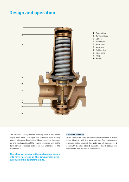




The JRGURED 1140 pressure reducing valve is a balanced single seat valve. The upstream pressure acts equally against valve cone 8 and piston 10 and therefore, the opening and closing action of the valve is controlled only by the down-stream pressure acting on the underside of the membrane 4.
このカタログについて
| ドキュメント名 | JRGURED 1140 - Pressure reducing valves |
|---|---|
| ドキュメント種別 | 製品カタログ |
| ファイルサイズ | 1.2Mb |
| 取り扱い企業 | ジョージフィッシャー株式会社 (この企業の取り扱いカタログ一覧) |
この企業の関連カタログ




このカタログの内容
Page1
JRG Valves
JRGURED 1140
Pressure reducing valves
Page2
Design and operation
1
1 Cover of top
2 2 Turning nipple
3 Spring
4 Membrane
3 5 Valve stem
6 Valve seat
7 Rubber disc
8 Valve cone
9 Plug
10 Piston
4
10
5
6
7
8
9
The JRGURED 1140 pressure reducing valve is a balanced Cero-flow condition
single seat valve. The upstream pressure acts equally When there is no flow, the downstream pressure is abso-
against valve cone 8 and piston 10 and therefore, the open- lutely identical with the valve setting. The downstream
ing and closing action of the valve is controlled only by the pressure acting against the underside of membrane 4
down-stream pressure acting on the underside of the pulls with the valve stem 5 the rubber disc 7 against the
membrane 4. valve seat 6 and the flow is interrupted.
Therefore variations in the upstream pressure
will have no effect on the downstream pres-
sure within the operating limits.
Page3
Flow condition Turning nipple 2 counter-clockwise will lower the down-
When a valve on the downstream side of the reducing valve stream pressure, whereas turning clockwise will increase
is opened the reduced pressure will fall below the setpoint. the downstream pressure. The new downstream pressure
This means that the pressure under the membrane 4 is re- can be checked at cero-flow with a pressure gauge.
duced, and the spring 3 will tend to open the valvei.e. be-
tween the valve seat 6 and the rubber disc 7. This allows an Special model
increased flow, which will restore the optimal downstream Please ask for special models not according the standard
pressure. models, an offer.
Operating instructions
Important: A strainer has to be installed in
front of the pressure reducing valve.
(Suitable strainer JRG 1850)
Installation
The JRGURED pressure reducing valve will operate in any
position.
Before installation: Rinse pipes thoroughly
After installation: Rinse entire water system at
maximum capacity in order
to remove all air.
Maintenance
Under normal operating conditions JRGURED pressure re-
ducers do not require any special maintenance. However,
the separately installed strainer has to be cleaned from
time to time according to the amount of dirt in the water.
After removing plug 9 and disc holder 8 the rubber disc 7
can be replaced.
Maximum temperatures
For water up to 70°C (158°F)
For air up to 50°C (122°F)
Standard pressure setting 400 kPa (4 bar)
On request the manufacturer can easily supply valves with
other pressure settings. With the standard spring from
150 kPa (1.5 bar) to 600 kPa (6 bar) and with the special
spring from 650 kPa (6.5 bar) to 1’000 kPa (10 bar). The
downstream pressure set at the factory is indicated on the
cover 1.
Modification of the downstream pressure
Relieve pressure on both sides of the valve. After removing
the cover 1 at the top of the valve the pressure can be ad-
justed with a 36 mm box spanner within the limits as shown
on the graph for the downstream pressure area.
Page4
Sizing the valve
Q Flow quantity
In domestic water installations with high living comfort, Example 1
velocity in the pipes should be between 1 and 2 m/s (3,3 and Which JRGURED pressure reducing valve should be
6,6 ft/s). Using the adjacent graph, the valve size, the ve- chosen for a water flow of 240 l/min.
locity and flow quantity can be determined.
Solution 1
Starting at the figure 240 on the quantity scale and
moving up vertically to the shaded area between velocities
of 1 and 2 m/s the DN 65 (2½”) – line will be intersected.
From this intersection point the respective velocity of 1.2
m /s (4ft/s) will be found when moving horizontally to the
velocity scale.
Example 2
What is flow quantity in l/min through a JRGURED
pressure reducing valve DN 80 (3”) at a velocity of 2 m/s
(6,6 ft/s)?
Solution 2
Starting at the figure 2 m/s on the velocity scale move
horizontally to the right until the DN 80 (3”) – line is
intersected. Now move down to the quantity scale and
read that the flow under this condition is 600 l/min.
Flow velocity v [m/s]
Page5
Determination of pressure drop
m3/h 2 3 4 5 6 8 10 20 30 40 50 60 80 100 120 150
1.5
65 80 100
1 100
0.9 90
0.8 80
0.7 70
0.6 60
0.5 50
0.4 40
0.3 30
0.2 20
0.1 10
l/min 30 40 50 60 80 100 200 300 400 500 600 800 1000 2000 2500
l/s 0.5 1 2 3 4 5 10 15 20 30 40
Q Flow quantity PressuDrreu sckeetitnisntgel l6u0n0g /64000/4 0k0P kaP (a6 (/64/4 b bar)
After sizing the valve as described above using chart 1 it is Example
possible to determine the pressure drop on the adjacent What is the pressure drop through a DN 80 (3”) JRGURED
chart. pressure reducing valve at a flow of 550 l/min.
Solution
Starting at the figure of 550 l/min on the quantity scale,
moving up until the intersection with the line for the DN
80 (3”) valve.Moving horizontally to the right or left to the
pressure drop scale it is seen that the pressure drop for a
flow of 550 litre/min through DN 80 valve is 0.5 bar.
Pressure drop Δp [bar]
Pressure drop Δp [kPa]
Page6
Pressure reducing valve and return flow inhibitor
JRGURED pressure reducing valve, PN 16
made of gunmetal, with flanges according SN EN 1092-2
drilled, seat made of stainless steel, on both site with
manometer connections. Delivery without gaskets.
Manometer and manometer valves see page 7.
JRG Code GF Code DN d1 d2 d3 h1 h2 l1 l2 kg
1140.065 350542301 65 65 187 Rp ¼ 128 340 290 145 4 28.000
1140.080 350542401 80 80 217 Rp ¼ 144 405 310 155 8 43.000
1140.100 350542501 100 100 257 Rp ¼ 166 465 350 175 8 66.000
l1
Adaptor piece for 1430/1440 to 1140
made of gunmetal, incl. special screws and flat gaskets.
d1 d2
s
JRG Code GF Code DN d1 d2 l1 kg
1146.065 355635903 65 65 127 92 4 4.100
1146.080 355635904 80 80 142 102 8 6.200
Page7
Pressure reducing valve and return flow inhibitor
° d 2 Return flow inhibitor, PN 16d 3 with flanges, threaded connection for test and drain valve,
h closed with closure plug 5149, without test and drain
valve, made of bronze, backing flange made of PP with
d1 d4 d5 steel ring, with profile flange gaskets made of EPDM*,
d 3 stainless steel valve seat and closing spring, plastic
return flow inhibitor, PPSU baffle, EPDM seals, for water
l 2 l 3 up to 90°C, opening pressure less than 50 mbar, tested
l 1 according DIN EN 13959, noise tested, valve sound
group 1.
* EPDM gaskets must not be oiled or greased.
JRG Code GF Code DN d1 d2 d3 d4 d5 h l1 l2 l3 kg
1614.040 350898304 40 Rp 1/4 G 1 1/2 Rp 1/4 110 150 90.5 229 94 135 6 4.239
1614.050 350898305 50 Rp 1/4 G 2 Rp 1/4 125 165 107 262 104 158 6 6.660
1614.065 350898306 65 Rp 1 G 2 1/2 Rp 1/4 145 185 116 296 109.5 186.5 6 9.460
Slanted filter, PN 16
made of gunmetal, with flanges, with profile flange
gaskets made of EPDM*, backing flange made of PP with
steel ring, large surface strainer, made of stainless steel
mesh, for water, air, etc. up to 100°C.
* EPDM gaskets must not be oiled or greased.
JRG Code GF Code DN/d1 d2 d3 d4 h l1 l2 l3 µm kg
1814.040 350871340 40 G 1 1/2 110 150 89 229 94 135 250 4x ∅18 4.170
1814.050 350871350 50 G 2 125 165 110.5 262 104 158 250 4x ∅18 6.580
1814.065 350871365 65 G 2 1/2 145 185 122 296 109.5 186.5 560 4x ∅18 9.460
1814.080 350871380 80 G 3 160 200 136 333 121.5 211.5 560 4x ∅18 12.690
Page8
Check-valve 1650
Check-valve, PN 16
made of grey cast iron, plastic coated, with flanges drilled
in accordance with SN EN 1092-2, cone made from
gunmetal, lip gasket made of NBR, test and drain plugs.
For water up to 90°C, for compressed air and other media
up to 70°C.
JRG Code GF Code DN d1 d2 l1 kg
1650.040 355635557 40 150 G 1/4 180 4 9.000
1650.050 355635558 50 165 G 1/4 200 4 11.000
1650.065 355635559 65 185 G 1/2 240 4 16.500
1650.080 355635560 80 200 G 1/2 260 8 20.500
1650.100 355635561 100 230 G 1/2 300 8 28.500
1650.125 355635562 125 250 G 3/4 350 8 41.000
1650.150 355635563 150 285 G 3/4 400 8 60.000
100
80
60
50
40
30
20
10
8
6
5
4
3
2
1
Volume flow V
Pressure drop Dp (bar)
Pressure drop Dp (kPa)
Page9
Slanted filter 1850
Slanted filter, PN 16
made of grey cast iron, plastic coated on the outside and
inside, flanges drilled in accordance with SN EN 1092-2,
filter sieve made of rust-free steel 500 μm, to 90°C.
Minimum distance for the dismantling of the fine filter:
2 x h1.
JRG Code GF Code DN d1 d2 h1 l µm kg
1850.065 355635558 65 65 185 179 290 4 500 15.000
1850.080 355635565 80 80 200 203 310 8 500 22.000
1850.100 355635566 100 100 220 220 350 8 500 30.000
100
80
60
50
40
30
20
10
8
6
5
4
3
2
. 1
Volume flow V
Pressure drop Dp (bar)
Druckverlust Dp (kPa)
Page10
Overview manometer valves
d
2 Manometer valve, PN 1600 kPa (16 bar)
made of brass, with push button, for water and air up to
100°C, suitable to 1140-1142 DN 65/80/100.
d
1
l
JRG Code GF Code DN GN d1 d2 l kg
8103.010 350260504 8 1/4 R 1/4 Rp ¼ 60 0.170
Manometer
d for water and air up to 60°C.
h
h
1
d
1
JRG Code GF Code GN d d1 h h1 bar kg
8107.080 350678901 ¼ 40 R ¼ 38 12 0-12 0.075
8107.081 350110601 ¼ 50 R ¼ 44 12 0-12 0.120
8107.082 350110602 ¼ 50 R ¼ 44 12 0-25 0.120
8107.083 350544702 ¼ 63 R ¼ 52 12 0-12 0.155
8107.084 350544701 ¼ 63 R ¼ 52 12 0-25 0.155
Type JRG Code Dimension Pressure Manometer valve Manometer
DN 65 1
1140 DN 80 0-12 bar0-25 bar2 8103.01
0 8107.083
DN 100 8107.084
1 Secondary pressure
2 Primary pressure
Page12
GF Piping Systems
Worldwide at home
Our sales companies and representatives
ensure local customer support in over 100 countries.
www.gfps.com
Argentina / Southern South America France Middle East Spain / Portugal
Georg Fischer Central Plastics Georg Fischer SAS Georg Fischer Georg Fischer S.A.
Sudamérica S.R.L. 95932 Roissy Charles de Gaulle Cedex Piping Systems (Switzerland) Ltd 28046 Madrid
Buenos Aires, Argentina Phone +33 (0)1 41 84 68 84 Dubai, United Arab Emirates Phone +34 (0) 91 781 98 90
Phone +5411 4512 02 90 Fax. +33 (0)1 41 84 68 85 Phone +971 4 289 49 60 Fax +34 (0) 91 426 08 23
Fax +5411 4512 02 93 fr.ps@georgfischer.com Fax +971 4 289 49 57 es.ps@georgfischer.com
gfcentral.ps.ar@georgfischer.com www.gfps.com/fr gss.ps@georgfischer.com www.gfps.com/es
www.gfps.com/ar www.gfps.com/int
Germany Sweden
Australia Georg Fischer GmbH Netherlands Georg Fischer AB
George Fischer Pty Ltd 73095 Albershausen Georg Fischer N.V. 11743 Stockholm
Riverwood NSW 2210 Phone +49 (0)7161 302 0 8161 PA Epe Phone +46 (0) 8 506 77 50 0
Phone +61 (0)2 9502 8000 Fax +49 (0)7161 302 25 9 Phone +31 (0) 578 678 222 Fax +46 (0) 8 749 23 70
Fax +61 (0)2 9502 8090 info.de.ps@georgfischer.com Fax +31 (0) 578 621 768 info.se.ps@georgfischer.com
australia.ps@georgfischer.com www.gfps.com/de nl.ps@georgfischer.com www.gfps.com/se
www.gfps.com/au www.gfps.com/nl
India Switzerland
Austria Georg Fischer Piping Systems Pvt. Ltd. New Zealand Georg Fischer
Georg Fischer Rohrleitungssysteme GmbH 400 076 Powai, Mumbai Georg Fischer Ltd Rohrleitungssysteme (Schweiz) AG
3130 Herzogenburg Phone +91 22 4007 2001 5140 Upper Hutt 8201 Schaffhausen
Phone +43 (0) 2782 856 43 0 Fax +91 22 4007 2020 Phone +64 (0) 4 527 9813 Phone +41 (0)52 631 30 26
Fax +43 (0) 2782 856 64 branchoffice@georgfischer.com Fax +64 (0) 4 527 9834 Fax +41 (0)52 631 28 00
austria.ps@georgfischer.com www.gfps.com/in nz.ps@georgfischer.com ch.ps@georgfischer.com
www.gfps.com/at www.gfps.com/nz www.gfps.com/ch
Indonesia
Belgium / Luxembourg George Fischer Representative Office Norway Taiwan
Georg Fischer NV/SA 10310 Jakarta Georg Fischer AS Georg Fischer Co. Ltd.
1070 Bruxelles/Brüssel, Belgium Phone +62 21 391 48 62 1351 Rud 24158 New Taipei City
Phone +32 (0)2 556 40 20 Fax +62 21 391 48 63 Phone +47 67 18 29 00 Phone +886 2 8512 2822
Fax +32 (0)2 524 34 26 sgp.ps@georgfischer.com Fax +47 67 13 92 92 Fax +886 2 8512 2823
be.ps@georgfischer.com www.gfps.com/sg no.ps@georgfischer.com tw@georgfischer.com
www.gfps.com/be www.gfps.com/no www.gfps.com/tw
Italy
Brazil Georg Fischer S.p.A. Philippines Turkey
Georg Fischer Sist. de Tub. Ltda. 20063 Cernusco S/N (MI) George Fischer Representative Office Georg Fischer Hakan Plastik
04571-020 São Paulo/SP Phone +39 02 921 86 1 1604 Pasig City Boru ve Profil San. Tic. A.S.
Phone +55 (0)11 5525 1311 Fax +39 02 921 86 24 7 Phone +632 571 2365 59500 Cerkezkoy / Tekirdag
br.ps@georgfischer.com it.ps@georgfischer.com Fax +632 571 2368 Phone +90 282 726 64 43
www.gfps.com/br www.gfps.com/it sgp.ps@georgfischer.com Fax +90 282 726 94 67
www.gfps.com/sg hpsales@hakan.com.tr
Canada Japan www.hakan.com.tr
Georg Fischer Piping Systems Ltd Georg Fischer Ltd Poland
Mississauga, ON L5T 2B2 556-0011 Osaka Georg Fischer Sp. z o.o. United Kingdom / Ireland
Phone +1 (905) 670 8005 Phone +81 (0)6 6635 2691 05 090 Sekocin Nowy George Fischer Sales Ltd
Fax +1 (905) 670 8513 Fax +81 (0)6 6635 2696 Phone +48 (0)22 3131 050 CV2 2ST Coventry, United Kingdom
ca.ps@georgfischer.com jp.ps@georgfischer.com Fax +48 (0)22 3131 060 Phone +44 (0) 2476 535 535
www.gfps.com/ca www.gfps.com/jp poland.ps@georgfischer.com Fax +44 (0) 2476 530 450
www.gfps.com/pl uk.ps@georgfischer.com
China Korea www.gfps.com/uk
Georg Fischer P iping Systems Ltd Georg Fischer Piping Systems Romania
201319 Shanghai 463-824 Seoul Georg Fischer Rohrleitungssysteme (Elvetia) USA /Caribbean
Phone +86 21 3899 3899 Phone +82 31 8017 1450 3 S.A. SUCURSALA BUCURESTI Georg Fischer LLC
Fax +86 21 3899 3888 Fax +82 31 8017 1454 020257 Bucuresti 92618 Irvine
china.ps@georgfischer.com kor.ps@georgfischer.com Phone +40 311 040 492 Phone +1 714 731 88 00
www.gfps.com/cn www.gfps.com/kr Fax +40 212 317 479 Fax +1 714 731 62 01
ro.ps@georgfischer.com Toll Free 800/854 40 90
Denmark / Iceland Malaysia www.gfps.com/int us.ps@georgfischer.com
Georg Fischer A/S George Fischer (M) Sdn. Bhd. Sales Office www.gfpiping.com
2630 Taastrup, Denmark 40460 Shah Alam, Selangor Darul Ehsan Russia
Phone +45 (0) 7022 1975 Phone +60 (0)3 5122 5585 Georg Fischer International
Fax +45 (0) 7022 1976 Fax +60 (0)3 5122 5575 Piping Systems (Switzerland) Ltd Georg Fischer
info.dk.ps@georgfischer.com my.ps@georgfischer.com Moscow Representative Office Piping Systems (Switzerland) Ltd
www.gfps.com/dk www.gfps.com/my 125040 Moscow 8201 Schaffhausen/Switzerland
Phone +7 495 748 11 44 Phone +41 (0) 52 631 30 03
Finland Mexico / Northern Latin America ru.ps@georgfischer.com Fax +41 (0) 52 631 28 93
Georg Fischer AB Georg Fischer S.A. de C.V. www.gfps.com/ru info.export@georgfischer.com
01510 Vantaa Apodaca, Nuevo Leon, Mexico www.gfps.com/int
Phone +358 (0)9 586 58 25 Phone +52 (81) 1340 8586 Singapore
Fax +358 (0)9 586 58 29 Fax +52 (81) 1522 8906 George Fischer Pte Ltd
info.fi.ps@georgfischer.com mx.ps@georgfischer.com 528 872 Singapore
www.gfps.com/fi www.gfps.com/mx Phone +65 6747 0611
Fax +65 6747 05 77
sgp.ps@georgfischer.com
www.gfps.com/sg
The technical data are not binding. They neither constitute expressly 37 221 62
warranted characteristics nor guaranteed properties nor a guaranteed durability. e / 07.18 /
They are subject to modification. Our General Terms of Sale apply.
© Georg Fischer JRG AG
Hauptstrasse 130
CH-4450 Sissach/Switzerland
Telefon +41 (0) 61 975 22 22
info.jrg.ps@georgfischer.com
Printed in Switzerland