


The JRGUMAT thermostatic mixing valve is a three-way valve made of gunmetal, which proportionally regulates the mixed water temperature without the need for auxiliary energy.
このカタログについて
| ドキュメント名 | JRGUMAT - Thermostatic Mixing Valve |
|---|---|
| ドキュメント種別 | 製品カタログ |
| ファイルサイズ | 2Mb |
| 取り扱い企業 | ジョージフィッシャー株式会社 (この企業の取り扱いカタログ一覧) |
この企業の関連カタログ


このカタログの内容
Page1
JRG Valves
JRGUMAT
Thermostatic Mixing Valve
Page2
Operation/Function
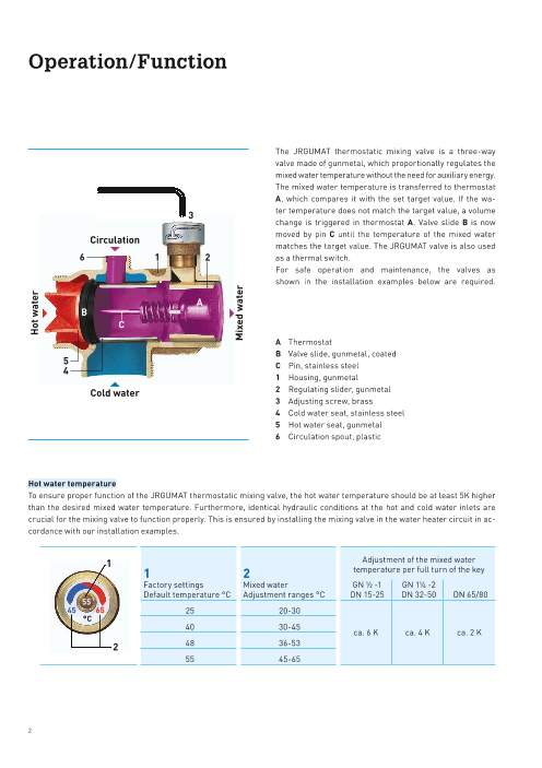
The JRGUMAT thermostatic mixing valve is a three-way
valve made of gunmetal, which proportionally regulates the
mixed water temperature without the need for auxiliary energy.
The mixed water temperature is transferred to thermostat
A, which compares it with the set target value. If the wa-
ter temperature does not match the target value, a volume
change is triggered in thermostat A. Valve slide B is now
moved by pin C until the temperature of the mixed water
Circulation
matches the target value. The JRGUMAT valve is also used
as a thermal switch.
For safe operation and maintenance, the valves as
shown in the installation examples below are required.
A Thermostat
B Valve slide, gunmetal, coated
C Pin, stainless steel
1 Housing, gunmetal
Cold water 2 Regulating slider, gunmetal
3 Adjusting screw, brass
4 Cold water seat, stainless steel
5 Hot water seat, gunmetal
6 Circulation spout, plastic
Hot water temperature
To ensure proper function of the JRGUMAT thermostatic mixing valve, the hot water temperature should be at least 5K higher
than the desired mixed water temperature. Furthermore, identical hydraulic conditions at the hot and cold water inlets are
crucial for the mixing valve to function properly. This is ensured by installing the mixing valve in the water heater circuit in ac-
cordance with our installation examples.
Adjustment of the mixed water
1
1 2 temperature per full turn of the key
Factory settings Mixed water GN ½ -1 GN 1¼ -2
Default temperature °C Adjustment ranges °C DN 15-25 DN 32-50 DN 65/80
55
45 65 25 20-30
°C
40 30-45
ca. 6 K ca. 4 K ca. 2 K
48 36-53
2
55 45-65
2
Hot water
Mixed water
Page3
Nomogram
[ ]
[ ]
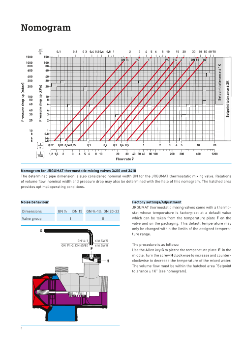
Flow rate V
Nomogram for JRGUMAT thermostatic mixing valves 3400 and 3410
The determined pipe dimension is also considered nominal width DN for the JRGUMAT thermostatic mixing valve. Relations
of volume flow, nominal width and pressure drop may also be determined with the help of this nomogram. The hatched area
provides optimal operating conditions.
Noise behaviour Factory settings/Adjustment
JRGUMAT thermostatic mixing valves come with a thermo-
Dimensions GN ½ DN 15 GN ¾-1¼ DN 20-32 stat whose temperature is factory-set at a default value
Valve group I II which can be taken from the temperature plate F on the
valve and on the packaging. This default temperature may
only be changed within the limits of the assigned tempera-
G
ture range.
GN ½-1 6 kt SW 5
GN 1¼-2, DN 65/80 6 kt SW 8 The procedure is as follows:
F Use the Allen key G to pierce the temperature plate F in the
middle. Turn the screw H clockwise to increase and counter-
H clockwise to decrease the temperature of the mixed water.
The volume flow must be within the hatched area “Setpoint
tolerance ± 1K” (see nomogram).
4
3
Pressure drop Dp [mbar]
Pressure drop Dp [kPa]
Setpoint tolerance ± 1K
Setpoint tolerance ± 2K
Page4
Fields of Application Advantages of
JRGUMAT Thermo-
static Mixing Valves
The well-proven JRGUMAT thermostatic mixing valves are • Delivers mixed water
thermostatically controlled mixing valves which are used
whenever a constant mixed water temperature and high at constant temperature
control accuracy are desired or required, e.g. as central
mixing valve in detached houses and multi-family homes,
hospitals, nursing homes, hotels, barracks, shower rooms • High control accuracy
of sports facilities, industrial and commercial buildings.
• Operates without external power supply
JRGUMAT thermostatic mixing valves also serve as excess
temperature protection in systems using alternative forms
of energy such as solar systems, firewood heating, wood • Protects from scalding
chip furnaces, pellet heating, etc. Thanks to their high con-
trol accuracy, JRGUMAT thermostatic mixing valves can also
be used for special applications, e.g. as controller for high- • Saves energy
temperature maintenance.
• Increases comfort and safety in
the hot water system
Technical changes are reserved.
4
Page5
Installation Instructions/Maintenance/
Transport Packaging
Installation instructions Transport packaging
Follow the installation examples and observe local stan- After installing and adjusting the valve, the transport pack-
dards and guidelines when installing your JRGUMAT valve. aging of the JRGUMAT thermostatic mixing valve is used as
The JRGUMAT thermostatic mixing valve can be mounted in thermal insulation.
any position. – Thermal conductivity lD = 0.033 W/mK
Install only valves (Y-valves, back flow preventers, etc.) with – Fire behaviour (BKZ) 5.1/B1
low pressure drop. Thoroughly flush the supply line before – Application temperature ≤ 90°C
installing the JRGUMAT thermostatic mixing valve.
To prevent the mixing valve from malfunctioning, install it
side by side with the heater and provide it with a 15 cm high
thermosiphon. The unions listed on page 11 are obligatory.
Do not use unions sealing in the thread (e.g. hemp).
AFM 34 gaskets must not be oiled or greased.
Back flow prevention
Install only low pressure drop check valves 1610 to 1615 and
1650, swing check valve 1682 and lockable back flow pre-
venters 5262 to 5284.
Overview of circulation valves used in building services
Soldered union
Static Dynamic
During soldering, the solder-joint unions must be separated Circulation Valves Circulation Valves
from the mixing valve, as the thermostat and the gaskets
may otherwise be damaged.
Maintenance 6310 6320 JRGUTHERM
– JRGUMAT thermostatic mixing valves are virtually Regulation socket Thermostatic circulation valves
maintenance-free.
– The installation and operating instructions are to be
handed over to the building owner on delivery.
6325 JRGUTHERM 2T
– In case of trouble please check your installation with the 6335 Double thermostatic circulation valve for
help of the installation diagrams in this brochure. Needle valve regulated normal and disinfection operation
– Replace the mixing valve in case of malfunctions due to
clogging or calcification of the valve.
3600/3602/3606 JRG LegioTherm 2T
Thermoelectric circulation valve for
a recorded thermal disinfection with
Controller and Master 2/3
3600.115/.120/.415/.420 JRG LegioTherm 2T
Thermoelectric circulation valves for
integration into building management
system
5
Page6
Installation Examples with
JRGUMAT Thermostatic Mixing Valves
Legend
Item No. Text EN 806-1 SIA
– PWC potable water, cold
– PWH potable water, hot
– PWH-C, potable water, hot, circulation
– PWH-M potable water, hot, mixed water
3400/3410 JRGUMAT thermostatic mixing valve
5200–5234 Shut-off valve
1610–1615 Bock flow preventer (controllable)
5262–5284 Shut-off valve with integrated back flow preventer (controllable)
1025/1028 Spring loaded safety valve
6310–6325 Circulation valve
– Liquid pump with mechanical drive
6000–6012 Ball valve
1810–1870 Mechanical filter
– Driven by electric motor M
6410 Driven by electric solenoid
– Timer
– Regulated speed
Notes
1–8 The installation examples are recommendations; we do not assume any responsibility for their completeness.
Adhere to local standards and guidelines when installing safety devices, equipment and valves. These installation
examples serve as guidelines only and should not be relied upon as a substitute for professional advice.
2-5+7 Flow path A = to avoid overheating, regulation socket 6310
Flow path B = to cover the heat loss, JRGUTHERM 6320
5 Thermal and proportional distribution of the flow rates. Control of the flow rates for the flow paths
A and B with JRGUMAT. Size of the circulation valve as a function of circulation losses.
6+7 To ensure thermal disinfection, each tapping point must be flushed.
For thermal disinfection sufficient hot water must be available.
Please note: Scalding hazard during thermal disinfection. Thermal disinfection is possible only with a
JRGUTHERM 2T circulation valve.
1 Observe legend/notes!
Mixed water installation
Option: Hot water outlet
6
Page7
Installation Examples with
JRGUMAT Thermostatic Mixing Valves
2 Observe legend/notes!
Mixed water installation with circulation
Option: Hot water outlet
3 Observe legend/notes!
Mixed water installation with circulation
(Flow path A via cold water inlet of the mixing valve)
Option: Hot water outlet
4 Observe legend/notes!
Mixed water installation with two circuits
Option: Hot water outlet with circulation
7
Page8
Installation Examples with
JRGUMAT Thermostatic Mixing Valves
5 Observe legend/notes!
Mixed water installation with circulation pipe ≥ ¾“
1 = Cold water inlet
2 = Hot water inlet
3 = Mixed water outlet
6 Observe legend/notes!
Mixed water installation with thermal disinfection
Option: Hot water outlet
7 Observe legend/notes!
Mixed water installation with circulation and thermal disinfection
Option: Hot water outlet
8
Page9
Installation Examples with
JRGUMAT Thermostatic Mixing Valves
8 Observe legend/notes!
Regulating the storage capacity with JRGUMAT
1 = Cold water inlet
2 = Hot water inlet
3 = Mixed water outlet
4 = Circulation input with cap 8325
9 Observe legend/notes!
Fixed setpoint control at constant temperature (heating)
9
Page10
JRGUMAT Thermostatic Mixing Valve 3400
JRGUMAT thermostatic mixing valve, PN 10
Gunmetal housing,
male threaded connections for unions,
standard temperatures 25/40/48/55°C,
Factory settings can be adjusted with Allen key.
Please observe max. permissible water temperature.
Unions and cap 8325 see page 12 onwards.
Use AFM 34 gaskets which must neither be oiled nor
greased.
Item No. GN DN Code d2 d3 h1 h2 h3 l l1 l2 °C max. temp.°C kg
3400.910 ½ 15 350760501 G 11/8 – – 47 35 90 35 55 5 25 90 0.570
3400.912 ½ 15 350760502 G 11/8 – – 47 35 90 35 55 5 40 90 0.570
3400.914 ½ 15 350760507 G 11/8 – – 47 35 90 35 55 5 48 90 0.570
3400.916 ½ 15 350760503 G 11/8 – – 47 35 90 35 55 5 55 90 0.570
3400.920 ¾ 20 350760401 G 1¼ G ½ 32 49 40 100 40 60 5 25 90 0.650
3400.922 ¾ 20 350760402 G 1¼ G ½ 32 49 40 100 40 60 5 40 90 0.650
3400.924 ¾ 20 350760407 G 1¼ G ½ 32 49 40 100 40 60 5 48 90 0.650
3400.926 ¾ 20 350760403 G 1¼ G ½ 32 49 40 100 40 60 5 55 90 0.650
3400.930 1 25 350760301 G 1½ G ¾ 36 51 43 110 43 67 5 25 90 0.870
3400.932 1 25 350760302 G 1½ G ¾ 36 51 43 110 43 67 5 40 90 0.870
3400.934 1 25 350760307 G 1½ G ¾ 36 51 43 110 43 67 5 48 90 0.870
3400.936 1 25 350760303 G 1½ G ¾ 36 51 43 110 43 67 5 55 90 0.870
3400.940 1¼ 32 350760201 G 2 G ¾ 41 75 52 130 52 78 8 25 70 1.600
3400.942 1¼ 32 350760202 G 2 G ¾ 41 75 52 130 52 78 8 40 85 1.600
3400.944 1¼ 32 350760207 G 2 G ¾ 41 75 52 130 52 78 8 48 90 1.600
3400.946 1¼ 32 350760203 G 2 G ¾ 41 75 52 130 52 78 8 55 105 1.600
3400.950 1½ 40 350760101 G 2¼ G ¾ 50 77 58 150 58 92 8 25 70 2.100
3400.952 1½ 40 350760102 G 2¼ G ¾ 50 77 58 150 58 92 8 40 85 2.100
3400.954 1½ 40 350760107 G 2¼ G ¾ 50 77 58 150 58 92 8 48 90 2.100
3400.956 1½ 40 350760103 G 2¼ G ¾ 50 77 58 150 58 92 8 55 105 2.100
3400.960 2 50 350760001 G 2¾ G ¾ 60 85 70 180 70 110 8 25 65 3.370
3400.962 2 50 350760002 G 2¾ G ¾ 60 85 70 180 70 110 8 40 80 3.370
3400.964 2 50 350760007 G 2¾ G ¾ 60 85 70 180 70 110 8 48 85 3.370
3400.966 2 50 350760003 G 2¾ G ¾ 60 85 70 180 70 110 8 55 90 3.370
10
Page11
JRGUMAT Thermostatic Mixing Valve 3410
JRGUMAT thermostatic mixing valve, PN 10
Gunmetal housing,
all connections with flanges according to SN EN 1092 with
three flange gaskets.
Standard temperatures 25/40/48/55°C,
factory settings can be adjusted with Allen key.
Please observe max. permissible water temperature.
Unions and cap 8325 for circulation connection see chart
below.
Item No. DN Code d1 d2 d3 h1 h2 l1 l2 l3 °C max. temp.°C kg
3410.601 65 350767204 65 G 1½ 185 82 121 145 290 112 4 25 65 23.000
3410.605 65 350767205 65 G 1½ 185 82 121 145 290 112 4 40 80 23.000
3410.606 65 350767208 65 G 1½ 185 82 121 145 290 112 4 48 85 23.000
3410.608 65 350767206 65 G 1½ 185 82 121 145 290 112 4 55 90 23.000
3410.801 80 350767404 80 G 2 200 92 127 155 310 124 8 25 65 28.000
3410.805 80 350767405 80 G 2 200 92 127 155 310 124 8 40 80 28.000
3410.806 80 350767408 80 G 2 200 92 127 155 310 124 8 48 85 28.000
3410.808 80 350767406 80 G 2 200 92 127 155 310 124 8 55 90 28.000
Overview unions for JRGUMAT thermostatic mixing valves 3410, 3412
8325 8331 8209 8204 8351 8356 4700 8360
11
Page12
Overview Unions for
JRGUMAT Thermostatic Mixing Valve 3400
Use only the unions listed below. Installation example
AFM 34 gaskets must not be oiled or greased.
3400
8360
* Union 8337 with check valve only for
5281 5211
GN ½ (DN 15), or GN 15 (DN12) and
GN ¾ (DN 20), or GN 22 (DN 20).
8360
** Union 4700 only for max. GN 1¼ (DN 32).
8360
*** Elbow union 8341 and angle valve 8347 5281
only for max. ¾ (DN 20).
12
Page13
Unions for JRGUMAT Thermostatic Mixing
Valves 3400 and 3410
Adapter
Gunmetal housing, with gaskets*, for replacing 3350 with
3400 including cap 8325 for circulation connection.
Two-piece set for GN 1½ and 2.
* AFM 34 gaskets must not be greased or oiled.
Item No. GN DN Code d1 l1 l2 R kg
3480.320 ¾ 20 350597601 G 1¼ 30.5 40.5 47 – 09 294 14 0.490
3480.400 1 25 350597701 G 1½ 38.0 34.0 55 – 09 294 15 0.755
3480.480 1¼ 32 350597801 G 2 39.5 33.5 66 – 09 287 06 1.000
3480.560 1½ 40 350597901 G 2¼ 44.5 30.5 72 2 halves 09 287 23 1.180
3480.640 2 50 350598001 G 2¾ 44.5 34.5 89 2 halves 09 287 84 1.750
Valve adapter
l1
l Gunmetal, with female thread and gasket*, MT plastic crimp l2 3
z flange union for JRG Sanipex d16/d20/d25 and JRG Sanipex MT 1
pipes.
d1 d * AFM 34 gaskets must not be greased or oiled.
Item No. GN-d Code d d1 l1 l2 l3 z1 kg
4700.120 1¼ -16 351616996 16 G 1¼ 41.0 8.0 33.0 14.5 46 09 294 14 0.119
4700.122 1¼ -20 351620994 20 G 1¼ 46.0 8.0 38.0 15.5 46 09 294 14 0.125
4700.124 1¼ -26 351626995 26 G 1¼ 55.5 8.0 47.5 18.5 46 09 294 14 0.150
4700.126 1¼ -32 351632995 32 G 1¼ 65.5 8.0 57.5 19.5 46 09 294 14 0.195
4700.128 1½ -26 351626996 26 G 1½ 56.5 9.0 47.5 18.5 54 09 294 15 0.204
4700.130 1½ -32 351632996 32 G 1½ 66.5 9.0 57.5 19.5 54 09 294 15 0.243
4700.132 1½-40 351640995 40 G 1½ 77.5 9.0 68.5 23.5 55 09 294 15 0.325
4700.136 2-40 351640996 40 G 2 82.5 13.5 69.0 24.5 67 09 294 36 0.410
4700.138 2¼-50 351650996 50 G 2¼ 82.5 11.0 71.5 34.0 72 09 294 41 0.667
4700.142 2¾-63 351663996 63 G 2¾ 100.0 13.5 86.5 40.0 89 09 294 43 1.119
13
Page14
Unions for JRGUMAT Thermostatic Mixing
Valves 3400 and 3410
Threaded union
Brass, with gasket*, for the circulation connection.
* AFM 34 gaskets must not be greased or oiled.
Item No. GN DN Code d1 d2 l1 l2 circulation union kg
8200.160 3/8 10 350278401 R 3/8 G ½ 21.5 5.5 24 GN ¾ 09 294 01 0.050
8201.240 ½ 15 350331701 R ½ G ¾ 25.0 6.0 30 GN 1-2 09 294 23 0.075
Threaded union
Malleable cast iron, galvanized, female thread and gasket*.
* AFM 34 gaskets must not be greased or oiled.
Item No. GN DN Code d1 d2 l1 l2 z circulation union kg
8204.240 ½ 15 350485601 Rp ½ G 11/8 23 9.5 10 44 09 294 24 0.150
8204.320 ¾ 20 350485701 Rp ¾ G 1¼ 24 10.5 9 48 09 294 04 0.170
8204.400 1 25 350485801 Rp 1 G 1½ 27 11.0 10 54 DN 65 09 294 05 0.230
8204.480 1¼ 32 350485901 Rp 1¼ G 2 32 11.5 13 67 DN 80 09 294 09 0.370
8204.560 1½ 40 350486001 Rp 1½ G 2¼ 34 12.5 15 73 09 294 07 0.450
8204.640 2 50 350486101 Rp 2 G 2¾ 36 14.5 12 90 09 294 10 0.690
Soldered union
Brass/gunmetal, with gasket*, for the circulation
connection.
* AFM 34 gaskets must not be greased or oiled.
Item No. GN DN Code d1 d2 l1 l2 z circulation union kg
8205.012 12 10 350196901 12 G ½ 16.5 5.5 5.5 24 GN ¾ 09 294 01 0.050
8205.015 15 12 350262301 15 G ¾ 19.5 6.0 7.5 30 GN 1-2 09 294 23 0.060
8205.018 18 15 350262601 18 G ¾ 21.5 6.0 7.5 30 GN 1-2 09 294 23 0.070
14
Page15
Unions for JRGUMAT Thermostatic Mixing
Valves 3400 and 3410
Soldered union
Brass/gunmetal, with gasket*.
* AFM 34 gaskets must not be greased or oiled.
Item No. GN DN Code d1 d2 l1 l2 z for 3400 circul. union kg
8209.015 15 12 350485102 15 G 11/8 21.0 8.0 7.5 41 GN ½ 09 294 24 0.140
8209.018 18 15 350484102 18 G 11/8 23.0 8.0 7.5 41 GN ½ 09 294 24 0.140
8209.022 22 20 350484201 22 G 1¼ 23.5 8.0 6.5 46 GN ¾ 09 294 04 0.180
8209.028 28 25 350484301 28 G 1½ 26.0 9.0 6.0 54 GN 1 DN 65 09 294 05 0.240
8209.035 35 32 350484401 35 G 2 32.5 9.0 7.5 66 GN 1¼ DN 80 09 294 09 0.430
8209.042 42 40 350484601 42 G 2¼ 36.5 11.0 7.5 72 GN 1½ 09 294 07 0.500
8209.054 54 50 350484801 54 G 2¾ 41.5 13.5 7.5 89 GN 2 09 294 10 0.850
Cap
Brass, with gasket*, for the circulation connection.
* AFM 34 gaskets must not be greased or oiled.
Item No. GN DN Code d1 h circulation union kg
8325.240 ½ 15 350756701 G ½ 9.0 25 GN ¾ 09 406 02 0.030
8325.320 ¾ 20 350756801 G ¾ 9.0 30 GN 1-2 09 406 03 0.040
8325.560 1½ 40 350769801 G 1½ 10.5 55 DN 65 09 406 04 0.180
8325.640 2 50 350769901 G 2 10.5 65 DN 80 09 406 05 0.230
15
Page16
Unions for JRGUMAT Thermostatic Mixing
Valves 3400 and 3410
Union
Gunmetal, with female thread and gasket*.
* AFM 34 gaskets must not be greased or oiled.
Item No. GN DN Code d1 d2 l1 l2 z circulation union kg
8331.240 ½ 15 350217101 Rp ½ G 11/8 8.0 22.5 9.5 41 09 294 24 0.150
8331.320 ¾ 20 350253301 Rp ¾ G 1¼ 8.0 22.5 7.5 46 09 294 04 0.180
8331.400 1 25 350253401 Rp 1 G 1½ 9.0 27.0 10.0 54 DN 65 09 294 05 0.250
8331.480 1¼ 32 350253501 Rp 1¼ G 2 10.0 29.0 10.0 66 DN 80 09 294 09 0.440
8331.560 1½ 40 350253601 Rp 1½ G 2¼ 11.0 33.0 14.0 72 09 294 07 0.570
8331.640 2 50 350253701 Rp 2 G 2¾ 13.5 35.5 11.5 89 09 294 10 0.850
Union with back flow preventer, PN 10
Brass, with female thread, loose nut and back flow pre-
venter, for water up to 90 °C.
Item No. GN DN Code d1 d2 l1 l2 z kg
8337.240 ½ 15 350768601 Rp ½ G 11/8 8 38.5 25.5 41 0.195
8337.320 ¾ 20 350768801 Rp ¾ G 1¼ 8 44.5 29.5 46 0.265
Union, lockable, PN 10
2 3 1
Gunmetal, with gasket*, with female thread, lockable with
ball valve, EPDM O-ring, loose brass nut, for water up to
d 90 °C.1 d2
* AFM 34 gaskets must not be greased or oiled.
z
l
Item No. GN DN Code d1 d2 l z 1 2 3 kg
8339.240 ½ 15 350887710 Rp ½ G ¾ 55 39.5 30 27 6 09 294 09 0.170
8339.320 ¾ 20 350887910 Rp ¾ G 1 55 39.5 37 32 6 09 294 21 0.200
16
Page17
Unions for JRGUMAT Thermostatic Mixing
Valves 3400 and 3410
Union for Mapress press fitting system BR 1
With press socket and loose nut, flat sealing gasket*.
* AFM 34 gaskets must not be greased or oiled.
Item No. GN DN Code d1 d2 l1 l2 z circulation union kg
8350.015 15 12 355600201 15 G ¾ 30.5 6.5 11.0 30 1-2 09 294 02 0.078
8350.018 18 15 355600207 18 G ¾ 30.5 6.5 11.5 30 1-2 09 294 02 0.080
Union for Mapress press fitting system BR 2
With press socket and loose nut, flat sealing gasket*.
* AFM 34 gaskets must not be greased or oiled.
Item No. GN DN Code d1 d2 l1 l2 z circulation union kg
8351.015 15 12 355600401 15 G 11/8 39 8.0 19 41 09 294 24 0.118
8351.018 18 15 355600407 18 G 1¼ 39 8.0 18 46 09 294 04 0.157
8351.022 22 20 355600402 22 G 1¼ 42 8.0 21 46 09 294 04 0.160
8351.028 28 25 355600403 28 G 1½ 44 9.0 21 54 DN 65 09 294 05 0.245
8351.035 35 32 355600404 35 G 2 49 11.0 23 66 DN 80 09 294 09 0.350
8351.042 42 40 355600405 42 G 2¼ 52 11.0 22 72 09 294 07 0.413
8351.054 54 50 355600406 54 G 2¾ 57 13.5 22 89 09 294 10 0.560
Union for Optipress/Viega-Sanpress system BR 1
With press socket and loose nut, flat sealing gasket*.
* AFM 34 gaskets must not be greased or oiled.
Item No. GN DN Code d1 d2 l1 l2 z circulation union kg
8355.015 15 12 355600601 15 G ¾ 37 9 13 31 1-2 09 294 02 0.100
8355.018 18 15 355600602 18 G ¾ 40 9 16 31 1-2 09 294 02 0.100
17
Page18
Unions for JRGUMAT Thermostatic Mixing
Valves 3400 and 3410
Union for Optipress/Viega-Sanpress system BR 2
With press socket and loose nut, flat sealing gasket*.
* AFM 34 gaskets must not be greased or oiled.
Item No. GN DN Code d1 d2 l1 l2 z circulation union kg
8356.015 15 12 355600801 15 G 11/8 39 10 15 42 09 294 24 0.140
8356.018 18 15 355600808 18 G 1¼ 40 9 18 46 09 294 04 0.180
8356.022 22 20 355600802 22 G 1¼ 36 11 12 50 09 294 04 0.195
8356.028 28 25 355600803 28 G 1½ 38 12 14 52 DN 65 09 294 05 0.190
8356.035 35 32 355600804 35 G 2 39 12 15 64 DN 80 09 294 09 0.275
8356.042 42 40 355600805 42 G 2¼ 48 12 12 73 09 294 07 0.565
8356.054 54 50 355600806 54 G 2¾ 55 17 15 88 09 294 10 0.635
Sleeve union, BR 2 on BR 1
For combinations, for valves with male thread according to
EN ISO 228-1, made of gunmetal, with female thread, loose
nut and gaskets*.
* AFM 34 gaskets must not be greased or oiled.
Item No. GN Code d1 d2 l l1 l2 l3 z 1 2 kg
8360.015 15 351061403 G ¾ G 11/8 56.0 6 8.0 22 42 22 41 09 294 23/09 294 24 0.220
8360.020 20 351061413 G 1 G 1¼ 57.0 7 8.0 22 42 27 46 09 294 21/09 294 04 0.298
8360.025 25 351061423 G 1¼ G 1½ 61.0 8 9.0 22 44 32 54 09 294 04/09 294 05 0.452
8360.032 32 351061433 G 1½ G 2 65.0 9 9.0 22 47 41 66 09 294 05/09 294 09 0.669
8360.040 40 351061443 G 1¾ G 2¼ 68.0 10 11.0 22 48 48 72 09 294 06/09 294 07 0.738
8360.050 50 351061453 G 23/8 G 2¾ 73.5 11 13.5 22 49 58 89 09 294 12/09 294 10 1.164
18
Page19
Accessories for JRGUMAT
Elbow union, PN 10
Gunmetal, with gasket*, male threaded inlet, outlet with
loose nut, rosette and threaded connection for thermom-
eter, for mixed water outlet, JRGUMAT 3400.
* AFM 34 gaskets must not be greased or oiled.
Item No. GN DN Code d1 d2 d3 h2 h3 l1 l2 l3 version kg
8341.240 ½ 15 350759902 R ½ G 11/8 65 35 32 40 8 25 32 raw 09 294 24 0.400
8341.320 ¾ 20 350756402 R ¾ G 1¼ 65 45 34 46 8 25 39 raw 09 294 04 0.600
Angle shut-off valve, PN 10
Gunmetal, with gasket*, male threaded inlet, plastic check
valve, outlet with loose nut and rosette, for cold and hot wa-
ter inlet up to 90 °C for JRGUMAT 3400.
* AFM 34 gaskets must not be greased or oiled.
Item No. GN DN Code d1 d2 d3 h2 h3 l1 l2 l3 version kg
8347.240 ½ 15 350759901 R ½ G 11/8 65 35 48 40 8 25 32 raw 09 294 24 0.480
8347.320 ¾ 20 350756401 R ¾ G 1¼ 65 45 52 46 8 25 39 raw 09 294 04 0.750
Thermometer
Plastic and brass, suitable for thermowell 8348.080.
Accuracy class 2.
Item No. Code d d1 l1 kg
8348.001 350830194 52 9 61.5 0.027
d 1
Thermowell
d2 Stainless steel, EPDM gasket, suitable for thermometer
8348.001.
l l 1 2
Item No. Code d1 d2 l1 l2 kg
8348.080 350830192 G 1/4 9 15 35 13 0.022
Thermometer
Stainless steel, suitable for JRGUMAT compact water facili-
ty 3500 and 3510, JRGUTHERM 2T 6325 and elbow unit 8341.
Accuracy class 2.
Item No. Code d d1 l1 l2 kg
8349.080 350830191 52 G ¼ 19 35 17 0.071
Page20
Georg Fischer JRG AG
Worldwide at home
Our sales companies and representatives
ensure local customer support in over 100 countries.
www.gfps.com
Argentina / Southern South America Finland Mexico / Northern Latin America Singapore
Georg Fischer Central Plastics Georg Fischer AB Georg Fischer S.A. de C.V. George Fischer Pte Ltd
Sudamérica S.R.L. 01510 VANTAA Apodaca, Nuevo Leon 11 Tampines Street 92, #04-01/07
Buenos Aires, Argentina Phone +358 (0) 9 586 58 25 CP66636 Mexico 528 872 Singapore
Phone +54 11 4512 02 90 Fax +358 (0) 9 586 58 29 Phone +52 (81) 1340 8586 Phone +65 6747 0611
gfcentral.ps.ar@georgfischer.com info.fi.ps@georgfischer.com Fax +52 (81) 1522 8906 sgp.ps@georgfischer.com
www.gfps.com/ar www.gfps.com/fi mx.ps@georgfischer.com www.gfps.com/sg
www.gfps.com/mx
Australia France Spain / Portugal
George Fischer Pty Ltd Georg Fischer SAS Middle East Georg Fischer S.A.
Riverwood NSW 2210 Australia 95932 Roissy Charles de Gaulle Cedex Georg Fischer 28046 Madrid
Phone +61 (0) 2 9502 8000 Phone +33 (0) 1 41 84 68 84 Piping Systems (Switzerland) Ltd Phone +34 (0) 91 781 98 90
australia.ps@georgfischer.com fr.ps@georgfischer.com Dubai, United Arab Emirates es.ps@georgfischer.com
www.gfps.com/au www.gfps.com/fr Phone +971 4 289 49 60 www.gfps.com/es
gss.ps@georgfischer.com
Austria Germany www.gfps.com/int Sweden
Georg Fischer Rohrleitungssysteme GmbH Georg Fischer GmbH Georg Fischer AB
3130 Herzogenburg 73095 Albershausen Netherlands 117 43 Stockholm
Phone +43 (0) 2782 856 43-0 Phone +49 (0) 7161 302-0 Georg Fischer N.V. Phone +46 (0) 8 506 775 00
austria.ps@georgfischer.com info.de.ps@georgfischer.com 8161 PA Epe info.se.ps@georgfischer.com
www.gfps.com/at www.gfps.com/de Phone +31 (0) 578 678 222 www.gfps.com/se
nl.ps@georgfischer.com
Georg Fischer Fittings GmbH India www.gfps.com/nl Switzerland
3160 Traisen Georg Fischer Piping Systems Ltd Georg Fischer
Phone +43 (0) 2762 90300 400 076 Mumbai Georg Fischer Waga N.V. Rohrleitungssysteme (Schweiz) AG
fittings.ps@georgfischer.com Phone +91 224007 2001 NL-8160 AG Epe 8201 Schaffhausen
www.fittings.at branchoffice@georgfischer.com Phone +31 (0) 578 678 378 Phone +41 (0) 52 631 30 26
www.gfps.com/in waga.ps@georgfischer.com ch.ps@georgfischer.com
Belgium / Luxembourg www.waga.nl www.gfps.com/ch
Georg Fischer NV/SA Italy
1070 Bruxelles/Brüssel Georg Fischer S.p.A. New Zealand Taiwan
Phone +32 (0) 2 556 40 20 20063 Cernusco S/N (MI) Georg Fischer Ltd Georg Fischer Co., Ltd
be.ps@georgfischer.com Phone +39 02 921 861 13 Jupiter Grove, Upper Hutt 5018 San Chung Dist., New Taipei City
www.gfps.com/be it.ps@georgfischer.com PO Box 40399, Upper Hutt 5140 Phone +886 2 8512 2822
www.gfps.com/it Phone +64 (0) 4 527 9813 Fax +886 2 8512 2823
Brazil nz.ps@georgfischer.com www.gfps.com/tw
Georg Fischer Sist. de Tub. Ltda. Georg Fischer TPA S.r.l. www.gfps.com/nz
04795-100 São Paulo IT-16012 Busalla (GE) United Kingdom / Ireland
Phone +55 (0) 11 5525 1311 Phone +39 010 962 47 11 Norway George Fischer Sales Limited
br.ps@georgfischer.com tpa.ps@georgfischer.com Georg Fischer AS Coventry, CV2 2ST
www.gfps.com/br www.gfps.com/it 1351 Rud Phone +44 (0) 2476 535 535
Phone +47 67 18 29 00 uk.ps@georgfischer.com
Canada Japan no.ps@georgfischer.com www.gfps.com/uk
Georg Fischer Piping Systems Ltd Georg Fischer Ltd www.gfps.com/no
Mississauga, ON L5T 2B2 556-0011 Osaka, USA /Caribbean
Phone +1 (905) 670 8005 Phone +81 (0) 6 6635 2691 Poland Georg Fischer LLC
Fax +1 (905) 670 8513 jp.ps@georgfischer.com Georg Fischer Sp. z o.o. Tustin, CA 92780-7258
ca.ps@georgfischer.com www.gfps.com/jp 05-090 Sekocin Nowy Phone +1 (714) 731 88 00
www.gfps.com/ca Phone +48 (0) 22 31 31 0 50 Toll Free 800/854 40 90
Korea poland.ps@georgfischer.com us.ps@georgfischer.com
China Georg Fischer Piping Systems www.gfps.com/pl www.gfpiping.com
Georg Fischer Piping Systems Ltd 271-3 Seohyeon-dong Bundang-gu
Shanghai 201319 Seongnam-si, Gyeonggi-do Romania Georg Fischer Central Plastics LLC
Phone +86 21 3899 3899 Seoul 463-824 Georg Fischer Shawnee, OK 74801
china.ps@georgfischer.com Phone +82 31 8017 1450 Piping Systems (Switzerland) Ltd Phone +1 (405) 273 63 02
www.gfps.com/cn Fax +82 31 8017 1454 020257 Bucharest - Sector 2 gfcentral.ps@georgfischer.com
kor.ps@georgfischer.com Phone +40 (0) 21 230 53 80 www.centralplastics.com
Chinaust Plastics Corp. Ltd. www.gfps.com/kr ro.ps@georgfischer.com
Songlindian, Zhuozhou city, www.gfps.com/int Vietnam
Hebei province, China, 072761 Malaysia George Fischer Pte Ltd
Phone +86 312 395 2000 George Fischer (M) Sdn. Bhd. Russia 136E Tran Vu, Ba Dinh District, Hanoi
Fax +86 312 365 2222 40460 Shah Alam, Selangor Darul Ehsan Georg Fischer Phone +84 4 3715 3290
chinaust@chinaust.com Phone +60 (0) 3 5122 5585 Piping Systems (Switzerland) Ltd Fax +84 4 3715 3285
www.chinaust.com.cn my.ps@georgfischer.com Moscow 125047
www.gfps.com/my Phone +7 495 258 60 80 International
Denmark / Iceland ru.ps@georgfischer.com Georg Fischer
Georg Fischer A/S www.gfps.com/ru Piping Systems (Switzerland) Ltd
2630 Taastrup 8201 Schaffhausen/Switzerland
Phone +45 (0) 70 22 19 75 Phone +41 (0) 52 631 30 03
info.dk.ps@georgfischer.com Fax +41 (0) 52 631 28 93
www.gfps.com/dk info.export@georgfischer.com
www.gfps.com/int
The technical data are not binding. They neither constitute expressly
warranted characteristics nor guaranteed properties nor a guaranteed durability.
They are subject to modification. Our General Terms of Sale apply.
37 242 62
2 (10.14) SMS
© Georg Fischer JRG AG
Hauptstrasse 130
CH-4450 Sissach/Switzerland
Phone +41 (0) 61 975 22 22
info.jrg.ps@georgfischer.com
Printed in Switzerland