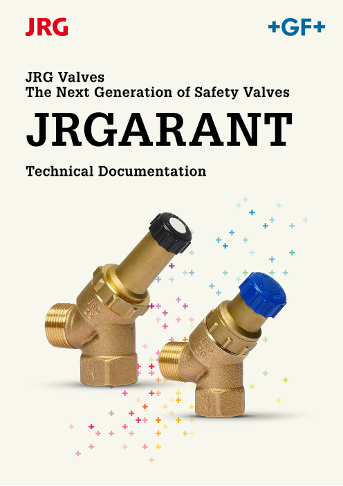




JRGARANT safety valves JRG Code 1025 and 1028 protect water heaters (closed design) from pressure-related overload.
このカタログについて
| ドキュメント名 | JRGARANT - The Next Generation of Safety Valves |
|---|---|
| ドキュメント種別 | 製品カタログ |
| ファイルサイズ | 1.4Mb |
| 取り扱い企業 | ジョージフィッシャー株式会社 (この企業の取り扱いカタログ一覧) |
この企業の関連カタログ



このカタログの内容
Page1
JRG Valves
The Next Generation of Safety Valves
JRGARANT
Technical Documentation
Page2
JRGARANT Safety Valves
Safety guaranteed
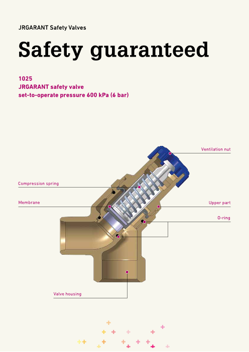
1025
JRGARANT safety valve
set-to-operate pressure 600 kPa (6 bar)
Ventilation nut
Compression spring
Membrane Upper part
O-ring
Valve housing
2
Page3
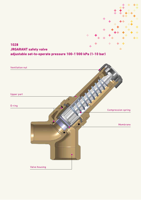
1028
JRGARANT safety valve
adjustable set-to-operate pressure 100-1’000 kPa (1-10 bar)
Ventilation nut
Upper part
O-ring
Compression spring
Membrane
Valve housing
3
Page4
JRGARANT Safety Valves
JRGARANT safety valves JRG Code 1025 and
Water heater
1028 protect water heaters (closed design)
from pressure-related overload. Water Max. Outlet
volume heat GN
safety Outlet
Function output
Litres kW valve pipe
When heating water, its volume expands, which causes
pressure to increase in a closed system. The backflow up to 200 75 ½" ½“
preventer installed in the supply line prevents the water
from flowing back from the water heater into the piping 200–1‘000 150 ¾“ ¾“
system. The safety valve opens as soon as the set-to-operate 1‘000–5‘000 250 1“ 1“
pressure is reached and the water volume that caused the
overpressure is discharged.
Set-to-operate pressure of JRGARANT safety valves Installation
Safety valves JRG Code 1025 are factory-set at 600 kPa (6 bar) The safety valve must be installed vertically and easily
and must not be modified. accessible. No shut-off valve may be installed between
safety valve and water heater.
On request, factory-set pressures of 100 – 1,000 kPa (1 – 10 bar) Surplus water is to be drained using a visible and free outlet
can be supplied under JRG code 1028. Please specify the through the shortest possible pipe into a sufficiently
desired set-to-operate pressure when placing your order. dimensioned drainage pipe (see „nomogram discharge
capacity – vent position“).
Application
JRGARANT safety valves are approved for the following In order to ensure smooth operation, we recommend using
parameters water-drip nozzles JRG Code 8225 and 8228.
Thoroughly rinse the supply pipe before commissioning the
Water temperature: Max. 95 °C safety valve.
Pressure: Max. 1000 kPa (10 bar) During the heating phase of the water heater, water must
leak from the safety valve outlet (expansion).
(Paragraphs 5.3 and 9 of SN EN 1491, as well as paragraph The drainage pipe or the nozzle of the safety valve must not
6.4.2 of W3, SVGW edition 2013) be closed.
4
Page5
JRGARANT Safety Valves
Nomogram discharge capacity – vent position
m3 h
3.60 4.32 5.04 5.76 6.48 7.20 7.92 8.64 9.36 10.08 10.80 11.52 12.24 12.96 13.68
1000 DN 15/20 DN 25 10
900 9
800 8
700 7
600 6
500 5
400 4
300 3
200 2
100 1
60 72 84 96 108 120 132 144 156 168 180 192 204 216 228
L min
1.0 1.2 1.4 1.6 1.8 2.0 2.2 2.4 2.6 2.8 3.0 3.2 3.4 3.6 3.8
L s
Connecting a water heater: Periodic functional checks
By turning the ventilation nut in the direction of the arrow by
one notch, the function of the safety valve is checked. By
3 turning the ventilation nut by another notch, the valve is
reset to operating position.
4 The operator of the system is obliged to carry out above-
2 described functional check every six months. The valve must
1 be rinsed for 5 –10 seconds during this functional check.
JRGARANT safety valves are virtually maintenance-free.
They must not be repaired.
5
6
1 Water heater
2 Shut-off valve
3 Safety valve
4 Backflow preventer
5 Hot water outlet valve
6 Drain valve
5
kPa
ba r
Page6
JRGARANT Safety Valves
Produkcttes
Safety valve JRGARANT, reaction pressure 6 bar
For closed model water heater, inlet with male thread, outlet with female thread. Body made of
gunmetal, upper part made of metal, factory setting of operating pressure for the safety valve.
U pper part to 1025 see 1045, water dropping nipple to 1025 see 8223.
GN DN JRG GF Weight
(inch) (mm) Code Code (kg)
1∕2 15 1025.240 350 599 481 0.325
3∕4 20 1025.320 350 599 581 0.370
1 25 1025.400 350 599 610 0.620
GN DN d1 R d2 Rp h1 h2 l1 l2 PN Temperature z
(inch) (mm) (inch) (inch) (mm) (mm) (mm) (mm) (bar) (°C) (mm)
1∕2 15 1∕ 12 ∕2 28 60 38 47 10 90 15
3∕4 20 3∕ 34 ∕4 32 62 41 48 10 90 17
1 25 1 1 39 65 46 49 10 90 22
Safety valve JRGARANT, reaction pressure available between 1-10 bar
For closed model water heater, inlet with male thread, outlet with female thread. Body made of
gunmetal, upper part made of metal, factory setting of operating pressure for the safety valve.
Upper part to 1028 see 1048, water dropping nipple to 1028 see 8223.
• Please specify the desired initial response pressure when placing your order.
GN DN JRG GF Weight
(inch) (mm) Code Code (kg)
1∕2 15 1028.240 350 599 944 0.400
3∕4 20 1028.320 350 599 945 0.684
1 25 1028.400 350 599 946 0.684
GN DN d1 R d2 Rp h1 h2 l1 l2 PN Temperature z
(inch) (mm) (inch) (inch) (mm) (mm) (mm) (mm) (bar) (°C) (mm)
1∕ 1 12 15 ∕2 ∕2 28 81 38 38 10 90 15
3∕4 20 3∕ 34 ∕4 32 81 41 68 10 90 17
1 25 1 1 39 85 46 69 10 90 22
6
Page7
JRGARANT Safety Valves
Products
Distributor battery complete, with PRV, JRG LegioStop, PN 16 - 4 bar
Inlet and outlets with outer thread BR1 according to EN ISO 228-1, without screw connection, PN
16, JRG LegioStop tops free of death traps and maintenance-free.
Consisting of: Battery valve JRGUSIT NG 5151, JRGURED 1303, distribution fitting JRGUSIT Combi
5191.
Gunmetal body, grinded non-rising valve stem and seat made of stainless steel, EPDM seals,
plastic hand wheel.
Outlets for cold water, main and reduced pressure, water heater inlet and heating charger with
all necessary stop, safety and drain valves.
For water up to 30°C.
Factory setting PRV: 400 kPa (4 bar), initial response pressure for safety valve: 600 kPa (6 bar).
Top of JRGUSIT NG 5158.320, top of stop valves 5395.400, top of check valve closable 08 950 03,
top of heating charging valve 08 948 03, top of safety valve 1045.320, drains valve 7301.080, drip-
ping water connection 8225.320, plug 5149.080, cap 8325.320.
Adapter with male thread 5170. Adapter with female thread 5171.
Screw connections for plastic systems: 4700, 5550. Screw connections for chrome-nickel steel
systems: 8350, 8355. Screw connections with thread connections: 8201, 8299, 8333, 8360.
Enclosed AFM 34 gaskets should be used. These should not be oiled or greased.
Other PRV holding pressures between 200-600 kPa (2-6 bar) available on request.
L eft/right installation possible.
DN-DN-DN-DN JRG GF Weight
(mm) Code Code (kg)
25-20-25-25 1511.400 355 623 518 5.870
32-20-25-25 1511.480 355 623 528 6.045
DN-DN-DN-DN d1 G d2 G d3 G d4 Rp d5 Rp d6 Rp d7 G d8 G d9 G d10 h1 h2
(mm) (inch) (inch) (inch) (inch) (inch) (inch) (inch) (inch) (inch) (mm) (mm)
25-20-25-25 1 1∕4 1 1 1∕ 34 ∕ 3∕ 14 4 ∕ 3∕ 1 14 4 ∕2 TR 30 x 1.5 55 77
32-20-25-25 1 1∕ 1 1 1∕ 3∕ 3∕ 1∕ 3 12 4 4 4 4 ∕4 1 ∕2 TR 30 x 1.5 56 77
DN-DN-DN-DN h3 l l1 l2 l3 l4 l5 l6
(mm) (mm) (mm) (mm) (mm) (mm) (mm) (mm) (mm)
25-20-25-25 52 586 37 133 93 145 130 48
32-20-25-25 64 618 42 149 104 145 130 48
7
Page8
JRGARANT Safety Valves
Products
Distributor battery complete, with PRV/filter, JRG LegioStop, PN 16 - 4 bar
Inlet and outlets with outer thread BR1 according to EN ISO 228-1, without screw connection, PN
16, JRG LegioStop tops free of death traps and maintenance-free.
Consisting of: Battery valve JRGUSIT NG 5151, JRGURED Combi 1353, distribution fitting JRGUSIT
Combi 5191.
Gunmetal body, grinded non-rising valve stem and seat made of stainless steel, EPDM seals,
plastic hand wheel.
Outlets for cold water, main and reduced pressure, water heater inlet and heating charger with
all necessary stop, safety and drain valves.
For water up to 30°C.
Factory setting PRV: 400 kPa (4 bar), initial response pressure for safety valve: 600 kPa (6 bar).
Top of JRGUSIT NG 5158.320, top of stop valves 5395.400, top of check valve closable 08 950 03,
top of heating charging valve 08 948 03, top of safety valve 1045.320, drains valve 7301.080, drip-
ping water connection 8225.320, plug 5149.080, cap 8325.320, fine filter key 8127.000.
Adapter with male thread 5170. Adapter with female thread 5171.
Screw connections for plastic systems: 4700, 5550. Screw connections for chrome-nickel steel
systems: 8350, 8355. Screw connections with thread connections: 8201, 8299, 8333, 8360.
Enclosed AFM 34 gaskets should be used. These should not be oiled or greased.
Other PRV holding pressures between 200-600 kPa (2-6 bar) available on request.
L eft/right installation possible.
DN-DN-DN-DN JRG GF Weight
(mm) Code Code (kg)
25-20-25-25 1521.400 355 623 538 7.665
32-20-25-25 1521.480 355 623 548 8.235
DN-DN-DN-DN d1 G d2 G d3 G d4 Rp d4 G d5 Rp d6 Rp d7 G d8 G d9 G d10 h1
(mm) (inch) (inch) (inch) (inch) (inch) (inch) (inch) (inch) (inch) (inch) (mm)
25-20-25-25 1 1∕4 1 1 1∕ 3 3 3 14 ∕4 ∕4 ∕4 ∕ 3∕ 1 14 4 ∕2 TR 30 x 1.5 55
32-20-25-25 1 1∕2 1 1 1∕ 3 3 3 1 3 14 ∕4 ∕4 ∕4 ∕4 ∕4 1 ∕2 TR 30 x 1.5 56
DN-DN-DN-DN h2 h3 l l1 l2 l3 l4 l5 l6
(mm) (mm) (mm) (mm) (mm) (mm) (mm) (mm) (mm) (mm)
25-20-25-25 77 390 586 37 133 93 145 130 48
32-20-25-25 77 393 618 42 149 104 145 130 48
8
Page9
JRGARANT Safety Valves
Products
Distributor battery complete, with PRV/filter/adapter, JRG LegioStop, PN 16 - 4 bar
Inlet and outlets with outer thread BR1 according to EN ISO 228-1, without screw connection, PN
16, JRG LegioStop tops free of death traps and maintenance-free.
Consisting of: Battery valve JRGUSIT NG 5151.200, JRGURED Combi 1353.032, sleeve screw con-
nection 03 321 05, connector/adapter 9695.480, distribution fitting JRGUSIT Combi 5191
Gunmetal body, grinded non-rising valve stem and seat made of stainless steel, EPDM seals,
plastic hand wheel.
Outlets for cold water, main and reduced pressure, water heater inlet and heating charger with
all necessary stop, safety and drain valves.
For water up to 30°C.
Factory setting PRV: 400 kPa (4 bar), initial response pressure for safety valve: 600 kPa (6 bar).
Top of stop valves 5395.400, top of check valve closable 08 950 03, top of heating charging
valve 08 948 03, top of safety valve 1045.320, drains valve 7301.080, dripping water connection
8225.320, plug 5149.080, cap 8325.320, fine filter key 8127.000.
Screw connections for plastic systems: 4700, 5550. Screw connections for chrome-nickel steel
systems: 8350, 8355. Screw connections with thread connections: 8201, 8299, 8333, 8360.
Enclosed AFM 34 gaskets should be used. These should not be oiled or greased.
Other PRV holding pressures between 200-600 kPa (2-6 bar) available on request.
Left/right installation possible.
DN-DN-DN-DN JRG GF Weight
(mm) Code Code (kg)
32-20-25-25 1531.480 355 623 568 9.700
DN-DN-DN-DN d1 G d2 G d3 G d4 G d5 Rp d6 Rp d7 G d8 G d9 G d10 h1 h2
(mm) (inch) (inch) (inch) (inch) (inch) (inch) (inch) (inch) (inch) (mm) (mm)
32-20-25-25 1 1∕ 1 1 1∕ 3∕ 3∕ 1∕ 3 12 4 4 4 4 ∕4 1 ∕2 TR 30 x 1.5 56 77
DN-DN-DN-DN h3 h4 l l1 l2 l3 l4 l5 l6
(mm) (mm) (mm) (mm) (mm) (mm) (mm) (mm) (mm) (mm)
32-20-25-25 393 120 897 42 149 383 145 130 48
9
Page10
JRGARANT Safety Valves
Products
Distributor battery complete, with JRG CleanLine Combi, JRG LegioStop, PN 16 - 4 bar
Inlet and outlets with outer thread BR1 according to EN ISO 228-1, without screw connection, PN
16, JRG LegioStop tops free of death traps and maintenance-free.
Consisting of: Battery valve JRGUSIT NG 5151, JRG CleanLine Combi 1370, distribution fitting JR-
GUSIT Combi 5191.
Gunmetal body, grinded non-rising valve stem and seat made of stainless steel, EPDM seals,
plastic hand wheel.
Outlets for cold water, main and reduced pressure, water heater inlet and heating charger with
all necessary stop, safety and drain valves.
For water up to 30°C.
Factory setting PRV: 400 kPa (4 bar), initial response pressure for safety valve: 600 kPa (6 bar).
Top of JRGUSIT NG 5158.320, top of stop valves 5395.400, top of check valve closable 08 950 03,
top of heating charging valve 08 948 03, top of safety valve 1045.320, drains valve 7301.080, drip-
ping water connection 8225.320, plug 5149.080, cap 8325.320.
Adapter with male thread 5170. Adapter with female thread 5171.
Screw connections for plastic systems: 4700, 5550. Screw connections for chrome-nickel steel
systems: 8350, 8355. Screw connections with thread connections: 8201, 8299, 8333, 8360.
Enclosed AFM 34 gaskets should be used. These should not be oiled or greased.
Other PRV holding pressures between 200-600 kPa (2-6 bar) available on request.
Left/right installation possible.
DN-DN-DN-DN JRG GF Weight
(mm) Code Code (kg)
25-20-25-25 1541.400 355 623 584 7.060
32-20-25-25 1541.480 355 623 586 7.470
DN-DN-DN-DN d1 G d2 G d3 G d4 G d5 Rp d6 Rp d7 G d8 G d9 G d10 h1 h2
(mm) (inch) (inch) (inch) (inch) (inch) (inch) (inch) (inch) (inch) (mm) (mm)
25-20-25-25 1 1∕ 1 1 1∕ 3∕ 3 1 3 14 4 4 ∕4 ∕4 ∕4 1 ∕2 TR 30 - 1.5 55 77
32-20-25-25 1 1∕2 1 1 1∕ 34 ∕ 34 ∕ 1 34 ∕4 ∕4 1 1∕2 TR 30 - 1.5 56 77
DN-DN-DN-DN h3 h4 l l1 l2 l3 l4 l5 l6
(mm) (mm) (mm) (mm) (mm) (mm) (mm) (mm) (mm) (mm)
25-20-25-25 221 110 586 37 133 93 145 130 48
32-20-25-25 224 120 618 42 149 104 145 130 48
10
Page11
JRGARANT Safety Valves
Products
Distributor battery complete, with JRG CleanLine Combi automatic, JRG LegioStop, PN 16 - 4
bar
Inlet and outlets with outer thread BR1 according to EN ISO 228-1, without screw connection, PN
16, JRG LegioStop tops free of death traps and maintenance-free.
Consisting of: Battery valve JRGUSIT NG 5151, JRG CleanLine Combi 1371, distribution fitting JR-
GUSIT Combi 5191.
Gunmetal body, grinded non-rising valve stem and seat made of stainless steel, EPDM seals,
plastic hand wheel.
Outlets for cold water, main and reduced pressure, water heater inlet and heating charger with
all necessary stop, safety and drain valves.
For water up to 30°C.
Factory setting PRV: 400 kPa (4 bar), initial response pressure for safety valve: 600 kPa (6 bar).
Top of JRGUSIT NG 5158.320, top of stop valves 5395.400, top of check valve closable 08 950 03,
top of heating charging valve 08 948 03, top of safety valve 1045.320, drains valve 7301.080, drip-
ping water connection 8225.320, plug 5149.080, cap 8325.320.
Adapter with male thread 5170. Adapter with female thread 5171.
Screw connections for plastic systems: 4700, 5550. Screw connections for chrome-nickel steel
systems: 8350, 8355. Screw connections with thread connections: 8201, 8299, 8333, 8360.
Enclosed AFM 34 gaskets should be used. These should not be oiled or greased.
Other PRV holding pressures between 200-600 kPa (2-6 bar) available on request.
L eft/right installation possible.
DN-DN-DN-DN JRG GF Weight
(mm) Code Code (kg)
25-20-25-25 1542.400 355 623 573 6.600
32-20-25-25 1542.480 355 623 583 7.920
DN-DN-DN-DN d1 G d2 G d3 G d4 G d5 Rp d6 Rp d7 G d8 G d9 G d10 h1 h2
(mm) (inch) (inch) (inch) (inch) (inch) (inch) (inch) (inch) (inch) (mm) (mm)
25-20-25-25 1 1∕4 1 1 1∕ 3∕ 34 4 ∕ 1 34 ∕4 ∕4 1 1∕2 TR 30 - 1.5 55 77
32-20-25-25 1 1∕2 1 1 1∕ 3 34 ∕4 ∕ 14 ∕ 3 14 ∕4 1 ∕2 TR 30 - 1.5 56 77
DN-DN-DN-DN h3 h4 l l1 l2 l3 l4 l5 l6
(mm) (mm) (mm) (mm) (mm) (mm) (mm) (mm) (mm) (mm)
25-20-25-25 221 110 599 37 134 105 145 130 48
32-20-25-25 224 120 634 42 150 120 145 130 48
11
Page12
JRGARANT Safety Valves
Products
Safety set, PN 10 - 6 bar
For water heaters of closed design, internally threaded, PN10, with free of death traps and main-
tenance-free return flow inhibitor.
Threaded connection for test and drain valve, closed with closure plug 5149, without test and
drain valve.
Consisting of: return flow inhibitor, with sleeve connection and safety valve 1025.320.
Made of gunmetal, stainless-steel check valve seat and closing spring, PPSU baffle as plastic re-
turn flow inhibitor, EPDM seals.
For water up to 90°C.
Safety valve set to 600 kPa (6 bar).
Tested according to DIN EN 13959.
Dripping water connection for 1025 see 8223.320, check valve insert see 1628, top for 1025 see
1045.320, test and drain valve see 7301.080 and 7306.080
DN JRG GF Weight
(mm) Code Code (kg)
20 1630.320 351 061 281 0.730
25 1630.400 351 061 283 1.030
32 1630.480 351 061 285 1.290
DN d1 Rp d2 Rp d3 G d4 Rp h1 h2 h3 h4 l1 l2 l3 z1 z2 z3 ⎔
(mm) (inch) (inch) (inch) (inch) (mm) (mm) (mm) (mm) (mm) (mm) (mm) (mm) (mm) (mm)
20 3∕ 34 ∕ 3 14 ∕4 ∕4 75 8 32 62 56 77 48 12 33 17 6
25 1 3∕ 14 1 ∕4 90 10 32 62 68 82 48 15 40 17 6
32 1 1∕ 3∕ 1 1∕ 14 4 4 ∕4 110 9 32 62 80 87 48 19 52 17 6
12
Page13
JRGARANT Safety Valves
Products
Safety set BR 1, PN 10 - 6 bar
For water heaters of closed design, externally threaded adaptor BR1 according to EN ISO 228-1
without screw connection, PN10, with free of death traps and maintenance-free return flow in-
hibitor.
Threaded connection for test and drain valve, closed with closure plug 5149, without test and
drain valve.
Consisting of: return flow inhibitor, with sleeve connection and safety valve 1025.320.
Made of gunmetal, stainless-steel check valve seat and closing spring, PPSU baffle as plastic re-
turn flow inhibitor, EPDM seals.
For water up to 90°C.
Safety valve set to 600 kPa (6 bar).
Tested according to DIN EN 13959.
Dripping water connection for 1025 see 8223.320, check valve insert see 1628, top for 1025 see
1045.320, test and drain valve see 7301.080 and 7306.080
Unions to plastic systems: 4700, 5550. Unions to stainless steel systems: 8350, 8355. Unions to
threaded connections: 8201, 8205, 8299, 8333, 8339, 8360.
For direct connection to distributor valve, use 5178 or 8360.
It's required to use only AFM 34 gaskets.
Those cannot be oiled neither be greased.
DN JRG GF Weight
(mm) Code Code (kg)
20 1631.020 351 061 181 0.739
25 1631.025 351 061 183 1.050
32 1631.032 351 061 185 1.280
DN d1 G d2 Rp d3 G d4 Rp h2 h3 h4 h5 l1 l2 l3 z1 z2 z3 ⎔
(mm) (inch) (inch) (inch) (inch) (mm) (mm) (mm) (mm) (mm) (mm) (mm) (mm) (mm) (mm)
20 1 3∕ 3 14 ∕4 ∕4 7 32 62 37 56 77 48 24 63 17 6
25 1 1∕ 3∕ 1 14 4 ∕4 7 32 62 49 68 82 48 25 75 17 6
32 1 1∕ 3 1 12 ∕4 1 ∕4 ∕4 9 32 82 57 80 87 48 30 89 17 6
DN O-Ring
(mm)
20 09 294 21
25 09 294 04
32 09 294 05
13
Page14
JRGARANT Safety Valves
Products
Shut-off and safety set, PN 10 - 6 bar
For water heater cabinet models of closed design, with screw connection Rp 1 (G 1½), PN 10, with
free of death traps and maintenance-free tops JRG LegioStop.
Consisting of: twin gunmetal shut-off valves, safety group 2103.020, ball boiler valve 6010.240,
gunmetal distribution junction 5428.216 and cap 5430.000.
Made of gunmetal, non-rising spindle, return valve seats from stainless steel, EPDM seals, plastic
handwheels.
For water up to 90°C.
Safety valve set to 600 kPa (6 bar).
Shut-off valve tops see 5395.320, top for 2103 see 1040.240, "Assiwell" connecting element
2180.000
d GN JRG GF Weight d1 Rp d5 G h1 h2 l l1 l2 z
(mm) (inch) Code Code (kg) (inch) (inch) (mm) (mm) (mm) (mm) (mm) (mm)
16 1 ‐ 3∕4 2171.100 350 896 081 3.000 1 1 40 253 258 95 162 10
14
Page15
JRGARANT Safety Valves
Products
Shut-off and safety set JRG LegioStop, PN 10 - 6 bar
For water heaters of closed design, internally threaded, PN10, with free of death traps and main-
tenance-free JRG LegioStop top.
Threaded connection for test and drain valve, closed with closure plug 5149, without test and
drain valve.
Consisting of: return flow inhibitor closable, with sleeve connection and safety valve 1025.320.
Made of gunmetal, grinded non-rising valve stem and seat made of stainless steel, stain-
less-steel check valve seat and closing spring, PPSU baffle as plastic return flow inhibitor, EPDM
seals, plastic handwheel.
For water up to 90°C.
Tested according DIN EN 1213/DIN EN 13959.
Safety valve set to 600 kPa (6 bar).
Dripping water connection for 1025 see 8223.320, check valve top see 5295, top for 1025 see
1 045.320, test and drain valve see 7301.080 and 7306.080.
GN DN JRG GF Weight
(inch) (mm) Code Code (kg)
3∕4 20 2190.320 351 061 280 0.950
1 25 2190.400 351 061 282 1.350
1 1∕4 32 2190.480 351 061 284 1.650
GN DN d1 Rp d2 R d3 G d4 Rp h1 h2 h3 h4 h5 l1 l2 l3 z1 z2
(inch) (mm) (inch) (inch) (inch) (inch) (mm) (mm) (mm) (mm) (mm) (mm) (mm) (mm) (mm) (mm)
3∕4 20 3∕ 3 3 14 ∕4 ∕4 ∕4 75 57 32 62 22 105 77 48 12 33
1 25 1 3∕4 1 1∕4 90 59 32 62 32 117 82 48 15 40
1 1∕4 32 1 1∕ 34 ∕4 1 1∕ 14 ∕4 110 59 32 62 40 130 87 48 19 52
GN DN z3 ⎔
(inch) (mm) (mm)
3∕4 20 17 6
1 25 17 6
1 1∕4 32 17 6
15
Page16
JRGARANT Safety Valves
Products
Shut-off and safety set JRG LegioStop, PN 10 - 6 bar
For water heaters of closed design, externally threaded adapter BR1 according to EN ISO 228-1
without screw connection, PN10, with free of death traps and maintenance-free JRG LegioStop
top.
Threaded connection for test and drain valve, closed with closure plug 5149, without test and
drain valve.
Consisting of: return flow inhibitor closable, with sleeve connection and safety valve 1025.320.
Made of gunmetal, grinded non-rising valve stem and seat made of stainless steel, stain-
less-steel check valve seat and closing spring, PPSU baffle as plastic return flow inhibitor, EPDM
seals, plastic handwheel.
For water up to 90°C.
Tested according DIN EN 1213/DIN EN 13959.
Safety valve set to 600 kPa (6 bar).
Dripping water connection for 1025 see 8223.320, check valve top see 5295, top for 1025 see
1045.320, test and drain valve see 7301.080 and 7306.080.
Unions to plastic systems: 4700, 5550. Unions to stainless steel systems: 8350, 8355. Unions to
threaded connections: 8201, 8205, 8299, 8333, 8339, 8360.
It's required to use only AFM 34 gaskets.
T hose cannot be oiled neither be greased.
DN JRG GF Weight
(mm) Code Code (kg)
20 2191.020 351 061 180 1.110
25 2191.025 351 061 182 1.290
32 2191.032 351 061 184 1.500
DN d1 G d2 Rp d3 G d4 Rp d5 h2 h3 h4 h5 l1 l2 l3 z1 z2 z3
(mm) (inch) (inch) (inch) (inch) (mm) (mm) (mm) (mm) (mm) (mm) (mm) (mm) (mm) (mm) (mm)
20 1 3∕ 3 14 ∕4 ∕4 53 42 32 62 37 105 77 48 24 63 17
25 1 1∕ 3 14 ∕4 1 ∕4 60 42 32 62 48 117 82 48 25 75 17
32 1 1∕ 32 ∕ 14 1 ∕ 14 ∕4 70 42 32 82 57 130 87 48 30 89 17
DN ⎔ O-Ring
(mm)
20 6 09 294 21
25 6 09 294 04
32 6 09 294 05
16
Page17
JRGARANT Safety Valves
Products
Safety group, PN 10 - 6 bar
For water heater, PN 10.
Consisting of: non return valve and safety valve.
Connections with male thread BR1 according to EN ISO 228-1, with brass screw connections, AFM
34* gaskets, dripping water outlet with female thread, threaded connection for test and drain
valve closed with plug.
Gunmetal body, metal safety valve top, PPSU return flow inhibitor baffle, EPDM gaskets.
Factory setting of operating pressure for the safety valve at 6 bar.
For water up to 90°C.
Screw connections see 8201, top part to safety valve see 1045.320, plug see 5149.080, dripping
water nipple see 8223.
* AFM 34 gaskets cannot be oiled neither be greased.
GN DN JRG GF Weight
(inch) (mm) Code Code (kg)
1∕2 15 2200.240 350 782 280 0.600
3∕4 20 2200.320 350 782 380 0.900
GN DN d1 R d2 Rp d3 G d4 d5 Rp h1 h2 l l1 l2 l3 z1 z2
(inch) (mm) (inch) (inch) (inch) (mm) (inch) (mm) (mm) (mm) (mm) (mm) (mm) (mm) (mm)
1∕2 15 1∕ 3 3 12 ∕4 ∕4 30 ∕4 83 38 130 45 35 25 61 52
3∕ 34 20 ∕4 1 1 30 1∕4 87 47 144 52 35 29 70 54
17
Page18
JRGARANT Safety Valves
Products
Safety group, chromium plated, PN 10 - 6 bar
For water heater, PN 10.
Consisting of: non return valve and safety valve.
Connections with male thread BR1 according to EN ISO 228-1, with brass screw connections
chromium plated, AFM 34* gaskets, dripping water outlet with female thread, threaded connec-
tion for test and drain valve closed with plug.
Gunmetal body, metal safety valve top, PPSU return flow inhibitor baffle, EPDM gaskets.
Factory setting of operating pressure for the safety valve at 6 bar.
For water up to 90°C.
Screw connections see 8201, top part to safety valve see 1045.320, plug see 5149.080, dripping
water nipple see 8223.
* AFM 34 gaskets cannot be oiled neither be greased.
GN DN JRG GF Weight
(inch) (mm) Code Code (kg)
1∕2 15 2200.241 350 782 284 0.690
3∕4 20 2200.321 350 782 384 0.900
GN DN d1 R d2 Rp d3 G d4 d5 Rp h1 h2 l l1 l2 l3 z1 z2
(inch) (mm) (inch) (inch) (inch) (mm) (inch) (mm) (mm) (mm) (mm) (mm) (mm) (mm) (mm)
1∕ 1 32 15 ∕2 ∕ 34 ∕ 14 30 ∕4 83 38 130 45 35 25 61 52
3∕ 20 3∕ 1 1 30 14 4 ∕4 87 47 144 52 35 29 70 54
18
Page19
JRGARANT Safety Valves
Products
Safety group, PN 10 - 6 bar
For water heater, PN 10.
Consisting of: non return valve and safety valve.
Connections with male thread BR1 according to EN ISO 228-1, without screw connections, drip-
ping water outlet with female thread, threaded connection for test and drain valve closed with
plug.
Gunmetal body, metal safety valve top, PPSU return flow inhibitor baffle, EPDM gaskets.
Factory setting of operating pressure for the safety valve at 6 bar.
For water up to 90°C.
Screw connections see 8201, top part to safety valve see 1045.320, plug see 5149.080, dripping
water nipple see 8223.
It's required to use only AFM 34 gaskets.
T hose cannot be oiled neither be greased.
GN DN JRG GF Weight
(inch) (mm) Code Code (kg)
1∕2 15 2203.015 350 782 282 0.560
3∕4 20 2203.020 350 782 382 0.874
GN DN d2 Rp d3 G d4 d5 Rp h1 h2 l l1 l2
(inch) (mm) (inch) (inch) (mm) (inch) (mm) (mm) (mm) (mm) (mm)
1∕2 15 3∕ 34 ∕4 30 1∕4 83 38 80 45 35
3∕4 20 1 1 30 1∕4 87 47 87 52 35
19
Page20
JRGARANT Safety Valves
Products
Safety group, PN 10 - 6 bar
For water heater, PN 10.
Consisting of: non return valve and safety valve.
Connections with male thread BR1 according to EN ISO 228-1, with brass screw connections, AFM
34* gaskets, threaded connection for test and drain valve closed with plug, drain connection with
pipe interrupter.
Gunmetal body, metal safety valve top, PPSU return flow inhibitor baffle, EPDM gaskets.
Factory setting of operating pressure for the safety valve at 6 bar.
For water up to 90°C.
Screw connections see 8201, top part to safety valve see 1045.320, plug see 5149.080, dripping
water nipple see 8223.
* AFM 34 gaskets cannot be oiled neither be greased.
GN DN JRG GF Weight
(inch) (mm) Code Code (kg)
1∕2 15 2210.240 350 782 283 0.750
3∕4 20 2210.320 350 782 383 1.200
GN DN d1 R d2 R d3 G d4 d5 Rp d6 G h1 h2 h3 l l1 l2 l3 z1
(inch) (mm) (inch) (inch) (inch) (mm) (inch) (inch) (mm) (mm) (mm) (mm) (mm) (mm) (mm) (mm)
1∕2 15 1∕2 1 3∕4 30 1∕4 1 83 75 29 130 45 35 25 61
3∕4 20 3∕4 1 1 30 1∕ 1 14 ∕4 87 87 34 144 52 35 29 70
GN DN z2 z3
(inch) (mm) (mm) (mm)
1∕2 15 52 94
3∕4 20 54 110
20