


Instructions for labelling
Table of Contents
1.Introduction
2.Creating a printing template
3.Printing the template on the printing sheets
4.Install the label in the ball valve
このカタログについて
| ドキュメント名 | GF Ball Valve Labelling - Instructions |
|---|---|
| ドキュメント種別 | 製品カタログ |
| ファイルサイズ | 1.5Mb |
| 取り扱い企業 | ジョージフィッシャー株式会社 (この企業の取り扱いカタログ一覧) |
この企業の関連カタログ


このカタログの内容
Page1
GF Piping Systems
GF Ball Valve-
Labelling
Instructions for labelling
Page2
Table of Contents
1 Introduction ................................................................................................................................ 2
2 Creating a printing template ...................................................................................................... 3
2.1 Creating a printing template with text and images ................................................................ 3
2.2 Creating a printing template for a standard .......................................................................... 5
3 Printing the template on the printing sheets ............................................................................ 6
3.1 Recommended printer settings ............................................................................................ 7
3.2 Inserting printing sheets into the printer ............................................................................... 7
4 Install the label in the ball valve ................................................................................................ 8
Page3
GF Ball Valve Labelling – User manual
Introduction
1 Introduction
This user manual provides guidance for the GF Ball Valve labelling system. With the GF Ball Valve system you can
easily identify your ball valves within your piping system with clear labelling. The operation and maintenance can
thus be made faster and more secure.
The Ball Valve labelling system from GF includes several templates which are all available to download for quick
and easy labelling. The template is based on Microsoft Office Word. Therefore, all degrees of freedom and
functionality from Microsoft Office Word are available.
Requirements for GF Ball Valve labelling:
• Microsoft Office Word 2010 or higher
• Word-Templates with Macros-enabled to the corresponding dimension
• Laser Printer
• Perforated printing sheets
• Transparent handle clips
You can order the appropriate material as follows:
Printing-Template for Microsoft Office Word
Download under www.gfps.com/546, or contact your local sales company.
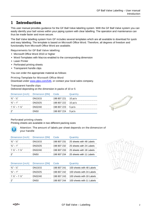
Transparent handle clips
Delivered depending on the dimension in packs of 10 or 5
Dimension [inch] Dimension [DN] Code Quantity
⅜” - ½” DN10/15 198 807 221 10 pc’s
¾” – 1” DN20/25 198 807 222 10 pc’s
1 ¼” – 1 ½” DN32/40 198 807 223 5 pc’s
2” DN50 198 807 224 5 pc’s
Perforated printing sheets
Printing sheets are available in two different packing sizes
Attention: The amount of labels per sheet depends on the dimension of
your handle
Dimension [inch] Dimension [DN] Code Quantity
⅜” - ½” DN10/15 198 807 231 25 sheets with 48 Labels
¾” – 1” DN20/25 198 807 232 25 sheets with 24 Labels
1 ¼” – 1 ½” DN32/40 198 807 233 25 sheets with 18 Labels
2” DN50 198 807 234 25 sheets with 11 Labels
Dimension [inch] Dimension [DN] Code Quantity
⅜” - ½” DN10/15 198 807 241 100 sheets with 48 Labels
¾” – 1” DN20/25 198 807 242 100 sheets with 24 Labels
1 ¼” – 1 ½” DN32/40 198 807 243 100 sheets with 18 Labels
2” DN50 198 807 244 100 sheets with 11 Labels
GF Ball Valve – Labelling 2
Page4
GF Ball Valve Labelling – User manual
Creating a printing template
2 Creating a printing template
Step by step instructions as shown below, ensure labels can be created correctly from the GF printing template in
Microsoft Office Word.
Each printer has individual print parameters and different printing accuracy therefore; to ensure the label
remains within the perforated surface, take a distance of 2mm into account to the edges on each label
If possible use high-resolution graphics for a good printing finish
Using the integrated macros for a quick and easy printing. We recommend using only GF printing
templates, the latest versions are available directly under: www.gfps.com/546
Each perforated sheet may be used only once. It is always recommended to print all fields
GF holds no liability for damage to hardware or software
2.1 Creating a printing template with text and images
To create a printing template all features of Microsoft Word are available. The text fields have been predefined for a
fast text entry. There is the possibility to customise the template and enhance graphics. The following instructions
describe one way to accomplish this.
1. Open the corresponding printing template according to the dimension of the handle
2. Click and override the grey fields for entering text. Format the text
with the Menu-List of Microsoft Word.
GF Ball Valve – Labelling 3
Page5
GF Ball Valve Labelling – User manual
Creating a printing template
3. Inserting graphics: Using Drag and Drop or „Insert“ “Picture“ „Insert“
4. Right-click on the insert picture: “Wrap Text””In Front of Text”.
The picture can now be moved to the favoured position.
5. It is recommended to create one printing template on each sheet.
GF Ball Valve – Labelling 4
Page6
GF Ball Valve Labelling – User manual
Creating a printing template
2.2 Creating a printing template for a standard
There are various standards which describe the marking of non-buried pipelines (e.g. ISO DIN 2403).
A clear identification of the piping system according to the flow medium contributes to the security, the proper
repair and the reduction of operating errors. It should point out hazards to prevent accidents and damage to health.
It is advisable to label non-buried pipes with reasonable intervals at important operations and potentially hazardous
items, such as valves, with the following content:
• Group and supplement colour of the flow medium, according to the relevant standard.
• Flow directions by arrow, with changing direction of flow both directions are indicated.
• Arrow and font colour to the appropriate standard.
• Word indication the flow medium
• Hazard symbol if the flowing medium is covered by the Chemicals Act.
In the following it is shown how such a label can be achieved easily with the GF Ball Valve labelling system.
To be certified, it is recommended to consider the particular standard. No liability is accepted to meet only with the
GF Ball Valve Labelling a standard.
1. Open the corresponding printing template according to the dimension of
the handle.
2. Open the file “Arrow_Template”. The current flow arrows are prepared
as a copy template in the different colours.
3. Choose the right arrows (depending on the medium) and copy it (Ctrl +c)
4. Switch to the open printing template and paste (Ctrl + v) the arrows from the
buffer in the template (if you copy it in a text field proceed as you insert a
picture)
5. Remove one arrowhead by clicking on it, depending on your flow direction.
Adjust the size of the flow arrow and bring it on the desired position.
6. Click on the prescribed text and remove it, fill in your own text. Depending on
the length of the text, you need to adjust the font size.
7. Add hazard symbols as required (see capture “Creating a printing template
with text and images”)
Chlorine
GF Ball Valve – Labelling 5
Page7
GF Ball Valve Labelling – User manual
Printing the template on the printing sheets
3 Printing the template on the printing sheets
For printing without field strips you need to remove the background.
The Microsoft Word templated initialises the perforated fields. These surrounds need to be removed before printing
for a fine print result. For this operation, there are two variants:
Variant 1: Printing by clicking on „Convert into Print version“
As soon as clicked on this function, the surrounds will be removed and the print menu appears. For the printer
settings check the next capture.
Variant 2: Remove Watermark, „Page Layout“ „Watermark“ „Remove Watermark“
Afterwards open “File” “Print”. You then achieve the same result as described in the variant 1.
GF Ball Valve – Labelling 6
Page8
GF Ball Valve Labelling – User manual
Printing the template on the printing sheets
3.1 Recommended printer settings
For a precise print on the perforated printing sheets the following printer settings are recommended:
Paper tray: Multi-purpose Tray
Zoom: 1 page per sheet and no scaling
Depending on the printer further adjustments are still possible, please consider the instruction manual of your
printer.
The printing template has no margins. With a default printer, the following message will appear as soon as the print
command has been executed:
This message can be confirmed by clicking on “Yes”. The relevant printing range of the labels is within the printable
area, so that the labels will be printed correctly.
3.2 Inserting printing sheets into the printer
It is recommended to execute a printing test before printing on the perforated printing sheet. Every perforated
printing sheet has stamped arrows. These are intended to identify the insertion direction of the printing sheet.
Arrows
Dimension / Code number
Execute a printing test, identification of the insertion direction
1. Put on a standard A4-sheet the initial arrows (by hand) and place it in the paper tray of your printer (same
paper tray which you will use for the perforated printing sheets)
2. Open the printing template
3. Go to “File” “Print” and change the settings as recommended ”Print” (Do not delete the background for
the printing test)
4. Compare the initial arrows with the perforated printing sheets. When the lines coincide (pointing in the
same direction) you can place the perforated printing sheets the same way. If the initial lines do not match
proceed with step 5.
5. Use a new A4-sheet and put the initial arrows on it. Insert the sheet twisted by 180° in the paper tray.
6. Reprint the template
7. If the initial arrows point in the same direction, the insertion direction is identified and you can place the
perforated printing sheets the same way.
GF Ball Valve – Labelling 7
Page9
GF Ball Valve Labelling – User manual
Install the label in the ball valve
4 Install the label in the ball valve
The printed labels can be detached from the sheet by hand and installed in the handle of a GF Ball Valve.
1. Remove the black handle clip from the ball valve handle (see figure)
2. Insert the printed label in the handle and install the transparent clip on the lever
3. Keep Black lever clip at safe place, this serves as a maintenance tool for the ball valve
If the printed label appears 180° rotated in the handle, you can lift the handle a little
(do not pull it off) and turn the handle 180° around. Thereby will the ball also be
rotated by 180° (it is not recommended if a special ball is installed). The function of
the ball valve is not affected by turning the ball
For any questions and more information, please contact our local sales companies
or our sales experts.
GF Ball Valve – Labelling 8
Page10
GF Piping Systems
Worldwide at home
Our sales companies and representatives
ensure local customer support in over 100 countries
www.gfps.com
Argentina / Southern South America France Mexico / Northern Latin America Singapore
Georg Fischer Central Plastics Georg Fischer SAS Georg Fischer S.A. de C.V. George Fischer Pte Ltd
Sudamérica S.R.L. 95932 Roissy Charles de Gaulle Cedex Apodaca, Nuevo Leon 11 Tampines Street 92, #04-01/07
Buenos Aires, Argentina Phone +33 (0) 1 41 84 68 84 CP66636 Mexico 528 872 Singapore
Phone +54 11 4512 02 90 fr.ps@georgfischer.com Phone +52 (81) 1340 8586 Phone +65 6747 0611
gfcentral.ps.ar@georgfischer.com www.gfps.com/fr Fax +52 (81) 1522 8906 Fax +65 6747 0577
www.gfps.com/ar mx.ps@georgfischer.com sgp.ps@georgfischer.com
Germany www.gfps.com/mx www.gfps.com/sg
Australia Georg Fischer GmbH
George Fischer Pty Ltd 73095 Albershausen Middle East Spain / Portugal
Riverwood NSW 2210 Australia Phone +49 (0) 7161 302-0 Georg Fischer Georg Fischer S.A.
Phone +61 (0) 2 9502 8000 info.de.ps@georgfischer.com Piping Systems (Switzerland) Ltd 28046 Madrid
australia.ps@georgfischer.com www.gfps.com/de Dubai, United Arab Emirates Phone +34 (0) 91 781 98 90
www.gfps.com/au Phone +971 4 289 49 60 es.ps@georgfischer.com
India gcc.ps@georgfischer.com www.gfps.com/es
Austria Georg Fischer Piping Systems Ltd www.gfps.com/int
Georg Fischer 400 083 Mumbai Sweden
Rohrleitungssysteme GmbH Phone +91 224007 2001 Netherlands Georg Fischer AB
3130 Herzogenburg branchoffice@georgfischer.com Georg Fischer N.V. 117 43 Stockholm
Phone +43 (0) 2782 856 43-0 www.gfps.com/in 8161 PA Epe Phone +46 (0) 8 506 775 00
austria.ps@georgfischer.com Phone +31 (0) 578 678 222 info.se.ps@georgfischer.com
www.gfps.com/at Indonesia nl.ps@georgfischer.com www.gfps.com/se
George Fischer Pte Ltd – www.gfps.com/nl
Belgium / Luxembourg Representative Office Switzerland
Georg Fischer NV/SA Phone +62 21 2900 8564 Norway Georg Fischer
1070 Bruxelles/Brüssel Fax +62 21 2900 8566 Georg Fischer AS Rohrleitungssysteme (Schweiz) AG
Phone +32 (0) 2 556 40 20 sgp.ps@georgfischer.com 1351 Rud 8201 Schaffhausen
be.ps@georgfischer.com www.gfps.com/sg Phone +47 67 18 29 00 Phone +41 (0) 52 631 30 26
www.gfps.com/be no.ps@georgfischer.com ch.ps@georgfischer.com
Italy www.gfps.com/no www.gfps.com/ch
Brazil Georg Fischer S.p.A.
Georg Fischer Sist. de Tub. Ltda. 20063 Cernusco S/N (MI) Philippines Taiwan
04571-020 São Paulo/SP Phone +39 02 921 861 George Fischer Pte Ltd Georg Fischer Co., Ltd
Phone +55 (0)11 5525 1311 it.ps@georgfischer.com Representative Office San Chung Dist., New Taipei City
br.ps@georgfischer.com www.gfps.com/it Phone +632 571 2365 Phone +886 2 8512 2822
www.gfps.com/br Fax +632 571 2368 Fax +886 2 8512 2823
Japan sgp.ps@georgfischer.com www.gfps.com/tw
Canada Georg Fischer Ltd www.gfps.com/sg
Georg Fischer Piping Systems Ltd 556-0011 Osaka, United Kingdom / Ireland
Mississauga, ON L5T 2B2 Phone +81 (0) 6 6635 2691 Poland George Fischer Sales Limited
Phone +1 (905) 670 8005 jp.ps@georgfischer.com Georg Fischer Sp. z o.o. Coventry, CV2 2ST
Fax +1 (905) 670 8513 www.gfps.com/jp 05-090 Sekocin Nowy Phone +44 (0) 2476 535 535
ca.ps@georgfischer.com Phone +48 (0) 22 31 31 0 50 uk.ps@georgfischer.com
www.gfps.com/ca Korea poland.ps@georgfischer.com www.gfps.com/uk
GF Piping Systems www.gfps.com/pl
China Georg Fischer Korea Co., Ltd. USA / Caribbean
Georg Fischer Piping Systems Ltd Unit 2501, U-Tower Romania Georg Fischer LLC
Shanghai 201319 120 HeungdeokJungang-ro (Yeongdeok-dong) Georg Fischer 9271 Jeronimo Road
Phone +86 21 3899 3899 Giheung-gu, Yongin-si, Gyeonggi-do, Korea Piping Systems (Switzerland) Ltd 92618 Irvine, CA
china.ps@georgfischer.com Phone: +82 31 8017 1450 020257 Bucharest - Sector 2 Phone +1 714 731 88 00
www.gfps.com/cn Fax : +82 31 217 1454 Phone +40 (0) 21 230 53 80 Fax +1 714 731 62 01
kor.ps@georgfischer.com ro.ps@georgfischer.com us.ps@georgfischer.com
Denmark / Iceland www.gfps.com/kr www.gfps.com/int www.gfps.com/us
Georg Fischer A/S
2630 Taastrup Malaysia Russia International
Phone +45 (0) 70 22 19 75 George Fischer (M) Sdn. Bhd. Georg Fischer Georg Fischer
info.dk.ps@georgfischer.com 40460 Shah Alam, Selangor Darul Ehsan Piping Systems (Switzerland) Ltd Piping Systems (Switzerland) Ltd
www.gfps.com/dk Phone +60 (0) 3 5122 5585 Moscow 125040 8201 Schaffhausen/Switzerland
Fax +603 5122 5575 Phone +7 495 748 11 44 Phone +41 (0) 52 631 30 03
Finland my.ps@georgfischer.com ru.ps@georgfischer.com Fax +41 (0) 52 631 28 93
Georg Fischer AB www.gfps.com/my www.gfps.com/ru info.export@georgfischer.com
01510 VANTAA www.gfps.com/int
Phone +358 (0) 9 586 58 25
Fax +358 (0) 9 586 58 29
info.fi.ps@georgfischer.com
www.gfps.com/fi
The technical data are not binding. They neither constitute expressly
warranted characteristics nor guaranteed properties nor a guaranteed durability.
They are subject to modification. Our General Terms of Sale apply.
GFDO_6457_4 (08.16)
© Georg Fischer Piping Systems Ltd
CH-8201 Schaffhausen/Switzerland, 2016