


Chemical conveyance
The analyzed case represents an exemplary system for the transport of
chemicals in an aluminium pickling plant.
The system is designed in the dimension d63 and installed in Leipzig (Germany).
Flange connections and infrared welding are used for the jointing.
このカタログについて
| ドキュメント名 | Environmental Product Declaration:PP System |
|---|---|
| ドキュメント種別 | 製品カタログ |
| ファイルサイズ | 678.4Kb |
| 取り扱い企業 | ジョージフィッシャー株式会社 (この企業の取り扱いカタログ一覧) |
この企業の関連カタログ


このカタログの内容
Page1
Environmental
Product Declaration
PP-System According to EN 15804
Chemical conveyance Georg Fischer Piping Systems Ltd. Ebnatstrasse 111
CH-8201 Schaffhausen
1. Declaration of general information +41 (0)52 631 11 11
www.gfps.com/sustainability
1.1 Introduction sustainability.ps@georgfischer.com
GF Piping Systems is one of the three divisions within Georg Fischer
Corporation and a leading provider of plastic and metal piping systems
with global market presence. The product portfolio includes pipes,
fittings, valves and the corresponding automation and jointing
technology for industry, building technology as well as water and gas
utilities. Georg Fischer Piping Systems proactively incorporates its
environmental responsibility into its everyday business activities.
Because we understand environmental awareness as one of the
corporation‘s core values, internal structures and processes are geared
towards sustainability. In this context, life cycle assessments are the
correct tool to gain insight in the different life cycle phases of our
systems.
This EPD is based on a detailed background report written by the
Flemish Institute for technological research (Vito). The report is in line
with EN 15804 “Sustainability of construction works – environmental
product declarations – Core rules for the product category of
construction products”. The data of the study complies with the quality
requirements set out in EN 15804 (EN 15804+A1:2013, Sustainability of
construction works - Environmental product declarations - Core rules
for the product category of construction products). Data regarding the
production of the pipe system components is company specific and was
provided by GF Piping Systems.
Declaration
Declaration owner & Program Georg Fischer Piping
operator’s name Systems Ltd.
Validity 01.06.2014 – 31.05.2019
Declaration Number GFPS-EPD_1406-4_4
EPD-Type Cradle to grave
Data calculated by Vito NV (Flemish Institute for
technological research)
www.vito.be
Life Cycle Inventory (LCI) source Ecoinvent v 2.2 (2010,
for generic background processes updated August 2012)
Software SimaPro 7.3.3
Page2
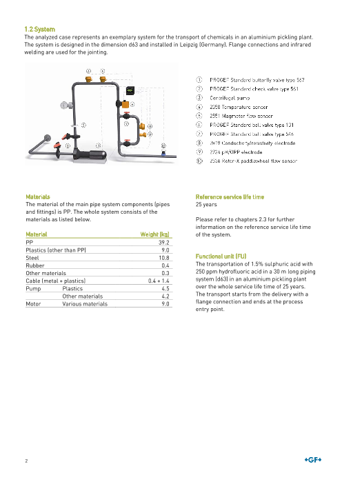
1.2 System
The analyzed case represents an exemplary system for the transport of chemicals in an aluminium pickling plant.
The system is designed in the dimension d63 and installed in Leipzig (Germany). Flange connections and infrared
welding are used for the jointing.
Materials Reference service life time
The material of the ma in pipe system components (pipes 25 years
and fittings) is PP. The whole system consists of the
materials as listed below. Please refer to chapters 2.3 for further
information on the reference service life time
Material Weight (kg) of the system.
PP 39.2
Plastics (other than PP) 9.0
Steel 10.8 Functional unit (FU)
Rubber 0.4 The transportation of 1.5% sulphuric acid with
Other materials 0.3 250 ppm hydrofluoric acid in a 30 m long piping
Cable (metal + plastics) 0.4 + 1.4 system (d63) in an aluminium pickling plant
Pump Plastics 4.5 over the whole service life time of 25 years.
Other materials 4.2 The transport starts from the delivery with a
Motor Various materials 9.0 flange connection and ends at the process
entry point.
2
Page3
Components of the system (number of pieces or meter)
The system mainly consists of Georg Fischer Piping Systems components. However, to complete the system also
external components (Ext.) are necessary which are not produced by Georg Fischer Piping Systems. The calculation
of the environmental impact of these products is based on publicly available data and assumptions.
Product Code Pieces or meter Material
System components
PROGEF Standard pipe, d63 167480716 30 m PP-H
PROGEF Standard tee 90° equal, d63 727208511 3 PP-H
PROGEF Standard elbow 90°, d63 727108511 6 PP-H
PROGEF Standard union, d63 727518511 4 PP-H
PROGEF Standard reducer, d63/d32 727908560 1 PP-H
PROGEF Standard socket equal, d63 727910111 8 PP-H
PROGEF Standard flange adaptor, d63 727798711 10 PP-H
Backing flange, d63 727700411 10 PPGF30
O-Ring gasket, d63 748410013 6 EPDM
PROGEF Standard butterfly valve type 567, d63 167567802 2 PP-H (body) and others
PROGEF Standard check valve type 561, d63 167561087 1 PP-H (body) and others
PROGEF Standard ball valve type 131, d63 199131368 1 PP-H (body) and others
PROGEF Standard ball valve type 546, d63 167546447 2 PP-H (body) and others
2350 Temperature sensor 159000920 1 PVDF (sensor housing) and others
2551 Magmeter flow sensor 159001110 2 PP (sensor body) and others
2819 Conductivity/resistivity electrode 198844010 1 Stainless steel (electrode) and
others
2724 pH/ORP electrode 159001545 1 PPS (sensor body) and others
2536 Rotor-X paddlewheel flow sensor 198840143 1 PPGF30 (sensor body) and others
8900 Multi parameter controller 159000868 1 PBT (housing) and others
PROGEF Standard gauge guard type Z700 199041003 1 PP-H (body) and others
Centrifugal pump Ext. 1 Various metals and others
Cable Ext. 36.2 m Copper and others
Components for installation
Bolts Ext. 40 Stainless steel
Nuts Ext. 64 Stainless steel
Washers Ext. 64 Stainless steel
Brackets Ext. 25 PP
1.3 Comparability
EPDs of construction products may not be comparable if they do not comply with the EN 15804.
1.4 Demonstration of verification
3
Page4
2. Declaration of environmental parameters derived from LCA
2.1 Flow diagram of the processes included in the LCA
Product stage Use stage
End of life A1: Raw material supply B1: Use *
stage A2: Transport B2: Maintenance ** C1: De-
A3: Manufacturing B3: Repair ** construction/
Construction-installation A B4: Replacement ** B Demolition ** C
process B5: Refurbishment ** C2: Transport
A4: Transport to installation B6: Operational C3: Waste
A5: Installation energy use processing
B7: Operational water C4: Disposal
use *
* Stage not relevant, ** Environmental impact below cut-off criteria. Please refer to chapter 2.3 for details.
2.2 Parameters describing environmental impacts
Photo- Abiotic
Acidification chemical depletion Abiotic
Global Ozone of soil and Eutro- ozone - non depletion
Impact category warming depletion water phication creation fossil - fossil
kg CO2 eq kg CFC-11 eq kg SO2 eq kg PO
3-
4 eq kg C2H4 eq kg Sb eq MJ
A1-3 Product stage 4.22E+02 2.17E-03 3.04E+00 4.85E-01 1.74E-01 5.42E-02 6.41E+03
Transport to
A4 3.14E+01 4.16E-06 1.32E-01 2.40E-02 5.10E-03 3.68E-05 4.39E+02
installation
A5 Installation 4.38E+00 2.79E-07 9.63E-03 2.46E-03 1.41E-01 1.48E-05 6.47E+01
Use, Maintenance,
Repair, Replace-
B1-5 0 0 0 0 0 0 0
ment, Refurbish-
ment
Operational energy 6.57E+04 3.10E-03 2.67E+02 3.85E+01 1.20E+01 1.72E-01 7.57E+05
B6
use
Operational water
B7 0 0 0 0 0 0 0
use
De-construction/
C1 0 0 0 0 0 0 0
Demolition
Transport to end-
C2 4.61E+00 7.24E-07 2.54E-02 5.22E-03 7.61E-04 2.99E-05 6.73E+01
of-life treatment
C3 Waste processing 2.61E+02 2.21E-07 3.08E-02 6.67E-03 1.13E-03 1.02E-05 2.83E+01
C4 Disposal 0 0 0 0 0 0 0
4
Page5
2.3 Scenarios and additional technical information
The analyzed case represents an exemplary system for the transport of chemicals in an aluminium pickling plant.
Product stage
The production of the plastic raw material was modeled by generic European data (source: ecoinvent) and
A1 complemented by specific data from GF Piping Systems to consider the company specific formulation of the raw
material.
Wherever possible, the specific transport distances were taken into account. Data from ecoinvent with the
A2
respective parameters was used to model the transportation.
The use of energy is the most important input for this process step. Pipes are extruded while fittings and valve
parts are injection moulded. Each of GF Piping Systems’ worldwide production sites is certified according to ISO
14001 (Environmental management systems) and to OHSAS 18001 (Occupational health and safety management
A3
systems) or is currently in the certification process. For the production of GF Piping Systems components,
electricity mixes for the respective country/continent was used. The production of external products was modeled
using generic ecoinvent data records for the process.
Construction process
The system is installed in Leipzig (Germany).
Pipes are transported over a distance of 350 km by means of a truck. Valves and measuring instruments are first
transported to storage: measuring instruments via air freight (ecoinvent data record: Transport, aircraft, freight,
intercontinental, RER U) over 5 000 km; valves via truck over 150 km. Afterwards these components as well as
A4
fittings, bolts, nuts, washers and brackets are transported to the installation site by truck over 600 km. The pump
and the gauge guard are also transported by truck over 480 km and 540 km respectively to the installation site.
For all transportations via truck the ecoinvent data record “Transport, lorry > 16 t, fleet average/RER U) was used.
Loading capacity is 60%.
For the installation of the whole system 1.8 kWh welding energy is needed (Electricity, low voltage, production
RER, at grid/RER U).
Outputs of the complete installation of the system are PP pipe cut-off (0.2 kg/FU) and packaging waste (3.9 kg/FU)
A5
whereof 88% is cardboard. Wood and cardboard are recycled; PE film, nylon belts and PP straps are incinerated.
Transport distance to recycling is assumed to be 600 km, transport to incineration is 150 km. Transport is carried
out by truck.
Use stage
There are no further environmental impacts arising from the use of the systems. This stage is considered as not
B1
relevant.
The system is designed to be operated without repair, maintenance, replacement or refurbishment during the
reference service life time. This is subject to the condition that the system is operated according to the
specifications given by GF Piping Systems.
B2-B5 The lifetime of a valve is mainly influenced by the actuation cycles. The number of actuation cycles the valves are
tested for is not reached during the life time of the evaluated system. It is possible that in individual cases
components of the valve (e.g. seals) must be replaced. In this case the environmental impact is negligible
compared to the impact of the whole system and below the cut-off criteria defined in EN 15804.
The operational use of the system is an important stage mainly because of the long reference service life time of
B6 25 years. 117 000 kWh of energy (ecoinvent dataset: Electricity, low voltage, production RER, at grid/RER U) per
functional unit is necessary to run the pump.
B7 No operational water use is necessary for the system. This stage is considered as not relevant.
End of life stage
A small energy input is needed to cut the pipe into smaller pieces. The environmental impact is negligible
C1
compared to the impact of the whole system and below the cut-off criteria defined in EN 15804.
Transportation to the end of life treatment facilities is carried out by truck. Distances are 600 km for recycling and
C2
150 km for incineration.
It is assumed that all metal parts are recycled and all other parts are incinerated with energy recovery. The
exported energy is in the form of electricity and thermal energy. Approximately 11.5% of the net energy content of
C3 the incinerated waste is converted to electricity and 23.4% is converted to heat. Both are sold to external
consumers. These values reflect the situation in Swiss municipal waste incinerators about 10 years ago, as
reported in ecoinvent documentation.
It is assumed that all metal parts are recycled and all other parts are incinerated with energy recovery. Therefore
C4
module C4 is not relevant.
5
Page6
Reference service life data
Parameter Data
Reference Service Life 25 years
System components are compliant with relevant international standards, e.g.
• EN (European Standards)
• ISO (International Organization for Standardization)
• DVS (German Welding Society)
• DIN (German Institute for Standardization)
Declared product
properties Most relevant standards are:
ISO 15494 Plastics piping systems for industrial applications - Polybutene (PB), Polyethylene
(PE) and Polypropylene (PP) - Specifications for components and the system
ISO 16138 Industrial valves -- Diaphragm valves of thermoplastics materials
ISO 16135 Industrial valves -- Ball valves of thermoplastics materials
PP characteristics Value Test standard
Operating temperature range -10 °C to + 95 °C
Density 0.90 - 0.91 g/cm3 EN ISO 1183 - 1
Yield Stress at 23 °C 31 N/mm2 EN ISO 527 - 1
Tensile e-modulus at 23 °C 1300 N/mm2 EN ISO 527 - 1
Charpy notched impact strength at 23 °C 85 kJ/m2 EN ISO 179 – 1/1eA
Charpy notched impact strength at 0 °C 4.8 kJ/m2 EN ISO 179 – 1/1eA
Ball indentation hardness (132N) 58 MPa EN ISO 2039 - 1
Design application Heat distortion temperature HDT B 95 °C EN ISO 75 - 2
parameters 0.45 MPa
Crystallite melting point 150 °C - 167 °C DIN 51007
Heat conductivity at 23 °C 0.23 W/m K EN 12664
Water absorption at 23 °C 0.1% EN ISO 62
Limited oxygen index (LOI) 19% ISO 4589 - 1
For more information, please refer to the planning fundamentals which are available at:
gfps.com > Support & Services > Planning Assistance > Planning Fundamentals > Industrial Piping
Systems
• Wide operating temperature range
• High chemical resistance
Assumed quality of work
• No corrosion and no incrustation reduces maintenance to a minimum
Indoor environment The system is installed in Leipzig, Germany. Standard indoor conditions apply.
• SDR 11
• PN 10
Usage conditions
• Flow rate 2 m/s
The system is designed to be operated without repair, maintenance, replacement or refurbishment.
This is subject to the condition that the system is installed and operated according to the
Maintenance
specifications given by GF Piping Systems.
6
Page7
2.4 Parameters describing resource use
Product Construction
Parameters describing resource use, primary energy Use stage End of life
stage process stage
A1-3 A4 A5 B1-B5 B6 B7 C1 C2 C3 C4
Use of renewable primary energy excluding
renewable primary energy resources used as raw 4.33E+02 2.62E+00 2.49E+00 0 1.18E+05 0 0 1.54E+00 1.59E+00 0
materials
Use of renewable primary energy resources used as
6.24E+01 0 8.92E-02 0 0 0 0 0 0 0
raw materials
Total use of renewable primary energy resources
(primary energy and primary energy resources used 4.96E+02 2.62E+00 2.58E+00 0 1.18E+05 0 0 1.54E+00 1.59E+00 0
as raw materials)
Use of non-renewable primary energy excluding non-
renewable primary energy resources used as raw 5.94E+03 4.52E+02 6.66E+01 0 1.27E+06 0 0 7.46E+01 3.65E+01 0
materials
Use of non-renewable primary energy resources
1.79E+03 0 7.22E+00 0 0 0 0 0 0 0
used as raw materials
Total use of non-renewable primary energy
resources (primary energy and primary energy 7.73E+03 4.52E+02 7.38E+01 0 1.27E+06 0 0 7.46E+01 3.65E+01 0
resources used as raw materials)
Parameters describing resource use, secondary Product Construction
materials and fuels, and use of water Use stage End of life stage process stage
A1-3 A4 A5 B1-B5 B6 B7 C1 C2 C3 C4
Use of secondary material* kg 0 0 0 0 0 0 0 0 0 0
Use of renewable secondary
MJ, net calorific value 0 0 0 0 0 0 0 0 0 0
fuels*
Use of non-renewable
MJ, net calorific value 0 0 0 0 0 0 0 0 0 0
secondary fuels*
Net use of fresh water m3 4.85E+00 5.80E-02 1.67E-02 0 5.21E+02 0 0 2.03E-02 1.28E-01 0
*Only for foreground process from which LCI data are made available by GF Piping Systems - the number does not include processes and materials modelled by
means of background data, e.g. transportation, electricity, ancillary materials, etc.
7
MJ, net calorific value
Total (of product stage) Total (of product stage)
Transport Transport
Construction installation Construction installation
process process
Use , Maintenance, Repair, Use, Maintenance, Repair,
Replacement, Refurbishment Replacement, Refurbishment
Operational energy use Operational energy use
Operational water use Operational water use
De-construction / Demolition De-construction / Demolition
Transport Transport
Waste processing Waste processing
Disposal Disposal
Page8
2.5 Environmental information describing output flows
Other environmental information describing output Product Construction Use stage End of life
flows stage process stage
A1-3 A4 A5 B1-B5 B6 B7 C1 C2 C3 C4
Components for re-use* kg 0 0 0 0 0 0 0 0 0 0
Materials for recycling* kg 4.09E+00 0 3.87E+00 0 0 0 0 0 2.24E+01 0
Materials for energy recovery* kg 0 0 0 0 0 0 0 0 0 0
MJ per energy
Exported energy - electricity* 1.53E+00 0 1.14E+00 0 0 0 0 0 2.03E+02 0
carrier
Exported energy - thermal MJ per energy
3.23E+00 0 2.22E+00 0 0 0 0 0 1.26E+01 0
energy* carrier
*Only for foreground process from which LCI data are made available by GF Piping Systems - the number does not include processes and materials modelled by
means of background data, e.g. transportation, electricity, ancillary materials, etc.
Other environmental information describing waste Product Construction
Use stage End of life
categories stage process stage
A1-3 A4 A5 B1-B5 B6 B7 C1 C2 C3 C4
Hazardous waste disposed 6.61E-02 2.52E-04 5.26E-05 0 1.56E+00 0 0 7.41E-05 1.93E-04 0
Non-hazardous waste disposed kg 1.33E+02 8.06E-01 1.85E-01 0 1.90E+03 0 0 4.84E-01 5.49E+00 0
Radioactive waste disposed 1.50E-02 1.77E-04 1.46E-04 0 7.25E+00 0 0 9.88E-05 1.15E-04 0
8
Total (of product stage) Total (of product stage)
Transport Transport
Construction installation Construction installation
process process
Use , Maintenance, Repair, Use, Maintenance, Repair,
Replacement, Refurbishment Replacement, Refurbishment
Operational energy use Operational energy use
Operational water use Operational water use
De-construction / Demolition De-construction / Demolition
Transport Transport
Waste processing Waste processing
Disposal Disposal
Page9
9