


このカタログについて
| ドキュメント名 | Metis M309 / M316 /M318 |
|---|---|
| ドキュメント種別 | 製品カタログ |
| ファイルサイズ | 1.6Mb |
| 取り扱い企業 | Process Sensors Corporation (この企業の取り扱いカタログ一覧) |
この企業の関連カタログ


このカタログの内容
Page1
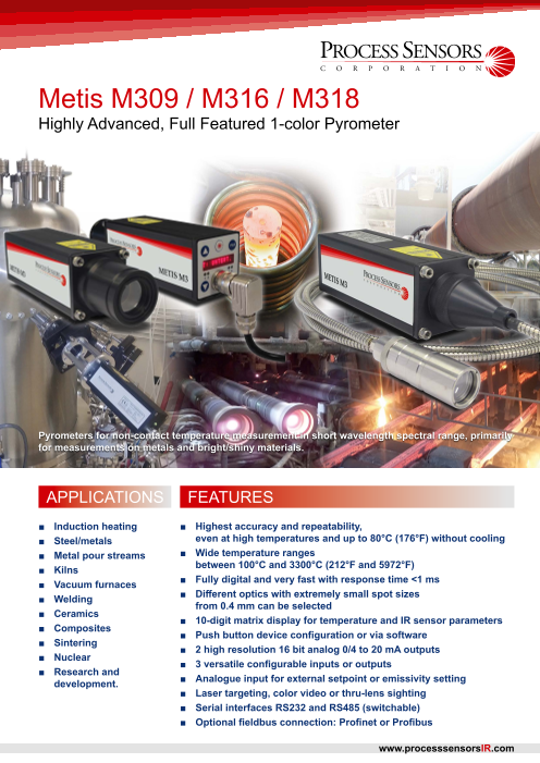
Metis M309 / M316 / M318
Highly Advanced, Full Featured 1-color Pyrometer
Pyrometers for non-contact temperature measurement in short wavelength spectral range, primarily
for measurements on metals and bright/shiny materials.
APPLICATIONS FEATURES
■ Induction heating ■ Highest accuracy and repeatability,
■ Steel/metals even at high temperatures and up to 80°C (176°F) without cooling
■ Metal pour streams ■ Wide temperature ranges
■ Kilns between 100°C and 3300°C (212°F and 5972°F)
■ Vacuum furnaces ■ Fully digital and very fast with response time <1 ms
■ Welding ■ Different optics with extremely small spot sizes
from 0.4 mm can be selected
■ Ceramics ■ 10-digit matrix display for temperature and IR sensor parameters
■ Composites ■ Push button device configuration or via software
■ Sintering ■ 2 high resolution 16 bit analog 0/4 to 20 mA outputs
■ Nuclear ■ 3 versatile configurable inputs or outputs
■ Research and
development. ■ Analogue input for external setpoint or emissivity setting
■ Laser targeting, color video or thru-lens sighting
■ Serial interfaces RS232 and RS485 (switchable)
■ Optional fieldbus connection: Profinet or Profibus
www.processsensorsIR.com
Page2
Technical Data
Model M309 M316 M318
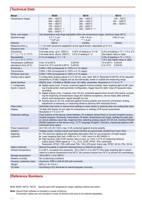
Temperature ranges 550 – 1400°C 200 – 1300°C 100 – 700°C
600 – 1600°C 250 – 1300°C 150 – 1200°C
650 – 1800°C 350 – 1800°C 180 – 1300°C
750 – 2500°C 400 – 2500°C
900 – 3000°C *) 500 – 3300°C **)
1000 – 3300°C *)
Temp. sub ranges Any temperature sub-range adjustable within the temperature range (minimum span 50°C)
Spectral range 0.7–1.1 µm 1.45–1.8 µm 1.65–2.1 µm
*) 0.87 µm **) 1.4 µm
Detector Silicon InGaAs InGaAs
Response time t90 < 1 ms (with dynamical adaptation at low signal levels), adjustable up to 10 s
Exposure time < 0.5 ms
Uncertainty Full-scale temp. up to 2500°C: 0.25% of reading in °C+1K 0.4% of reading in °C + 1 K or 2°C
(ε = 1, t90 = 1s, TA = 23°C) Full-scale temp. above 2500°C: 0.5% of reading in °C (the higher value is valid)
Repeatability 0.1% of reading in °C + 1 K 0.2% of reading in °C + 1 K or
(ε = 1, t90 = 1s, TA = 23°C) 1.6°C (the higher value is valid)
Temperature coefficient From 10 to 60°C: 0.02%/K 10 to 60°C: 0.02%/K
(deviations from 23°C) From 0 to 10°C and 60 to 80°C: 0.04%/K 0 to 10°C: 0.04%/K
Emissivity ε 0.050–1.200 (corresponds 5–120% in 0.1% steps)
Transmission 0.050–1.000 (corresponds 5–100% in 0.1% steps)
Fill factor spot size 0.050–1.000 (corresponds 5–100% in 0.1% steps)
Analog output signal 2 configurable analog outputs 0 or 4–20 mA, max. load: 500 Ω. Resolution 0.0015% of the adjusted
temperature (16 Bit). Outputs can be set individually, inside or outside the measuring range.
Serial interface RS232 (max. 115 kBd) or RS485 (max. 921 kBd), switchable. Resolution 0.1°C or 0.1°F
3 configurable ■ Digital inputs (max. 3 inputs, protected against reverse polarity): laser targeting light on/off, clear-
Inputs / outputs ing of peak picker, load pyrometer configuration, trigger input for start / stop of measured value
recording.
■ Digital outputs (max. 3 outputs, max. 50 mA, protected against short circuit): limit switch, exceed-
ing the beginning of temperature range (for material recognition), device ready after self-test,
device over-temperature, signal strength too low.
■ Analog input (0–20 mA, protected against reverse polarity and incorrect connection): analog
adjustment of emissivity, or measuring distance (devices with motorized focus).
Peak picker Automatic hold mode or manual time settings to clear (reset) or external clear via configurable input
Display 10-digit LED display (5 mm high) for temperature or settings of IR sensor parameters
Resolution 0.1°C or 0.1°F
Parameter settings Push buttons on the device, serial interface, PC software SensorTools or via self-compiled commu-
nication program: Emissivity, transmission, fill factor, temperature sub range, settings for peak pick-
er, device address, baud rate, response time, selecting analog outputs 0/4–20 mA, interface RS232/
RS485 (selection on the device only), °C/°F, language (English / German), measuring distance with
motorized focus optics.
Power requirement 24 V DC (18–30 V DC), max. 6 VA; protected against reverse polarity
Isolation Voltage supply, analog outputs and serial interface are galvanically isolated from each other
Sightings ■ Thru-the-lens sighting with adjustable attenuation filter for eye protection of bright targets
(optional) ■ Laser targeting light (red, λ=650 nm, P< 1 mW, class II to IEC 60825-1)
■ High dynamic color CCD camera, field of view: ca. 3.6% x 2.7% of measuring distance
output signal: FBAS signal ca. 1 VPP, 75 Ω, CCIR, NTSC / PAL switchable
Resolution: NTSC: 720 x 480 pixel; PAL: 720 x 576 pixel; frame rate: NTSC: 60 Hz, PAL: 50 Hz
Optics (optional) Manual focusable or optional motorized focus or fixed focus optics
Ambient temperature 0 to 80°C, focusable lens assembly: -20 to 250°C (-4 to 482°F) (The laser targeting light is deacti-
vated at a device temperature from 60°C, the camera module from 55°C to prevent its overheating)
Storage temperature -20 to 85°C (-4 to 185°F)
Relative humidity No condensing conditions
Housing / protection class Aluminum, IP65 to DIN 40 050 with connector
Weight 650 g (1 lb. 6.9 oz.)
CE label According to EU directives for electromagnetic immunity
Reference Numbers
Metis M309 / M316 / M318 Specify each with temperature range, sighting method and optics
Note: SensorTools software is included in scope of delivery,
Connection cables are not included in scope of delivery and have to be ordered separately.
- 2 -
Page3
Power Up and Measure Temperature
In principle the M3 series only requires connection to a power supply to start a measurement.
Metis M3 pyrometers are stand alone, self contained IR thermometers with direct outputs for easy integration in nearly all applica-
tion environments.
The short-wave spectral ranges of the various models are specially designed for accurate temperature measurements of metals
and other bright, reflective materials.
The models M309, M316 and M318 differ in their spectral ranges and associated in their ranges.
The material to be measured largely determines which spectral range of the pyrometer should be selected. For metal measure-
ments, the shortest possible spectral range for a precise measurement is advantageous. Due to technical reasons the beginning
of a temperature range may be limited, to a higher starting temperature therefore a model must be selected with a slightly higher
spectral range, e.g. longer wavelength.
Features
Proven Sighting:
■ More precise laser target marking
■ Enhanced view finder
■ New high dynamic color camera module
Clear Device Operation:
■ Large, bright 10 digit display
■ All measurement settings directly on the device
■ LEDs for the display of active limit outputs
■ Simple setting of the measuring distance with motor focus
Fast, Accurate Outputs:
■ Serial high-speed interface up to 921 kBaud
■ 2 high resolution 16 bit analog 0/4 to 20mA outputs
A Variety of Models:
■ Motorized focus optics
■ Optics with manual adjustment of focus
■ Fixed focus optics for smallest spot sizes
■ Fiber optic version with small optical heads
Harsh Environmental Conditions:
■ Advanced ambient temperature up to 80°C
Additional Equipment: ■ Fiber optic models up to 250°C (optics and fiber optic cable)
■ Fieldbus interfaces: ■ With Sapphire protection window (devices with integrated
Profinet, Profibus optics)
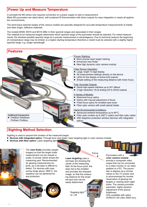
Sighting Method Selection
Sighting is used to pinpoint the location of the measured target.
■ Devices with integrated optics: Through lens view finder, laser targeting light or color camera module
■ Devices with fiber optics: Laser targeting light
The view finder provides upright
imagery so that the target under Focus
measurement can be viewed vi- Pyrometers with a
sually. A circular reticle shows the Laser targeting uses a color camera module
measuring spot. Recommended red laser dot showing the provide a composite video
for glowing measurement ob- center of the measuring output that can be connected
jects, as a red laser is difficult to field. At the focus point, the to a video monitor or via video
detect. For devices with mea- laser dot is the smallest grabber to a PC. The pyrom-
suring range above 1800°C, the and provides the sharpest eter is aligned via a circular
eyepiece can be darkened for image, so that the measur- reticle on the TV screen and
eye protection. ing distance for the small- is recommended for remote
est spot size can be observation of glowing hot
easily determined. targets or viewing down sight
tubes. The camera provides
automatic, highly dynamic
adjustment of the picture
Targeting light brightness.
on / off Only available with optics
OV09-D1/-D2 (340–4000 mm).
- 3 -
Page4
Intelligent Installation Possibilities
J Serial Interface RS232 or RS485 (Selectable)
Via serial interface, the pyrometer communicates with other digital devices such as a PLC, computer with free SensorTools software
or a self-written communication software program. Measured values can be recorded and device parameters can be set directly on
the device, via SensorTools software or serial interface RS232 or RS485.
■ RS232 for short distances to the PC. Transfer rates of max. 115 kB
■ RS485 for long distance connection. Max. of 921 kB, use in bus configuration.
An interface converter RS232 or RS485 to USB (accessory) allows for easy connection to a PC.
J 2 Analog Outputs
Each of the high-resolution analog outputs can be used for independent devices with 0/4-20 mA inputs, e.g. to connect additional
temperature displays or other devices.
By “scalable” it is meant that the temperature range assigned to the analog outputs can be adapted to the specific application,
allowing reduction or expansion of the range as needed when integrating the sensor into an existing system.
J 3 Configurable Inputs / Outputs
3 pyrometer connectors are available as digital input, digital output or analog input:
■ Each digital output switches a low voltage output active or inactive (NC or NO, ad-
justable) with several selectable states (Rear panel LEDs indicate the switching state):
• Limit switch for decreasing or exceeding a certain temperature threshold
• Material detection (exceeding the beginning of temperature range)
• Device state (device is ready for operation)
• Over temperature, if the maximum allowed device temperature is exceeded
• Signal strength is too low (dirty window alarm)
■ Each digital input can be connected to an external contact closure and configured for a function:
• Laser targeting light on and off
• Manually delete (reset) of maximum value storage
• Start / stop recording of measured values via the SensorTools software
• Up to 7 pyrometer configurations can be saved and retrieved
■ Using the analog input (available soon and to install via firmware update) a current can be fed for
• Analog specification of the emissivity
J Ambient Temperature
The devices of the M3 series are designed with a very small temperature coefficient for ambient temperatures up to 80°C. Thus,
many new applications can be entered and solved without external cooling equipment. To maintain the accuracy, M318 models
should be used only up to 60°C ambient temperature due to the low initial temperature measurement.
J Material Properties
The entry options for material settings have been simplified:
■ Emissivity: Each material has a max. emissivity of 1.00 which can be set, an adjustment up to 1.20 can be used. The emissivity
adjustment above 1.00 allows for temperature corrections due to higher background reflection.
■ Transmittance: For measurements through windows signal losses occur by transmission of the window. This value is included
with each window and can be entered easily.
J Maximum Value Storage (Peak Picker)
The maximum value storage is a useful feature when the measured object appears only briefly in the pyrometer’s field of view, or to
capture peak temperatures while measuring a series of objects. The hottest value of the measured object is stored and disregards
temperature valleys, e.g. steel surfaces with scale in hot rolling mill application. The maximum value can be reset automatically or
manually or by a selectable clear time.
J Fieldbus Systems
Optional pyrometer control can be done with
■ Profinet or Profibus
- 4 -
Page5
Device Designs / Optics
The following tables show the optical data of the different device types. For reliable measurement the measurement object should
be at least as large as the spot size.
Values in the optics tables illustrate the focused measuring distances and respective spot sizes. The spot size diameter for distanc-
es not given in the table can be interpolated.
The pyrometer can be used at distances other than its’ focal distance, however the spot size is generally larger and therefore the
target size must be larger.
Focusable optics (manual or motorized focus) can be continuously adjusted within the minimum and maximum specified mea-
surement distance, providing the smallest possible spot size diameter at that focus distance.
Fixed focus optics are factory-set to a certain measurement distance reaching there the smallest possible spot size. The robust
and precise design provides minimal axial deviations between mechanical and optical axis. This alignment is maintained even the
device is rotated, useful in measurements through long sighting tubes.
The pyrometer must be properly aligned to the measurement
object to detect the temperature correctly. In the focus point of the
lens (focal distance) the spot size diameter is smallest. Measure-
ments out of the focus distance are also possible (in front of or
behind the focus distance) to determine the average temperature optics
ce
of a bigger spot. sable istan ) Aperture Ø
Focu ing dr ustable
asu dj
Integrated Optics (manually adjusted or motorized focus) Me a
epless
- with sighting method laser targeting light or view finder Spot size Ø (st
Optics Measuring Spot size M [mm] Aperture Ø
(focusable) distance M309 (all ranges) D [mm]
a [mm] M316 ( all ranges)
M318 (100–700°C) M318 ( 150–1200°C
adjustable 180–1300°C)
from 130 mm 0.6 mm 0.4 mm
OM09-A0 ... 160 mm 0.8 mm 0.5 mm Manual
to 200 mm 1.1 mm 0.65 mm Focus
from 190 mm 0.8 mm 0.5 mm
... 1. Turn counterclockwise
OM09-B0 300 mm 1.4 mm 0.9 mm 16 mm 2. Pull / push in
to 420 mm 2 mm 1.3 mm (FSC≤1400°C) 3. Lock turn clockwise
from 340 mm 1.3 mm 0.8 mm
500 mm 2.3 mm 1.3 mm 8 mm
OM09-C0 700 mm 3.3 mm 2 mm (FSC>1400°C)
... 1000 mm 4.5 mm 2.9 mm Motor focus
a:1
2000 mm 10.5 mm 6.1 mm 500mm
- Via push buttons
to 4000 mm 18 mm 13 mm - Via PC software
- with sighting method color camera module
from 340 mm 1.8 mm 0.9 mm
700 mm 3.8 mm 1.9 mm
M309: OV09-D1 ...
M316/18: OV09-D2 1000 mm 5.6 mm 2.8 mm
2000 mm 10 mm 4.7 mm FSC = Full scale
to 4000 mm 19 mm 11 mm temperature
Fiber Optics with sighting method laser targeting light (25 mm outside diameter or miniature 12 mm)
Standard: from 75 mm 0.6 mm 0.45 mm Standard: OL25 3.
... 130 mm 1.3 mm 1 mm 2.
OL25-G0 to 180 mm 1.8 mm 1.4 mm 1.
from 170 mm 1.6 mm 1 mm
500 mm 5 mm 3.2 mm 13 mm
Standard: 1.
700 mm 7.5 mm 4.8 mm 3.
OL25-H0 ... 1000 mm 11 mm 7 mm 1. Turn counterclockwise
2000 mm 23 mm 15 mm 2. Pull / push in
2.
to 4500 mm 52 mm 34 mm 3. Lock turn clockwise
Miniature: from 100 mm 1.5 mm 0.9 mm Miniature: OL12
... 350 mm 6.2 mm 3.7 mm 7 mm
OL12-A0 to 600 mm 10.9 mm 6 mm
Fiber Ø 0.4 mm Fiber Ø 0.2 mm
Integrated Fixed Focus Optics with laser targeting light or view finder OM89
OM89 Fixed focus optics for smallest spot sizes and long measur-
ing distances available on request. Distance ratio up to 900:1 27 mm
OM160 (tube lengths 89 and 160 mm) OM160
- 5 -
Page6
Model Selection Table - M309 / M316 / M318
1 2 3 4 5 6 7 8 9 10 11 12
M3xx - xxxx - xxxx - x - x - x - xx - x - x - x - x - x
1 Model, Detector, Spectral Range:
M309 = Silicon, 0.7 – 1.1 μm
M316 = InGaAs, 1.45 – 1.8 μm
M318 = ext. InGaAs, 1.65 – 2.1 µm
2 Zero Scale Temperature:
e.g. 0650 = 650°C
3 Full Scale Temperature:
e.g. 1800 = 1800°C
4 Sighting Method:
1 = Laser targeting
2 = Through lens sighting
4 = Color camera module
5 Serial Interface:
3 = Profinet internally
4 = Profibus internally
5 = Switchable RS485 / RS232
6 Optics:
1 = Fixed focus
2 = Manual focusable optics
3 = Fiber Ø 0.2 mm (refer to brochure)
4 = Fiber Ø 0.4 mm (refer to brochure)
8 = Motorized focusable optics
B = Heavy-duty stainless steel braided hose assy for 0.2 mm fiber with OL25
C = Heavy-duty stainless steel braided hose assy for 0.4 mm fiber with OL25
7 Response Time:
13 = 1 ms, adjustable to 10 s
8 Version:
0 = Standard (12 pin connector, display, push buttons,
3 digital inputs / outputs)
5 = 17 pin connector (no display), 4 digital inputs,
2 digital output, (no push button)
9 Display:
4 = With display (12 pin connector)
0 = Without display (17 pin connector)
10 Analog Output:
2 = Two 0/4-20 mA analog outputs, standard
11 Digital Input / Output:
3 = 3 digital inputs / outputs /
1 analog input 0–20 mA
(12 pin connector)
4 = 4 digital inputs + 1 analog input
+ 2 digital outputs (17 pin con-
nector, no display)
12 Optics Type:
A, B, C, D, G or H
(Refer to product brochure)
Example: M309-0650-1800-1-5-2-13-0-4-2-3-A
This model refers to: Model M309, temperature range of 650-1800°C, laser targeting, RS232 & RS485 communication, manual
focus optics, 1 ms response time, std. version sensor, onboard temperature display,
two 0/4-20 mA outputs, 3 digital inputs/outputs, optics type A.
- 6 -
Page7
SensorTools Software
■ Measurement display
■ Measured value recording
■ Processing the results
■ Display devices inside temperature
■ Changing pyrometer parameters
Program functions:
■ Change pyrometer parameters
■ Playback of recorded data
■ Adapted graphics mode to computer performance
■ Export measured values in csv files
■ Record interval setting for acceptable data size.
■ Back time recording of measured values after control pulse
■ Laser targeting light switching / configuring the camera display
■ External start and stop of the recording measured values
(via control input on the pyrometer)
■ Create a service file with settings for remote diagnostics
Recommended Accessories
HA20 Ball and socket swivel mount for sensor alignment
HA22 Ball and socket swivel mount for water cooling housing KG10
HA10 Mounting bracket
HA12 Mounting bracket for water cooling housing HA22
HA14 / HA15 Adjustable mounting bracket for fiber optics OL12 / OL25
KG10 Aluminum water cooling housing HA12
KG20 Aluminum cooling plate
BL10 / BL11 Air purge for devices with motor focus / manually focusable optics HA10
BL13 / BL14 Air purge for fiber optics OL12 / OL25 HA20
AL11 / AL43 Connection cable, 14-wire (available in 5 m steps) with right angle connector / straight connector
AU11 / AU43 Connection cable, 14-wire, interface converter RS-232USB with right angle connector / straight connector
AV11 / AV43 Connection cable, 14-wire, interface converter RS-485USB with right angle connector / straight connector
AK50 Connection cable for camera module (Limosa-plugCinch-plug, available in 5 m steps)
AK54 Profinet netwok cable, Ethernet CAT6 (available in 5-m-Schritten)
AK72 / 73 / 76 / 81 Profibus connection cable (input cable / output cable / devices connection cable / terminating resistor)
IF00 LED digital indicator for remote adjustment of IR sensor parameters
950-004 Power supply 24 V DC IF00
Dimensions
50 153 42.5 56
24 30 46
Manual focusable optics 12
M5
170
99 11
53 20.2
25
Motorized
focus optics 62 Profibus / Profinet
Fixed focus
optics
62 15 64
Fiber optic devices, OL25: Optics 25 mm
focusable optics 26.5 55.55
21.5 17.5
OL12: Optics 12 mm
Process Sensors reserves the right to make changes in scope of technical progress or further developments.
Metis-M309_M316_M318 (Feb. 05, 2018)
PROCESS SENSORS CORPORATION
IR Temp. Sales Office: 787 Susquehanna Avenue, Franklin Lakes, NJ USA • Tel: 201-485-8773 • Fax: 201-485-8770
Corporate Headquarters: 113 Cedar Street, Milford, MA USA • Tel: 508-473-9901 • Fax: 508-473-0715
www.ProcessSensorsIR.com • irtemp@processsensors.com
www.processsensorsIR.com
Ø 44
Ø 15
Ø 30
M12x1
Ø 25
23.5
46
56