


バスプロトコル解析機能やバスValidation機能 まで用意されたDSOシリーズ
このカタログについて
| ドキュメント名 | デジタルオシロスコープ TS3kシリーズ カタログ |
|---|---|
| ドキュメント種別 | 製品カタログ |
| 登録カテゴリ | |
| 取り扱い企業 | 立野電脳株式会社 (この企業の取り扱いカタログ一覧) |
この企業の関連カタログ


このカタログの内容
Page1
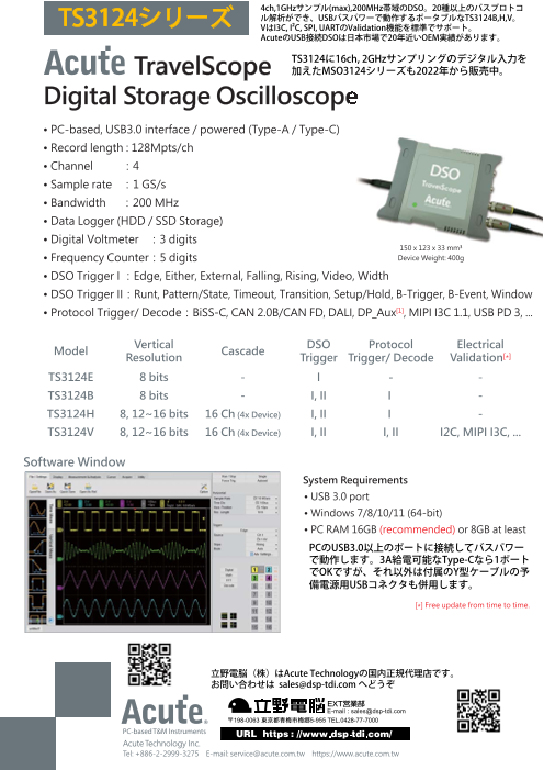
TS3124シリーズ 4ch,1GHzサンプル(max),200MHz帯域のDSO。20種以上のバスプロトコ
ル解析ができ、USBバスパワーで動作するポータブルなTS3124B,H,V。
VはI3C, I²C, SPI, UARTのValidation機能を標準でサポート。
AcuteのUSB接続DSOは日本市場で20年近いOEM実績があります。
TravelScope TS3124に16ch, 2GHzサンプリングのデジタル入力を
加えたMSO3124シリーズも2022年から販売中。
Digital Storage Oscilloscope
• PC-based, USB3.0 interface / powered (Type-A / Type-C)
• Record length : 128Mpts/ch
• Channel :4
• Sample rate :1 GS/s
• Bandwidth :200 MHz
• Data Logger (HDD / SSD Storage)
• Digital Voltmeter :3 digits
150 x 123 x 33 mm³
• Frequency Counter:5 digits Device Weight: 400g
• DSO Trigger I :Edge, Either, External, Falling, Rising, Video, Width
• DSO Trigger II:Runt, Pattern/State, Timeout, Transition, Setup/Hold, B-Trigger, B-Event, Window
• Protocol Trigger/ Decode:BiSS-C, CAN 2.0B/CAN FD, DALI, DP_Aux[1], MIPI I3C 1.1, USB PD 3, ...
Model Vertical DSO Electrical
Resolution Cascade Protocol
Trigger Trigger/ Decode Validation[*]
TS3124E 8 bits - I - -
TS3124B 8 bits - I, II I -
TS3124H 8, 12~16 bits 16 Ch (4x Device) I, II I -
TS3124V 8, 12~16 bits 16 Ch (4x Device) I, II I, II I2C, MIPI I3C, ...
Software Window
System Requirements
• USB 3.0 port
• Windows 7/8/10/11 (64-bit)
• PC RAM 16GB (recommended) or 8GB at least
PCのUSB3.0以上のポートに接続してバスパワー
で動作します。3A給電可能なType-Cなら1ポート
でOKですが、それ以外は付属のY型ケーブルの予
備電源用USBコネクタも併用します。
[*] Free update from time to time.
立野電脳(株)はAcute Technologyの国内正規代理店です。
お問い合わせは sales@dsp-tdi.com へどうぞ
Acute Technology Inc.
Tel: +886-2-2999-3275 E-mail: service@acute.com.tw https://www.acute.com.tw
Page2
TS3000
Model TS3124E TS3124B TS3124H TS3124V
Power source USB bus-power (+5V)
Power Static power consumption 4.5W
Max power consumption 7.7W
Mode Sample, Average, Envelope[*], Peak detect[*], High resolution[*]
@ 1Ch 1 GS/s 1 GS/s︱500 MS/s︱100 MS/s
Sampling @ 2Ch 500 MS/s 500 MS/s︱250 MS/s︱100 MS/s
(8︱12︱≧14 bits)
Acquisition @ 4Ch 250 MS/s 250 MS/s︱125 MS/s︱100 MS/s
@ 1Ch 512 Mpts 512 Mpts︱256 Mpts
Record length @ 2Ch 256 Mpts 256 Mpts︱128 Mpts
(8︱≧12 bits) @ 4Ch 128 Mpts 128 Mpts︱64 Mpts
Input channels 4
Input coupling AC/DC
Input impedance 1 MΩ ∥ <19 pF
Input
Overvoltage protection ± 100 V (DC+AC peak)
Ch-Ch isolation 50dB @DC to 100MHz; 40dB @ 100MHz to 200MHz
Ch-Ch skew 100 ps between two channels with the same scale & coupling settings
Temperature Operating / Storage 5℃~40℃ (41℉~104℉) / -10℃~65℃ (14℉~149℉)
Trig-In Workable:2.5V to 5V / Typical:TTL 3.3V (Rising/Falling)
Trigger pulse approval > 8 ns
Trig-Out TTL 3.3 V
I/O port Ref. Clock input 10MHz, Vpp=3.3 to 5V
Ref. Clock output 10MHz, TTL 3.3V
Connector type MCX jack / female
Bandwidth 200 MHz
Rise time 1.75 ns @ 200 MHz; 3.5 ns @ 100 MHz; 7 ns @ 50 MHz
Resolution 8 bits 8, 12, 14, 15, 16 bits
Vertical Input sensitivity 2 mV/div to 10 V/div (Full-Scale: ±4 div/screen, ±1 div beyond screen)
Offset range ±150 V @ 2, 5, 10 V/div; ±1.5 V @ 0.2, 0.5, 1 V/div; ±1.5 V @ 2, 5, 10, 20, 50, 100 mV/div
DC accuracy ±3% of Full-Scale
Bandwidth limit 20 MHz, 100 MHz or Full
Time scale 1 ns/div to 100 s/div (10 div/screen)
Time resolution 125 ps
Horizontal
Time accuracy ±10 ppm
Delay range Pre-trigger: 0 to 100% of 1 screen; Post-trigger up to 50 sec.
Trigger mode Auto, Normal, Single, Roll*
Source Ch1, Ch2, Ch3, Ch4, Ext. (TTL only)
Coupling DC, LF reject (50kHz), HF reject (50kHz), Noise reject
Trigger range ±4 div from window center
Trigger
Vertical sensitivity 1 div or 5 mV @ <10 mV/div; 0.6 div @ ≧ 10 mV/div
Hold off range ~60 ns to 10 sec.
DSO I Edge, Either, External, Falling, Rising, Video, Width
DSO II --- Runt, Pattern/State, Timeout, Transition, Setup/Hold, B-Trigger, B-Event, Window
BiSS-C, CAN 2.0B/CAN FD, DALI, DP_Aux[1], HID over I2C, I2C, I2S, LIN2.2,
Protocol Trigger / Decode --- MDIO, Mini/Micro LED, MIPI I3C 1.1, MIPI RFFE 3, MIPI SPMI 2, Modbus,
PMBus, ProfiBus, SENT, SMBus, SPI, SVI2, UART, USB PD 3, USB1.1
Measurement Frequency, Period, ±Duty, ±Period, Rise/ Fall Time, Delay, Phase; VMax, VMin, VHigh, VLow, Vpp, VAmp,
VMid, VMean, VRMS, ±Overshoot, Rise/ Fall Preshoot; Edge Count, ±Pulse Count
Cursor Time difference, Voltage difference
Measurement/ Math +, -, x, ÷, XY, lAl, √A, Log(A), Ln(A), ∫Adt, eᴬ
Processing Rectangular, Blackman, Hann, Hamming, Harris, Triangular, Cosine, Lanczos, Gaussian.
FFT
(Vertical Scale: dBm RMS, dbV RMS, Linear RMS)
Export data WORD, EXCEL, CSV, TEXT, HTML, MATLAB
I2C, I2S, MIPI I3C,
Electrical Validation (Protocol)[*] --- MIPI RFFE, MIPI SPMI,
PDM, SPI, UART(RS232)
Max. channels expand --- 16 Ch (4x Device, 1 Master & 3 Slaves)
Cascade Trigger source --- Main device only
Skew between Master & Slave --- ±2ns @ 1 GS/s;±4ns @ 500 MS/s;±8ns @ 250 MS/s
Device (150x123x33 mm³) 1
USB3.0 Y cable (1.8M) 1
Type-C OTG Adapter 1
Packing List 250 MHz Probe 4
Stack cable (30cm) 2
Handbag 1
Total Weight 1200g
[1] Optional DP_Aux adapter needed.
[*] Free update from time to time.
Acute Technology Inc. Tel: +886-2-2999-3275 E-mail: service@acute.com.tw https://www.acute.com.tw 2023.09
© 2023 All right reserved. Acute Technology Inc. Acute and Acute logo is a registered trademark of Acute Technology Inc.
Page3
Functions:
Multiple Devices Stack Mode:
Support DSO stack mode, up to 4 devices
(16 channels) can be stacked together in the
same time.
• Runt Trigger:Use 2 voltage thresholds and pulse width to trigger on either/ ±runt signals.
• Timeout Trigger:Trigger when no pulse is detected within a specified time, range from 2ns to 50s.
• Pulse Width Trigger:Pulse width range from 8ns to 50s.
Positive Runt Negative Runt Width Timeout
• Vertical Offset & Zone View
Voltage division from 2mV/Div - 10V/Div combined with the channel independent Vertical Offset
settings, which can be used for glitch measurement and analysis on DC power, and observing the
ripple and overshooting voltage on DC offseted voltage. It is also possible to use 16Bit high verti-
cal resolution mode (TS3124H/V) with the Zone View feature to observe the DC voltage and ripple
signal together in the same time.
• Spectrum analysis (Fast Fourier transform, FFT)
Apply FFT to the selected channel.
• Multiple Windows
Multiple Window feature provides 4 display
types (1x1, 2x1, 1x2, 2x2), which could displays
16 channels in maximum 4 different windows,
provides clear waveform readability without
lower the vertical resolution.
Page4
• Measurement:
More than 20 types of waveform measurements with
customized threshold settings features, provides
real-time update for vertical, time and channel to
channel timing measurements with statistic features.
Time: Frequency, Period, ±Duty, ±Period,
Rise/Fall Time, Delay, Phase
Vertical: VMax, VMin, VHigh, VLow, Vpp, VAmp,
VMid, VMean, VRMS, ±Overshoot,
Rise/Fall Preshoot
Counter: Edge Count, ±Pulse Count
Math: Add, Subtract, Multiple, Divide, XY, Absolute,
Square Root, LogA, LnA, Exponential, Integral
• Protocol Decode & Trigger Function
Provides, CAN/CAN-FD, I²C, LIN, MIPI I3C 1.1, ProfiBus, SPI, UART(RS232), USB1.1,… protocol decode
and trigger function, which is able to trigger and decode on the specified Command/Address/Data...
Decode the I²C waveforms Decode the differential CAN signals with a differential probe.
(CH1: Differential Probe, CH2: CAN H, CH3: CAN L)
※ Supports CAN-FD, CAN2.0
• Digital Voltmeter (DVM) & Frequency Counter
Provides voltage root-mean-square, voltage average and frequency counter function for the selected channel.
Measure 1 KHz, 2.5 Vpp square waveforms by the Measure 1 KHz, 2.5 Vpp square waveforms
measurement function. by the DVM function.
Packing List
Device USB3.0 Y cable (1.8M) 250 MHz Probe Stack cable Handbag
Type-C OTG Adapter (4 set)