


金メッキFFCに新グランド接続方式のシールド構造を付加し、EMC対策、ウィスカ対策を両立させたフラットケーブルです。同一接点、逆接点タイプ共に対応可能となります。
LBGバンカードは任意のFFC導体をグランド処理可能 FFC導体をグランド処理可能にした構造のFFCです。
従来タイプでは対応の出来なかった逆接点、端末導体金メッキ処理にも対応も実現可能になりました。
グランド処理部は絶縁被覆をレーザー加工にて部分的に剥がし、導体とシールド間の導電処理を行っております。
【用途】
産業機器、車両、通信からPCの民生市場と幅広く、電子機器用配線等のノイズ対策を必要とする製品の機内配線用としてお使いいただけます。
【種類】
導体露出同一面:K1 タイプ
導体露出反対面:L1 タイプ
詳細はカタログをダウンロードしてご確認ください。
このカタログについて
| ドキュメント名 | 基板やコネクタを変えずにノイズ対策!金メッキシールドFFC 「シールドバンカード」 |
|---|---|
| ドキュメント種別 | 製品カタログ |
| ファイルサイズ | 869.6Kb |
| 登録カテゴリ | |
| 取り扱い企業 | 坂東電線株式会社 (この企業の取り扱いカタログ一覧) |
この企業の関連カタログ


このカタログの内容
Page1
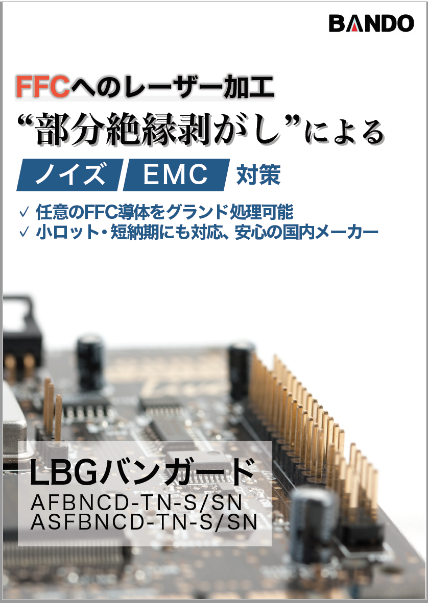
FFCへのレーザー加工
“部分絶縁剥がし”による
ノイズ EMC 対策
✓任意のFFC導体をグランド処理可能
✓小ロット・短納期にも対応、安心の国内メーカー
LBGバンガード
AFBNCD-TN-S/SN
ASFBNCD-TN-S/SN
v.1.60
Page2
ウィスカー EMC
対策 対策 UL RoHS
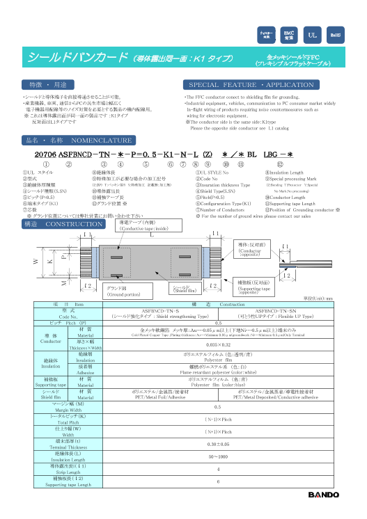
シールドバンカード (導体露出同一面:K1 タイプ) 金メッキシールドFFC
(フレキシブルフラットケーブル)
特徴 ・ 用途 SPECIAL FEATURE ・ APPLICATION
・シールドと導体端子を直接導通させることが可能。 ・The FFC conducter conect to shielding film for grounding.
・産業機器、車両、通信からPCの民生市場と幅広く ・Industrial equipment, vehicles, communication to PC consumer market widely
電子機器用配線等のノイズ対策を必要とする製品の機内配線用。 In-flight wiring of products requiring noise countermeasures such as
※ これは導体露出面が同一面の製品です :K1タイプ wiring for electronic equipment.
反対面はL1タイプです ※The conductor side is the same side:K1type
Please the opposite side conductor see L1 catalog
品名 ・ 名称 NOMENCLATURE
20706 ASFBNCD-TN-*-P=0.5-K1-N-L (Z) * /* BL LBG -*
① ② ③ ④ ⑤ ⑥ ⑦ ⑧ ⑨ ⑩ ⑪ ⑫
①UL スタイル ⑧絶縁体長 ①UL STYLE No ⑧Insulation Length
②型式 ⑨特殊加工が必要な場合の加工記号 ②Code No ⑨Special processing Mark
③絶縁体厚種類 (Z:折り T:パッキン貼り Y:特殊加工 記載無:加工無) ③Insuration thickness Type (Z:Bending T:Protector Y:Special
④シールド種類(S.SN) ⑩導体露出長 ④Shield Type(S.SN) No Mark:No processing)
⑤ピッチ(P=0.5) ⑪補強テープ長 ⑤Pitch(P=0.5) ⑩Conductor Length
⑥端末タイプ(K1) ⑫グランド位置 ※ ⑥Configuraration Type(K1) ⑪Supporting tape Length
⑦芯数 ⑦Number of Conductors ⑫Position of Grounding conductor ※
※ グランド位置については弊社営業にお問い合わせ下さい ※ For the number of ground wires please contact our sales
構造 CONSTRUCTION 導電テープ(内側)
(Conductive tape:inside)
l 1 L l 1
導体:反対面) l 1
(Conductor
:opposite)
l 2
補強板(反対面)
l 2 グランド部 シールド l 2(Shield film) (Supporting tape
(Ground portion) :opposite)
単位(Unit):mm
項 目 Item 構 造 Constraction
型 式 ASFBNCD-TN-S ASFBNCD-TN-SN
Code No. (シールド強化タイプ : Shield strengthening Type) (可とう性UPタイプ : Flexible UP Type)
ピッチ Pitch (P) 0.5
材 質 金メッキ軟銅箔 メッキ厚:Au・・・0.05μm以上(下地Ni・・・0.5μm以上)端末のみ
導 体 Material Gold Plated Copper Tape ,Plating thickness:Au・・・Minimum 0.05μm(groundwork:Ni・・・Minimum 0.5μm)Only Terminal
Conductor 厚さ×幅
0.035×0.32
Thickness×Width
絶縁層 ポリエステルフィルム (色:透明/青)
絶縁体 Insulation Polyester film
Insulation 接着層 難燃ポリエステル系 (色:白)
Adhesive Flame retardant polyester (color:white)
補強板 材 質 ポリエステルフィルム (色:青)
Supporting tape Material Polyester film (color:blue)
シールド 材 質 ポリエステル/金属箔/接着材 ポリエステル/金属蒸着/導電性接着材
Shield film Material PET/Metal Foil/Adhesive PET/Metal Deposited/Conductive adhesive
マージン幅 (M)
0.5
Margin Width
トータルピッチ(K)
( N-1)×Pitch
Total Pitch
仕上り幅(W)
( N+1)×Pitch
Width
端末部厚(t)
0.30±0.05
Terminal Thickness
絶縁体長(L)
50~1000
Insulation Length
導体露出長l(l1)
4
Strip Length
補強板長(l2)
6
Supporting tape Length
W
K
M P
Page3
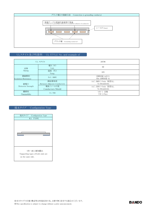
グランド線との接続方法 Connection to grounding conductor
導電テープの導電性接着剤で導通
(Connected to grounding conductor by conductive adhesive of conductive
シールド(Shield
グランド線 (Grounding conductor)
ULスタイル及び性能例 UL STYLE No. and example of
UL スタイル 20706
電圧 (V)
60
定格 Volt.
Rating 温度 (℃)
105
Temp.
絶縁抵抗 1000MΩ-m以上
D.C. 500V
Insulation Resistance Min 1000MΩ-m
隣接導体間 A.C. 500V×1min 異常なし
耐電圧 Between Adjacent Cunductors No Breakdown
Dielectric Strength 導体/シールド間 A.C. 250V×1min 異常なし
Cunductors/Shield No Breakdown
難燃性 VW-1 合格
UL 758
Flammability VW-1 Pass
端末タイプ Configuration Type
端末タイプ Configuration Type
K1 TYPE
・同一面に導体露出
・Supporting tapes of both ends are
on the same side.
※本カタログの仕様・構成等は性能改善の為、お断り無く変更する場合がございます。
※This specification is subject to change without a prior announcement.
Page4
ウィスカー EMC UL RoHS対策 対策
シールドバンカード (導体露出反対面:L1 タイプ) 金メッキシールドFFC
(フレキシブルフラットケーブル)
特徴 ・ 用途 SPECIAL FEATURE ・ APPLICATION
・ノイズ対策としてノーマルFFCにシールドを付加。 ・Add shield to normal FFC as noise countermeasure
・産業機器、車両、通信からPCの民生市場と幅広く ・Industrial equipment, vehicles, communication to PC consumer market widely
電子機器用配線等のノイズ対策を必要とする製品の機内配線用。 In-flight wiring of products requiring noise countermeasures such as
※ これは導体露出面が反対 面の製品です :L1タイプ wiring for electronic equipment.
同一面はK1タイプです ※ The conductor side is opposite side : L1 type
Please the same side conductor see K1 catalog
品名 ・ 名称 NOMENCLATURE
20706 AFBNCD-TN-*-P=0.5-L1-N-L (Z) * /* BL LBG -*
① ② ③ ④ ⑤ ⑥ ⑦ ⑧ ⑨ ⑩ ⑪ ⑫
①UL スタイル ⑧絶縁体長 ①UL STYLE No ⑧Insulation Length
②型式 ⑨特殊加工が必要な場合の加工記号 ②Code No ⑨Special processing Mark
③絶縁体厚種類 (Z:折り T:パッキン貼り Y:特殊加工 記載無:加工無) ③Insuration thickness Type (Z:Bending T:Protector Y:Special
④シールド種類(S.SN) ⑩導体露出長 ④Shield Type(S.SN) No Mark:No processing)
⑤ピッチ(P=0.5) ⑪補強テープ長 ⑤Pitch(P=0.5) ⑩Conductor Length
⑥端末タイプ(L1) ⑫グランド位置 ※ ⑥Configuraration Type(L1) ⑪Supporting tape Length
⑦芯数 ⑦Number of Conductors ⑫Position of Grounding conductor ※
※ グランド位置については弊社営業にお問い合わせ下さい ※ For the number of ground wires please contact our sales
構造 CONSTRUCTION 導電テープ(内側)
(Conductive tape:inside)
l 1 L l 1
導体:反対面)
l 1
(Conductor
:opposite)
l 2
l 2 l 2 補強板(反対面)
グランド部 シールド (Supporting tape
(Shield film)
(Ground portion) :opposite)
単位(Unit):mm
項 目 Item 構 造 Constraction
型 式 AFBNCD-TN-S AFBNCD-TN-SN
Code No. (シールド強化タイプ : Shield strengthening Type) (可とう性UPタイプ : Flexible UP Type)
ピッチ Pitch (P) 0.5
材 質 金メッキ軟銅箔 メッキ厚:Au・・・0.05μm以上(下地Ni・・・0.5μm以上)端末のみ
導 体 Material Gold Plated Copper Tape ,Plating thickness:Au・・・Minimum 0.05μm(groundwork:Ni・・・Minimum 0.5μm)Only Terminal
Conductor 厚さ×幅
0.050×0.32
Thickness×Width
絶縁層 ポリエステルフィルム (色:青)
絶縁体 Insulation Polyester film
Insulation 接着層 難燃ポリエステル系 (色:白)
Adhesive Flame retardant polyester (color:white)
補強板 材 質 ポリエステルフィルム (色:青)
Supporting tape Material Polyester film (color:blue)
シールド 材 質 ポリエステル/金属箔/接着材 ポリエステル/金属蒸着/導電性接着材
Shield film Material PET/Metal Foil/Adhesive PET/Metal Deposited/Conductive adhesive
マージン幅 (M)
0.5
Margin Width
トータルピッチ(K)
( N-1)×Pitch
Total Pitch
仕上り幅(W)
( N+1)×Pitch
Width
端末部厚(t)
0.30±0.05
Terminal Thickness
絶縁体長(L)
50~500
Insulation Length
導体露出長l(l1)
4
Strip Length
補強板長(l2)
6
Supporting tape Length
W
K
M P
Page5
グランド線との接続方法 Connection to grounding conductor
導電テープの導電性接着剤で導通
(Connected to grounding conductor by conductive adhesive of conductive
シールド(Shield
グランド線 (Grounding conductor)
ULスタイル及び性能例 UL STYLE No. and example of
UL スタイル 20706
電圧 (V)
60
定格 Volt.
Rating 温度 (℃)
105
Temp.
絶縁抵抗 1000MΩ-m以上
D.C. 500V
Insulation Resistance Min 1000MΩ-m
隣接導体間 A.C. 500V×1min 異常なし
耐電圧 Between Adjacent Cunductors No Breakdown
Dielectric Strength 導体/シールド間 A.C. 250V×1min 異常なし
Cunductors/Shield No Breakdown
難燃性 VW-1 合格
UL 758
Flammability VW-1 Pass
端末タイプ Configuration Type
端末タイプ Configuration Type
L1 TYPE
・裏表互い違いに補強板
・Supporting tapes of both ends are
on the opposite side.
※本カタログの仕様・構成等は性能改善の為、お断り無く変更する場合がございます。
※This specification is subject to change without a prior announcement.