


このカタログについて
| ドキュメント名 | CPS mini chain |
|---|---|
| ドキュメント種別 | 製品カタログ |
| ファイルサイズ | 108.2Mb |
| 取り扱い企業 | 株式会社サンリツコーポレーション (この企業の取り扱いカタログ一覧) |
この企業の関連カタログ


このカタログの内容
Page1
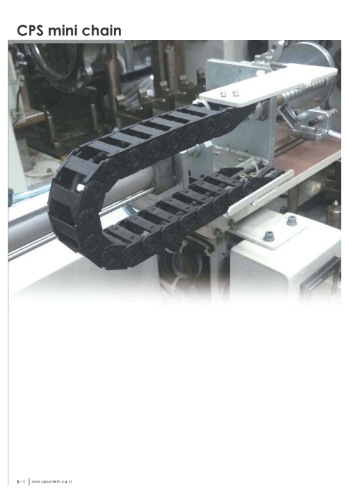
CPS mini chain
B-1 www.cp system .co .kr
Page2
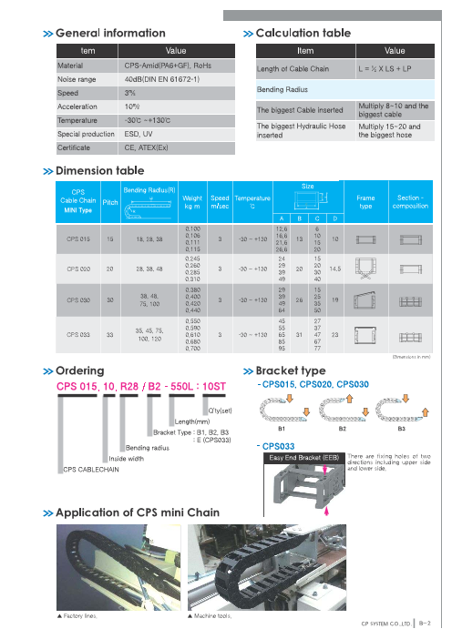
General information Calculation table
Item Value Item Value
Material CPS-Amid(PA6+GF), RoHs Length of Cable Chain L = ½ X LS + LP
Noise range 40dB(DIN EN 61672-1)
Speed 3㎧ Bending Radius
Acceleration 10㎨ Multiply 8~ 10 and theThe biggest Cable inserted
biggest cable
Temperature -30℃ ~ +130℃
The biggest Hydraulic Hose Multiply 15~ 20 and
Special production ESD, UV inserted the biggest hose
Certificate CE, ATEX(Ex)
Dimension table
Size
CPS Bending RadIus(R)
Cable Chain P itc h Weight Speed Temperature Frame Section -
M IN I T yp e kg/m m/sec ℃ type composition
A B C D
0.100 12.6 6
0.106 16.6 10
CPS 015 15 18, 28, 38 3 -30 〜+130 13 10
0.111 21.6 15
0.115 26.6 20
0.245 24 15
0.260 29 20
CPS 020 20 28, 38, 48 3 -30 〜+130 20 14.5
0.285 39 30
0.310 49 40
0.380 29 15
38, 48, 0.400 39 25
CPS 030 30 3 -30 〜+130 26 19
75, 100 0.420 49 35
0.440 64 50
0.550 45 27
35, 45, 75, 0.590 55 37
CPS 033 33 0.610 3 -30 〜+130 65 31 47 23
100, 120 0.680 85 67
0.700 95 77
(Dimensions in mm)
Ordering Bracket type
C P S 0 1 5 . 1 0 . R 2 8 / B 2 - 5 5 0 L : 1 0 S T - C P S 0 1 5 , C P S 0 2 0 , C P S 0 3 0
Q’ty(set)
Length(mm)
B 1 B 2 B 3
Bracket Type : B1, B2, B3
: E (CPS033)
Bending radius - C P S 0 3 3
Inside width Easy End Bracket (EEB) There are fixing holes of two
directions including upper side
CPS CABLECHAIN and lower side.
Application of CPS mini Chain
▲ Factory lines. ▲ Machine tools.
CP SYSTEM CO.,LTD. B-2
Page3
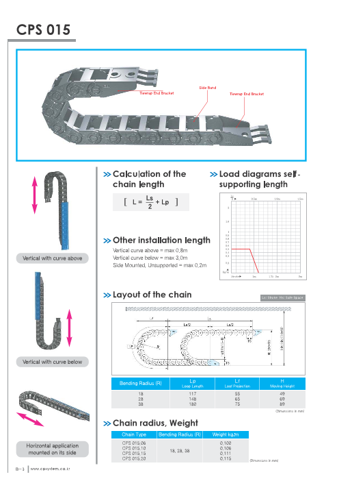
C PS 0 15
S id e B a n d
T ie w ra p E n d B ra c k e t T ie w ra p E n d B ra c k e t
C a lc u la tio n o f th e Lo a d d ia g ra m s se lf-
c h a in le n g th su p p o rtin g le n g th
L = L s2 + L p
O th e r in sta lla tio n le n g th
Vertical curve above = max 0.8m
Vertical with curve above Vertical curve below = max 3.0m
Side Mounted, Unsupported = max 0.2m
La y o u t o f th e c h a in Ls: Stroke Hs: Safe Space
Vertical with curve below
Bending Radius (R) Lp Lf H
Loop Length Loof Projection Moving Height
18 117 55 49
28 148 65 69
38 180 75 89
(Dimensions in mm)
C h a in ra d iu s , W e ig h t
Chain Type Bending Radius (R) Weight kg/m
CPS 015.06 0.100
Horizontal application CPS 015.10 0.106
mounted on its side 18, 28, 38CPS 015.15 0.111
CPS 015.20 0.115
(Dimensions in mm)
B-3 www.cp system .co .kr
Page4
C h a in c ro ss se c tio n
(Dimensions in mm)
CPS015.06 CPS015.10 CPS015.15 CPS015.20
End bracket (Tie wrap type)
(Dimensions in mm)
CPS015.06 Moving point CPS015.06 Fixing point
CPS015.10 Moving point CPS015.10 Fixing point
CPS015.15 Moving point CPS015.15 Fixing point
CPS015.20 Moving point CPS015.20 Fixing point
CP SYSTEM CO.,LTD. B-4
Page5
C PS 0 20
B o th S id e s , S id e B a nd
H ing e F ra m e
T ie w ra p E n d B ra c k e t T ie w ra p E nd B ra c k e t
C a lc u la tio n o f th e Lo a d d ia g ra m s se lf-
c h a in le n g th su p p o rtin g le n g th
L = L 2
s + L p
O th e r in sta lla tio n le n g th
Vertical curve above = max 1.0m
Vertical with curve above Vertical curve below = max 5.0m
Side Mounted, Unsupported = max 0.5m
La y o u t o f th e c h a in Ls: Stroke Hs: Safe Space
Vertical with curve below
Bending Radius (R) Lp Lf H
Loop Length Loof Projection Moving Height
28 170 78 76
38 200 88 96
48 230 98 116
(Dimensions in mm)
C h a in ra d iu s , W e ig h t
Chain Type Bending Radius (R) Weight kg/m
CPS 020.15 0.245
Horizontal application CPS 020.20 0.260
mounted on its side 28, 38, 48CPS 020.30 0.285
CPS 020.40 0.310
(Dimensions in mm)
B-5 www.cp system .co .kr
Page6
C h a in c ro ss se c tio n
(Dimensions in mm)
CPS020.15 CPS020.20 CPS020.30 CPS020.40
En d b ra c k e t ( Tie w ra p ty p e )
(Dimensions in mm)
CPS020.15 Moving point CPS020.15 Fixing point
CPS020.20 Moving point CPS020.20 Fixing point
CPS020.30 Moving point CPS020.30 Fixing point
4
CPS020.40 Moving point CPS020.40 Fixing point
CP SYSTEM CO.,LTD. B-6
Page7
CPS 030
T ie w ra p E n d B ra c k e t
T ie w ra p E nd B ra c k e t S id e B a n d
F ra m e
O ne P ie c e S k ie
Calculation of the Load diagrams self-
chain length supporting length
L = L s2 + L p
Other installation length
Vertical curve above = max 1.5m
Vertical with curve above Vertical curve below = max 10.0m
Side Mounted, Unsupported = max 0.6m
Layout of the chain Ls: Stroke Hs: Safe Space
Vertical with curve below
Bending Radius (R) Lp Lf H
Loop Length Loof Projection Moving Height
38 240 110 101
48 271 119 121
75 356 148 175
100 434 173 225
(Dimensions in mm)
Chain radius, Weight
Chain Type Bending Radius (R) Weight kg/m
CPS 030.15 0.38
Horizontal application CPS 030.25 0.40
mounted on its side 38, 48, 75, 100CPS 030.35 0.42
CPS 030.50 0.44
(Dimensions in mm)
B-7 www.cp system .co .kr
Page8
Chain cross section
(Dimensions in mm)
CPS030.15 CPS030.25 CPS030.35 CPS030.50
3.2
3.2 3.2
End bracket (Tie wrap type)
(Dimensions in mm)
CPS030.15 Moving point CPS030.15 Fixing point
CPS030.25 Moving point CPS030.25 Fixing point
4 4
CPS030.35 Moving point CPS030.35 Fixing point
4 4
CPS030.50 Moving point CPS030.50 Fixing point
4
CP SYSTEM CO.,LTD. B-8
Page9
CPS 033
S id e B a n d
F ra m e
T ie W ra p
O n e P ie c e S k id
F re e E nd B ra c k e t
F re e E n d B ra c k e t
Calculation of the Load diagrams self-
chain length supporting length
L = L s2 + L p
Other installation length
Vertical curve above = max 1.5m
Vertical with curve above Vertical curve below = max 10.0m
Side Mounted, Unsupported = max 0.6m
Layout of the chain Ls: Stroke Hs: Safe Space
Vertical with curve below
Bending Radius (R) Lp Lf H
Loop Length Loof Projection Moving Height
35 242 117 101
45 274 127 121
75 368 157 181
100 446 182 231
120 509 202 271
(Dimensions in mm)
Horizontal application
mounted on its side
B-9 www.cp system .co .kr
Page10
Chain cross section
(Dimensions in mm)
CPS033.27 CPS033.37 CPS033.47
3.2 3.2
CPS033.67 CPS033.77
3.2 3.2
Easy end bracket Tie wrap (TW)
Moving point Fixing point Tie wrap prevents cut off
problem of the cable by
2-Ø5(M4 Bolt Holes) 2-Ø5(M4 Bolt Holes) the twisting and pulling
movement.
The tie wrap of this CPS
CABLE Chain has two
types, separated with
16 Front point bracket type and attached
with bracket type.
A 6.5
B 2.5
7 4
4 C
33.2 33.2 C
49.7 51.7 A 7
Chain Type A B C D Hole Type 16.5 D 16.5 5
Width(Outer) Height(Outer) Frame Height(Inner)
45 27 Chain Type Ordering No. A B C D
55 37 M4
CPS 033 65 31 47 23 Bolt S-TW033/20CR.27 45.0 27.5 10.20 12.0
85 67 Holes S-TW033/20CR.37 55.0 41.0 8.50 22.0
95 77 CPS 033 S-TW033/20CR.47 65.0 48.0 10.40 32.0
(Dimensions in mm) S-TW033/20CR.67 85.0 68.0 10.00 52.0
S-TW033/20CR.77 95.0 78.0 8.87 62.0
(Dimensions in mm)
Easy end bracket (Tie wrap type)
Moving point Fixing point
10 2-Ø5(M4 Bolt Holes) 2-Ø5(M4 Bolt Holes)10
18 16 16 18 Front point
C
33.2 33.2 A
15 49.7 51.7 15 3
Chain Type A B C D E Hole Type
Width(Outer) Height(Outer) Frame Height(Inner) Hole width
45 27 12
55 37 22 M4
CPS 033 65 31 47 23 32 Bolt
85 67 52 Holes
95 77 62
(Dimensions in mm)
CP SYSTEM CO.,LTD. B-10
A
A-8
7 A
31 4 31 A-8
2.5 21 C
E
C
2.5 4 21
31 7 A-831
A-8 A
A
D D
B B
25 18
10 6
5
25 15 3
43
E
Page11
Shift Chain
ST - N : ST - E : ST - S :
Normal type Enclosed type Skid type
▶ST044N C-9 ▶ST044E C-27 ▶ST044 S C-43
▶ST055 N C-11 ▶ST055E C-29
▶ST072N C-13 ▶ST072E C-31
▶ST095N C-15 ▶ST095E C-33
▶ST120N C-17 ▶ST120E C-35
▶ST150N C-19 ▶ST150E C-37
C-1 www.cpsystem.co.kr
Page12
ST - ES : ST - RS : ST - ERS :
Enclosed Skid type Roller Skid type Enclosed Roller Skid type
▶ST044E S C-51 ▶ST044R S C-65 ▶ST044 ERS C-81
▶ST072ES C-53 ▶ST072RS C-67 ▶ST072ERS C-83
▶ST095ES C-55 ▶ST095RS C-69 ▶ST095ERS C-85
▶ST120ES C-57 ▶ST120RS C-71 ▶ST120ERS C-87
▶ST150RS C-73
CP SYSTEM CO.,LTD. C-2
Page13
Shift Chain - Normal type
General information Calculation table
Item Value Item Value
Material CPS-Amid(PA6+GF), RoHs Length of Cable Chain L = ½ X LS + LP
Speed 3㎧
Acceleration 10㎨ Bending Radius
Temperature -30℃ ~+130℃ Multiply 8~10 and theThe biggest Cable inserted
biggest cable
Special production ESD, UV
The biggest Hydraulic Hose Multiply 15~20 and
Certificate CE, ATEX(Ex) inserted the biggest hose
Dimension table
Bending RadIus Size Ordering
(R) Section-Shift Chain Weight Speed Temperature Frame
Pitch composi-
N Type kg/m m/s ℃ type tion ST 044N. 100. R120 / F - 1500L : 10ST
A B C D
0.93 56 35
0.97 71 50 Q’ty(set)
1.00 76 55
50, 70, 90, 1.06 -30 ~ 96 75
ST 044N 44 1.17 3 121 38 100 26 Length(mm)
120, 150 1.30 +130 146 125
1.43 171 150 Bracket Type
1.78 196 175
1.94 221 200 F : Free End Bracket
1.12 56 35 FT : Tie Wrap
1.15 71 50 FST : System Tie Wrap
1.18 76 55
65, 75, 1.23 96 75 B1, B2 and B3 : ST150N-30 ~
ST 055N 55 100, 125, 1.31 3 121 52 100 40
1.41 +130150, 200 146 125 Bending radius
1.51 171 150
1.78 196 175 Inside width
1.92 221 200
2.10 82 50 Normal type (N)
2.20 107 75
2.30 132 100 Shift Chain
2.43 157 125
72, 100, 2.51 172 140
120, 145, 2.56 -30 ~ 182 150
ST 072N 72 2.62 3 197 66 165 45
200, 250, 2.66 +130 207 175
300 2.93 222 190
3.11 232 200 Bracket type
3.21 272 240
3.24 282 250
3.60 332 300 - ST044, ST055, ST072, ST095, ST120
3.11 113 75
3.17 138 100 Fixing End Bracket (FEB)
3.37 163 125
3.49 188 150
135, 150, 3.60 213 175
-30 ~
ST 095N 95 200, 230, 3.71 3 2283.79 238 82
190
+130 200
56
280, 400 4.00 278 240
4.05 288 250
4.31 338 300
4.69 388 350
5.05 438 400
4.41 117 75 ST 044N, 055N ST 072N, 095N, 120N
4.53 142 100
4.61 157 115
4.67 167 125
4.78 192 150 - ST150
4.93 217 175
180, 200, 5.17 242 200 Steel End Bracket (SEB)
250, 300, 5.41 -30 ~ 282 240
ST 120N 120 5.47 3 292 108 250 78
350, 400, 5.80 +130 332 290
500 5.88 342 300
6.30 392 350
6.73 442 400
7.07 492 450
7.30 542 500
8.13 592 550
8.30 642 600
5.85 121 75
5.96 146 100 ST 150N
6.03 161 115
6.08 171 125
6.18 196 150 For ST150N, its end parts of cable chain being fixed are used with steel
6.30 221 175 bracket, and it is possible to be installed B1, B2, B3 types of brackets.
6.51 246 200
205, 305, 6.72 -30 ~ 286 240
ST 150N 150 405, 505, 6.78 3 296 140 250 110
605 7.06
+130 336 290
7.14 346 300
7.51 396 350
7.88 446 400
8.18 496 450 B1 B2 B3
8.37 546 500
9.11 596 550
9.26 646 600
(Dimensions in mm)
C-3 www.cpsystem.co.kr
Page14
Application of Shift Chain
- Shift Chain can be applied to all kinds of machine tools and factory lines.
▶ ST 044N Application: ▶ ST 120N Application:
Machine tool Robot Carriage line
Location: Location:
Italy China
Remark: Remark:
Verious stroke and direction Stroke 3 meters
▶ ST 095N
Application:
Steel manufacturing line
Location:
Korea
Remark:
Verious stroke and direction
▶ ST 072N
Application:
Nylon Cloth cutting machine
▶ ST 055N Application: Location:
Machine tool Italy
Location: Remark:
Japan Stroke 2.5 meters
Remark:
Side mounting
Customized Shift Chain
Shift Chain is designed to be able to move in upper, lower and diagonal
directions according to machine's movement.
Changing a different Bending Radius value at the point that the chain
movement turn other sides can create the bending radius or the reverse
bending radius for the direction that you need, so the machine can move
in zigzag direction.
Shift Chain can be used for special usage such as a zigzag chain, and
has an excellent installation scalability in any hazard environment for cable
protection with the general chain. If you need special chain installation,
please contact our R&D center.
CP SYSTEM CO.,LTD. C-4
Page15
Shift Chain - Normal type
Part of Shift Chain Normal type
5
4 3
7
2
8
1
6
9
❶ Side Band (SB) ❻ Frame Pin (FP)
A unit that connects each side band and between them BR is The connecting pin for preventing the breakaway of Frame
inserted to strengthen clamping force. connected at Side Band, combining and fixing the Frame and Side
Band. For Shift chain(ST)072N, 092N, 120N, 150N type, one side
of the frame is fixed by inserting a fixing pin to prevent frame open,
❷ Bending Radius Unit (BR) which caused by any external impact. Also, in case of ST044N,
ST055N type, an open side of the frame is fixed by Hook-type frame.
A unit that inserted between each side band.
There are 6 supporting points to create durability.
❼ Free End Bracket (FEB)
❸ Divider (DV-S, M, R, T) A unit that connects at last side band (left&right).
It can be fixed stronger using steel washers.
A unit that divides inserted cables horizontally.
❽ Tie Wrap (TW)
❹ Separator (SP)
A unit that ties cables to maintain straightness of them.
A unit that divides inserted cables vertically to prevent twisting and It can be assembled to bracket directly or installed separately from
breaking problem. bracket.
❺ Frame (Hinged Type) (FR) ❾ System Tie Wrap (STW)
Hinged-type frame, open one side, supports connection of both side System-Tie Wrap has to be assembled on fixing and moving point
of side band and have tongue and groove system plate to secure of bracket and can be assembled wthout any tie wrap plate. This tie
the position of the divider on the frame. wrap is used to stay the cables on several floors prevent the cables
from being twisted and it can also be assemble without any tools or
bolt. This tie wrap has two types, one is to assemble inside bracket
the other one is outside.
C-5 www.cpsystem.co.kr
Page16
Assembly procedure of Shift Chain Normal type
The assembling process of Shift Chain N-Type is like below and users must use rubber hammer with careful
combination of Divider and Separator. Be careful of different assembling process depending on product specification
such as ST044N, 055N Type, ST072N, 095N, 120N Type, ST150N Type etc.
1 Insert BR unit to each side band, connect the side bands as Fix the separator and divider patterns to the bottom-sidemany as you need, then do the same process to the other side 5 frames as needed.of side band.
2 Assemble the end brackets on For ST150N, assemble 6 Attach frames to one side groove ST044N, 055N frameboth ends using the same steel brackets on both on the side band, type.method. ends. and then the other side.
3 Attach frames to one side groove ST 044N, 055N are 7 Insert frame pins to secure the frames and complete carrier.on the side band, Hinge Type or Hook (ST072N, 095N, 120N, 150N are applied with frame pin, andand then the other side. Type without frame pin. ST044N, 055N are Hinge Type or Hook Type without frame pin.)
4 For ST072N, 095N,120N, and 150N, connect the pin of separatorin hole of divider after inserting separator in hole of divider. For Assembled Shift Chain N-Type is assembled.ST044N and ST055N, separator fixing pins are not used. 8
CP SYSTEM CO.,LTD. C-6
Page17
Shift Chain - Normal type
Part list of Shift Chain Normal type
● Composition of Cable chain(Standard)
= Side band(RH) + Frame + Side band(LH) + Bending radius Unit + Free end bracket
● M divider(normal divider) should be applied every second frames to make a section composition.
※ Please refer to below part list and description to understand composition of cable chain.
Model Classification Part number Description
SIDE BAND ST ‐SB044N/E(LH) Left side band of ST044NST-S B044N/E(RH) Right side band of ST044N
BENDING RADIUS ST-B R044.R50,70,90,120,150 Bending radius unit for side band
sb-FR/M.35 Frame, 35mm
sb-FR/M.50 Frame, 50mm
sb-FR/M.55 Frame, 55mm
sb-FR/M.75 Frame, 75mm
FRAME sb-FR/M.100 Frame, 100mm
sb-FR/M.125 Frame, 125mm
sb-FR/M.150 Frame, 150mm
sb-FR/M.175 Frame, 175mm
sb-FR/M.200 Frame, 200mm
FREE END BRACKET ST-FEB044N/S End bracket of ST044N
DIVIDER sb-D V028/M Normal dividersb-D V028/S To fix separstors at the both side section
ST044N
S-S P/M.35 Separator, 35mm
S-S P/M.50 Separator, 50mm
S-S P/M.75 Separator, 75mm
S-S P/M.100 Separator, 100mm
SEPARATOR
S-S P/M.125 Separator, 125mm
S-S P/M.150 Separator, 150mm
S-S P/M.175 Separator, 175mm
S-S P/M.200 Separator, 200mm
S‐ TW036/025CR.35 Tie wrap for end bracket to fix cables, 35mm
S-TW036/025CR.55 Tie wrap for end bracket to fix cables, 55mm
TIE WRAP S-T W036/025CR.75 Tie wrap for end bracket to fix cables, 75mm
S-TW036/025CR.100 Tie wrap for end bracket to fix cables, 100mm
S-T W036/025CR.125 Tie wrap for end bracket to fix cables, 125mm
SYSTEM TIE WRAP sb‐ DV028/W Divider for fixing cables at end bracketS ‐TW.EB028 System tie wrap to arrange for cables right after moving bracket or fixing bracket
Model Classification Part number Description
SIDE BAND ST‐ SB055N/E(LH) Left side band of ST055NST-S B055N/E(RH) Right side band of ST055N
BENDING RADIUS ST ‐BR055.R65,75,100,125,150,200 Bending radius unit for side band
sb-FR/M.35 Frame, 35mm
sb-FR/M.50 Frame, 50mm
sb-FR/M.55 Frame, 55mm
sb-FR/M.75 Frame, 75mm
FRAME sb-FR/M.100 Frame, 100mm
sb-FR/M.125 Frame, 125mm
sb-FR/M.150 Frame, 150mm
sb-FR/M.175 Frame, 175mm
sb-FR/M.200 Frame, 200mm
FREE END BRACKET ST-FEB055N/S End bracket of ST055N
DIVIDER sb-D V035/M Normal dividersb-D V035/S To fix separstors at the both side section
S-S P/M.35 Separator, 35mm
ST055N S-S P/M.50 Separator, 50mm
S-S P/M.55 Separator, 55mm
S-S P/M.75 Separator, 75mm
SEPARATOR S-S P/M.100 Separator, 100mm
S-S P/M.125 Separator, 125mm
S-S P/M.150 Separator, 150mm
S-S P/M.175 Separator, 175mm
S-S P/M.200 Separator, 200mm
S-TW050/035N.50 Tie wrap for end bracket to fix cables, 50mm
S-TW050/035N.75 Tie wrap for end bracket to fix cables, 75mm
S-TW050/035N.100 Tie wrap for end bracket to fix cables, 100mm
TIE WRAP S-TW050/035N.125 Tie wrap for end bracket to fix cables, 125mm
S-TW050/035N.150 Tie wrap for end bracket to fix cables, 150mm
S-TW050/035N.175 Tie wrap for end bracket to fix cables, 175mm
S-TW050/035N.200 Tie wrap for end bracket to fix cables, 200mm
SYSTEM TIE WRAP sb ‐DV035/W Divider for fixing cables at end bracket
S‐ TW.EB035 System tie wrap to arrange for cables right after moving bracket or fixing bracket
Model Classification Part number Description
SIDE BAND ST- SB072N/E(LH) Left side band of ST072NST-SB072N/E(RH) Right side band of ST072N
BENDING RADIUS ST‐ BR055.R65,75,100,125,150,200 Bending radius unit for side band
FRAME PIN S- FP/S1 Frame pin
sb-FR045.50 Frame, 50mm
sb-FR045.75 Frame, 75mm
sb-FR045.100 Frame, 100mm
sb-FR045.125 Frame, 125mm
sb-FR045.140 Frame, 140mm
sb-FR045.150 Frame, 150mm
FRAME sb-FR045.165 Frame, 165mm
sb-FR045.175 Frame, 175mm
sb-FR045.190 Frame, 190mm
sb-FR045.200 Frame, 200mm
sb-FR045.240 Frame, 240mm
sb-FR045.250 Frame, 250mm
ST072N sb-FR045.300 Frame, 300mm
FREE END BRACKET ST-F EB072N/S End bracket of ST072Nsb- FEB/WH045 Steel washer for end bracket
sb- DV045/M Normal divider
DIVIDER sb-D V045/S To fix separstors at the both side section
sb- DV045/T T divider
sb-D V045/TP T divider pin
SEPARATOR sb- SP/400.400 Separator, 400mm
SP‐ PIN045 Separator pin to fix
S-TW50 Tie wrap for end bracket to fix cables, 50mm
S-TW75 Tie wrap for end bracket to fix cables, 75mm
TIE WRAP S-TW100 Tie wrap for end bracket to fix cables, 100mm
S-TW125 Tie wrap for end bracket to fix cables, 125mm
S-TW150 Tie wrap for end bracket to fix cables, 150mm
SYSTEM TIE WRAP sb ‐DV045/W Divider for fixing cables at end bracket
S ‐TW.EB045 System tie wrap to arrange for cables right after moving bracket or fixing bracket
C-7 www.cpsystem.co.kr
Page18
Model Classification Part number Description
ST-S B095N/E(LH) Left side band of ST095N
SIDE BAND
ST-SB095N/E(RH) Right side band of ST095N
BENDING RADIUS ST ‐BR055.R65,75,100,125,150,200 Bending radius unit for side band
FRAME PIN S-FP/S1 Frame Pin
sb-FR060.75 Frame, 75mm
sb-FR060.100 Frame, 100mm
sb-FR060.125 Frame, 125mm
sb-FR060.150 Frame, 150mm
sb-FR060.175 Frame, 175mm
sb-FR060.190 Frame, 190mm
FRAME
sb-FR060.200 Frame, 200mm
sb-FR060.230 Frame, 230mm
sb-FR060.250 Frame, 250mm
sb-FR060.300 Frame, 300mm
sb-FR060.350 Frame, 350mm
ST095N sb-FR060.400 Frame, 400mm
FREE END BRACKET ST-FEB095N/S End bracket of ST095Nsb-FEB/WH060 Steel washer for end bracket
sb-DV060/M Normal divider
sb-DV060/S To fix separstors at the both side section
DIVIDER
sb-DV060/T T divider
sb-DV060/TP T divider pin
sb-SP/400.400
SEPARATOR Separator, 400mm
SP-PIN060 Separator pin to fix
S-TW50 Tie wrap for end bracket to fix cables, 50mm
S-TW75 Tie wrap for end bracket to fix cables, 75mm
TIE WRAP S-TW100 Tie wrap for end bracket to fix cables, 100mm
S-TW125 Tie wrap for end bracket to fix cables, 125mm
S-TW150 Tie wrap for end bracket to fix cables, 150mm
SYSTEM TIE WRAP sb ‐DV060/W Divider for fixing cables at end bracketS ‐TW.EB060 System tie wrap to arrange for cables right after moving bracket or fixing bracket
Model Classification Part number Description
ST-S B120N/E(LH) Left side band of ST120N
SIDE BAND
ST-SB120N/E(RH) Right side band of ST120N
BENDING RADIUS ST-BR120.R180, 200, 250, 300, 350, 400, 500 Bending radius unit for side band
FRAME PIN S-FP/S2 Frame Pin
sb-FR075/100.75 Frame, 75mm
sb-FR075/100.100 Frame, 100mm
sb-FR075/100.115 Frame, 115mm
sb-FR075/100.125 Frame, 125mm
sb-FR075/100.150 Frame, 150mm
sb-FR075/100.175 Frame, 175mm
sb-FR075/100.200 Frame, 200mm
sb-FR075/100.240 Frame, 240mm
FRAME sb-FR075/100.250 Frame, 250mm
sb-FR075/100.290 Frame, 290mm
sb-FR075/100.300 Frame, 300mm
sb-FR075/100.350 Frame, 350mm
sb-FR075/100.400 Frame, 400mm
sb-FR075/100.450 Frame, 450mm
sb-FR075/100.500 Frame, 500mm
ST120N sb-FR075/100.550 Frame, 550mm
sb-FR075/100.600 Frame, 600mm
FREE END BRACKET ST-FEB120N/S End bracket of ST120Nsb-FEB/WH075 Steel washer for end bracket
sb-DV075/M Normal divider
sb-DV075/S To fix separstors at the both side section
DIVIDER
sb-DV075/T T divider
sb-DV075/TP T divider pin
sb-SP/400.400 Separator, 400mm
SEPARATOR
SP-PIN075 Separator pin to fix
S-TW50 Tie wrap for end bracket to fix cables, 50mm
S-TW75 Tie wrap for end bracket to fix cables, 75mm
TIE WRAP S-TW100 Tie wrap for end bracket to fix cables, 100mm
S-TW125 Tie wrap for end bracket to fix cables, 125mm
S-TW150 Tie wrap for end bracket to fix cables, 150mm
SYSTEM TIE WRAP sb ‐DV075/W Divider for fixing cables at end bracketS ‐TW.EB075 System tie wrap to arrange for cables right after moving bracket or fixing bracket
Model Classification Part number Description
ST-S B150N/E(LH) Left side band of ST150N
SIDE BAND
ST-SB150N/E(RH) Right side band of ST150N
BENDING RADIUS ST-BR150.R205,305,405,505,605 Bending radius unit for side band
FRAME PIN S-FP/S2 Frame Pin
sb-FR075/100.75 Frame, 75mm
sb-FR075/100.100 Frame, 100mm
sb-FR075/100.115 Frame, 115mm
sb-FR075/100.125 Frame, 125mm
sb-FR075/100.150 Frame, 150mm
sb-FR075/100.175 Frame, 175mm
sb-FR075/100.200 Frame, 200mm
sb-FR075/100.240 Frame, 240mm
FRAME sb-FR075/100.250 Frame, 250mm
sb-FR075/100.290 Frame, 290mm
sb-FR075/100.300 Frame, 300mm
sb-FR075/100.350 Frame, 350mm
sb-FR075/100.400 Frame, 400mm
ST150N sb-FR075/100.450 Frame, 450mm
sb-FR075/100.500 Frame, 500mm
sb-FR075/100.550 Frame, 550mm
sb-FR075/100.600 Frame, 600mm
STEEL END BRACKET ST-SEB150N/B1~B2~B3 Steel end bracket of ST150N
sb-DV075/M Normal divider
sb-DV075/S To fix separstors at the both side section
DIVIDER
sb-DV075/T T divider
sb-DV075/TP T divider pin
sb-SP/600.600 Separator, 600mm
SEPARATOR
SP-PIN100 Separator pin to fix
S-TW50 Tie wrap for end bracket to fix cables, 50mm
S-TW75 Tie wrap for end bracket to fix cables, 75mm
TIE WRAP S-TW100 Tie wrap for end bracket to fix cables, 100mm
S-TW125 Tie wrap for end bracket to fix cables, 125mm
S-TW150 Tie wrap for end bracket to fix cables, 150mm
CP SYSTEM CO.,LTD. C-8
Page19
ST 044N
▲ Hinge hook type
▲ Shift Chain
Calculation of the Load diagrams self-
chain length supporting length
Ls 1m 2m 2.5m 3m 4m 5m 6m
[ L = + Lp ]
2
Other installation length
Vertical with curve above Vertical curve above = max 2.0m
Vertical curve below = max 40m
Side Mounted, Unsupported = max 1.0m
Kg/m
Stroke 2m 4m 5m 6m 8m 10m 12m
Layout of the chain Ls: Stroke Hs: Safe Space
Lf Ls
Ls/2 Ls/2
Vertical with curve below 44
38
Bending Radius (R) Lp Lf H
Loop Length Loof Projection Moving Height
50 333 157 138
70 396 177 178
90 459 197 218
Horizontal application 120 553 227 278
mounted on its side 150 648 257 338
(Dimensions in mm)
C-9 www.cpsystem.co.kr
H: 2R+38
Hs: Hs H+30
Page20
Chain cross section Dividers(DV)
➌
3.2
➊ ➋
3.2 D B
➍
C ➎
A
Assemble divider every second frame.
DV.T : Applied to Frame 125~200.
A B C D DV.M : Normal Divider. System Tie wrap
Chain Type Weight kg/m DV.W : Tie wrap divider for free end bracket(FEB).
Width (Outer) Height (Outer) Frame Height (Inner)
❶ sb-DV028/S ❷ sb-DV028/M1
56 35 0.93
71 50 0.97
76 55 1.00
3.2
96 75 1.06
9.7 9.7
ST 044N 121 38 100 26 1.17
146 125 1.30
13 13
171 150 1.43 16.6 6.2 16.6 9.6
196 175 1.78
221 200 1.94 ❸ sb-DV028/M2 ❹ sb-DV028/T
(Dimensions in mm)
Free end bracket
4 3.2
9.7
Moving point Fixing point 9.7
13 11.8
9.6 13
6-Ø5.6(M5 Bolt Holes) 6-Ø5.6(M5 Bolt Holes) 16.6 9.616.6
❺ sb-DV028/W
9.3
3.2
1010 1010 Front point 9.7
F 13 18.3
C+14 16.6 9.6
C (Dimensions in mm)
64 64 E
Separators(SP)
4.2 21.8 21.8 4.2 2-Ø5.6(M5 Bolt Holes)
20~200mm
Chain Type F B C D E Hole Type
Width(Outer) Height(Outer) Frame Height(Inner) M.EB Bolt hole width 15mm
60.4 35 0.4
75.4 50 15.4
80.4 55 20.4
100.4 75 40.4 M5 Chain Type Ordering NO. Frame
ST 044N 125.4 38 100 26 65.4 Bolt
150.4 125 90.4 Holes S-SP/M.35 35
175.4 150 115.4 S-SP/M.50 50
200.4 175 140.4 S-SP/M.55 55
225.4 200 165.4 S-SP/M.75 75
ST 044N S-SP/M.100 100
(Dimensions in mm) S-SP/M.125 125
System tie wrap (STW) S-SP/M.150 150S-SP/M.175 175
S-SP/M.200 200
It is a unit to classify each cable for
preventing entanglement of cables.
It can either be installed to free end Tie wrap (TW)
bracket or installed separately according
its application environment.
Front point Upper side point Side point
C+24 Attached to Bracket
C+12
C A
4-Ø6.5(M6 Bolt Holes) 9.7 10 3
6 12 4
59
12
Chain Type Ordering No. C Frame Hole Type C (Dimensions in mm)
S-TW.EB028.35 35 Chain Type Ordering No. A B C
S-TW.EB028.50 50
S-TW.EB028.55 55 S-TW036/025CR.35 46 35.4 -
S-TW.EB028.75 75 S-TW036/025CR.50 69 48.9 15
ST 044N S-TW.EB028.100 100 M6 Bolt Holes
S-TW.EB028.125 125 ST 044N
S-TW036/025CR.55 70 48.9 20
S-TW.EB028.150 150 S-TW036/025CR.75 94 48.9 40
S-TW.EB028.175 175 S-TW036/025CR.100 118 48.9 65
S-TW.EB028.200 200 S-TW036/025CR.125 142 48.9 90
(Dimensions in mm) CP SYSTEM CO.,LTD. C-10
F
38 C+20
C+14
38 C
29 C-20E
47
29 E
38 C-20
C
C+14
C+20
F
38
9.7
2.1
4.9 D
B
33 33
26 26
2.1 2.1
33 4.9
26 4.9
18.9 3 2.1
B
5
8
33
33
26
26
2.1
2.1
4.9
4.9