


精密ボールねじ+Si-servoの採用により、「完全等ピッチ位置決め」「振動レス」「脱調レス」が可能なハイブリッド製品です。
◆掲載内容
・特長
・基本仕様
・モータ仕様
・トルク特性
・ドライバ外形寸法
・ドライバ仕様
・接続
・制御信号
・通信コマンド一覧
・パラメータ一覧表
・ケーブル仕様
・ポイントテーブル
・寸法諸元
このカタログについて
| ドキュメント名 | リニアアクチュエータ(Externalタイプ) 精密ボールねじ+エンコーダ付きステッピングモータ(Si-servo) |
|---|---|
| ドキュメント種別 | 製品カタログ |
| ファイルサイズ | 3.6Mb |
| 登録カテゴリ | |
| 取り扱い企業 | ケーエスエス株式会社 (この企業の取り扱いカタログ一覧) |
この企業の関連カタログ


このカタログの内容
Page1
ハイブリッドタイプ(SiMB)
Hybrid type(SiMB)
Si-ムーボ / Si-MoBo
●特長
•精密ボールねじの軸端にステッピングサーボモータを直付けした、
高分解能、高精度位置決めに優れた製品です。
•モータ後部にエンコーダ及びメモリー素子を搭載し、
完全等ピッチ位置決め、振動レス、脱調レスを実現しました。
•ボールねじ軸心がモータ回転軸心となる理想的な構造です。
•直付け構造により、カップリングが不要で、長手方向寸法の短縮とともに
作業工数の低減が期待できます。
•専用コントローラドライバ、専用ケーブルを用意しています。
•ナットブロックやモータプレートなどの付属品も充実しています。
●Features
•A Stepping Servo Motor, what we call Si-servo Motor, is mounted directly onto the Shaft end of a
Precision Ball Screw, which is high resolution and precise positioning unit.
•An Encoder and a Memory chip are installed at the end of Motor,
high accurate positioning, ultra smooth drive, and closed loop function have been achieved.
•Ball Screw Shaft is ideally constructed to form the Motor Rotor Shaft.
•Since combining the Motor Shaft and Ball Screw Shaft, Coupling-less, saving total length,
and reducing labor cost can be achieved.
•Exclusive Driver, and Cable are provided for Si-servo Motor.
•Accessories are also provided as mounting kit, such as Nut block and Motor plate.
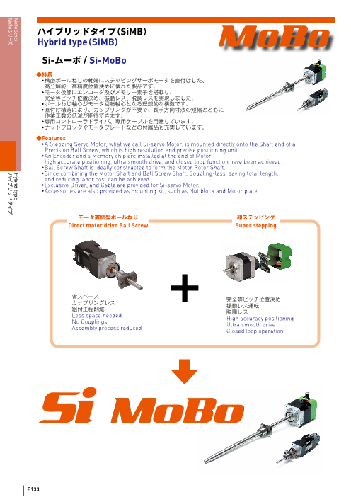
モータ直結型ボールねじ 超ステッピング
Direct motor drive Ball Screw Super stepping
省スペース
カップリングレス + 完全等ピッチ位置決め
組付工程削減 振動レス運転
Less space needed 脱調レス
No Couplings High accuracy positioning
Assembly process reduced Ultra smooth driveClosed loop operation
F133
MoBo Series Hybrid type
MoBo シリーズ ハイブリッドタイプ
Page2
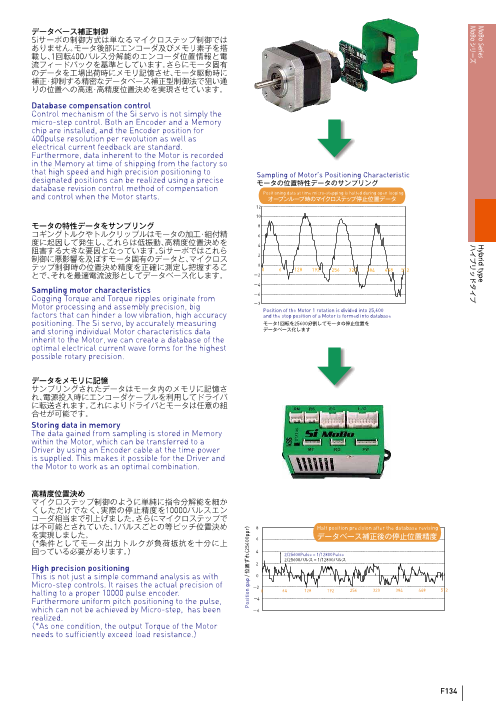
データベース補正制御
Siサーボの制御方式は単なるマイクロステップ制御では
ありません。モータ後部にエンコーダ及びメモリ素子を搭
載し、1回転400パルス分解能のエンコーダ位置情報と電
流フィードバックを基準としています。さらにモータ固有
のデータを工場出荷時にメモリ記憶させ、モータ駆動時に
補正・抑制する精密なデータベース補正型制御法で狙い通
りの位置への高速・高精度位置決めを実現させています。
Database compensation control
Control mechanism of the Si servo is not simply the
micro-step control. Both an Encoder and a Memory
chip are installed, and the Encoder position for
400pulse resolution per revolution as well as
electrical current feedback are standard.
Furthermore, data inherent to the Motor is recorded
in the Memory at time of shipping from the factory so
that high speed and high precision positioning to Sampling of Motor’s Positioning Characteristic
designated positions can be realized using a precise モータの位置特性データのサンプリング
database revision control method of compensation
and control when the Motor starts. Positioning data at time micro-stepping is halted during open loopingオープンループ時のマイクロステップ停止位置データ
12
10
モータの特性データをサンプリング 8
コギングトルクやトルクリップルはモータの加工・組付精 6
度に起因して発生し、これらは低振動、高精度位置決めを 4
阻害する大きな要因となっています。Siサーボではこれら
制御に悪影響を及ぼすモータ固有のデータと、マイクロス 2
テップ制御時の位置決め精度を正確に測定し把握するこ 0 0 6 128 192 256 320 384 448 512
とで、それを最適電流波形としてデータベース化します。 -2
-4
Sampling motor characteristics -6
Cogging Torque and Torque ripples originate from
Motor processing and assembly precision, big -3 Position of the Motor 1 rotation is divided into 25,600
factors that can hinder a low vibration, high accuracy and the stop position of a Motor is formed into database
positioning. The Si servo, by accurately measuring モータ1回転を25600分割してモータの停止位置を
and storing individual Motor characteristics data データベース化します
inherit to the Motor, we can create a database of the
optimal electrical current wave forms for the highest
possible rotary precision.
データをメモリに記憶
サンプリングされたデータはモータ内のメモリに記憶さ
れ、電源投入時にエンコーダケーブルを利用してドライバ
に転送されます。これによりドライバとモータは任意の組
合せが可能です。
Storing data in memory
The data gained from sampling is stored in Memory
within the Motor, which can be transferred to a
Driver by using an Encoder cable at the time power
is supplied. This makes it possible for the Driver and
the Motor to work as an optimal combination.
高精度位置決め
マイクロステップ制御のように単純に指令分解能を細か
くしただけでなく、実際の停止精度を10000パルスエン
コーダ相当まで引上げました。さらにマイクロステップで
は不可能とされていた、1パルスごとの等ピッチ位置決め 8 Halt position precision after the database revising
を実現しました。 6 データベース補正後の停止位置精度
(*条件としてモータ出力トルクが負荷抵抗を十分に上
回っている必要があります。) 4 2/25600Pulse = 1/12800Pulse
2/25600パルス = 1/12800パルス
2
High precision positioning
This is not just a simple command analysis as with 0
Micro-step controls. It raises the actual precision of -2
halting to a proper 10000 pulse encoder. 0 64 128 192 256 320 384 448 512
Furthermore uniform pitch positioning to the pulse, -4
which can not be achieved by Micro-step, has been -6
realized.
(*As one condition, the output Torque of the Motor
needs to sufficiently exceed load resistance.)
F134
Position gap / 位置ずれ(25600ppr)
MoBo Series Hybrid type
MoBo シリーズ ハイブリッドタイプ
Page3
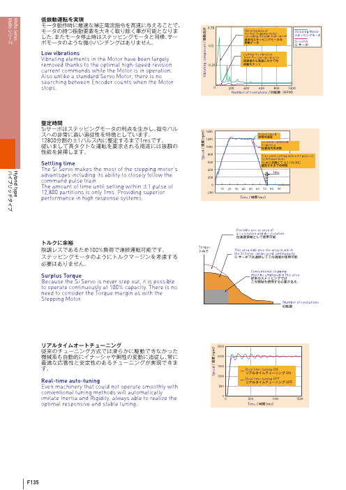
低振動運転を実現
モータ動作時に最適な補正電流指令を高速に与えることで、 0.75
モータの持つ振動要素を大きく取り除く事が可能となりま Vibrating data of normal stepping motor Steooing Motor
した。またモータ停止時はステッピングモータと同様、サー extending through high speed ステッピングモータ
ボモータのような微小ハンチングはありません。 通常のステッピングモータの振動データ Si-servo
0.5 Siサーボ
Low vibrations Cutting the vibration
Vibrating elements in the Motor have been largely from the low-speed area低速域から高速にかけての
removed thanks to the optimal high-speed revision 0.25 振動をカット
current commands while the Motor is in operation.
Also unlike a standard Servo Motor, there is no
searching between Encoder counts when the Motor
stops. 0 200 400 600 800 1000
Number of revolutions / 回転数(RPM)
整定時間
Siサーボはステッピングモータの利点を生かし、指令パル 1400
スへの非常に高い追従性を特徴としています。 Actual speed実際の速度
12800分割の±1パルス内に整定するまで1msです。 1200 Location command
従いまして高タクトな運転を要求される用途には抜群の frequency1000 位置指令周波数
性能を発揮します。 800 Time until settling within±1 pulse of
12,800 partitions
Settling time 600 12,800分割にて±1パルスに整定するまでの時間
The Si Servo makes the most of the stepping motor's 400
advantsges including its ability to closely follow the 1ms200
command pulse train
The amount of time until setting within ±1 pulse of 0 10 20 30 40 50 60 70 80 90
12,800 partitions is only 1ms. Providing superior -200
performance in high response systems. Time / 時間(ms)
Possible use as area of
acceleration and deceleration
加減速領域として使用可能
トルクに余裕
脱調レスであるため Torque100%負荷で連続運転可能です。 トルク This area indicates the area in which
the Si Servo can be used continuously
ステッピングモータのようにトルクマージンを考慮する Siサーボでは連続してこの領域が使用可能
必要はありません。
Conventional stepping
Surplus Torque must be employed in this area従来のステッピングでは
Because the Si Servo is never step out, it is possible この領域を使用する必要がある。
to operate continuously at 100% capacity. There is no
need to consider the Torque margin as with the
Stepping Motor.
Number of revolutions
回転数
リアルタイムオートチューニング 2500
従来のチューニング方式では滑らかに駆動できなかった
機械系も自動的にイナーシャや剛性の変動に追従し、常に 2000
最適な応答性と安定性のあるチューニングが実現できま
す。 1500 Real time tuning ON
リアルタイムチューニング ON
1000
Real-time auto-tuning Real time tuning OFFリアルタイムチューニング OFF
Even machinery that could not operate smoothly with 500
conventional tuning methods will automatically
imitate Inertia and Rigidity, always able to realize the 0 0 500 1000 1500
optimal responsive and stable tuning. Time / 時間(ms)
F135
Speed / 速度(rpm) Vibrating component / 振動成分
Speed / 速度(rpm)
MoBo Series Hybrid type
MoBo シリーズ ハイブリッドタイプ
Page4
ステッピングでトルク制御
位置制御をしながら5段階のトルク制御が行えます。 I/O Torque selection
ポイントテーブル運転では任意のトルク値の設定が可能
です。位置制御とトルク制御を自由に切り替えて使用でき I/Oでトルク選択
ますので、大変自由度の高い制御が可能となります。トル Pulse lineパルス列
ク制御中であっても内部にて偏差の管理を行っています
ので、位置がずれるようなことはありません。
L
Torque controls through stepping S M小 中 大
Five steps of Torque control are performed during
position control. Optional Torque value settings are
possible during the point table operations. A high
degree of freedom in control is possible thanks to
being able to switch back and forth between position
control and torque control. Even during Torque
control, differential controls are still being performed
internally, so positions will not deviate.
外部電子ギア切り替え
2段階の電子ギア設定を外部I/O信号または通信コマンド Electronic gear selection
で切り替えることが可能です。低い周波数の指令パルスし commands through I/O
か出力できないコントローラでも、高分解能で低速運転か I/Oで電子ギア選択命令
ら高速運転まで幅広い制御が可能となります。
External electronic gear transfer
Using external I/O signals and/or communication Pulse lineパルス列
commands, switching the electronicgear setting in
two steps possible. Even controller that cannot
output except on command pulses with low
frequencies can be highly functional in a wide range
from low speed to high speed operations.
*Switching can be performed while the motor is
halted.
ご使用条件によっては、本製品が適さない場合がありますので、KSSと十分な仕様打ち合わせをお奨めします。
Depends on the condition, this product will not be suitable for your specifications.
Please always consult with KSS due to the inquiry.
●基本仕様 / Specifications
Model Shaft Nominal Dia. Lead Travel Travel per pules Reference Thrust Mass
型 式 ねじ軸呼び外径 リード ストローク 1パルス移動量 参考推力 質量
(mm) (mm) (mm) (μm) (N) (g)
SiMB0401 φ4 1 30 1/25,600 30 114
SiMB0801 φ8 1 100 1/25,600 300 130
SiMB0802 φ8 2 160 2/25,600 150 165
SiMB0805 φ8 5 150 5/25,600 80 200
※くり返し位置決め精度及びロストモーションは
Repeatabilit(y reference) max. ±0.001mm 弊社標準ステージに組み付けた時の値です。
くり返し位置決め精度(参考値) 実力値についてはお問い合わせください。
※The reference value about Repeatability and Lost Motion
Lost Motion(reference)
max. 0.001mm represents when the MoBo built into KSS original actuator.
ロストモーション(参考値) Please make a contact to KSS for actual value.
注1)詳細寸法は、ページF147からの仕様図を参照ください。
注2)加減速レートは0.5ms/kH(z モータ単体性能)でのご使用を目安としてください。
注3)参考推力は条件により大きく変わることがありますので、KSSまでお問い合わせください。
Note1) Detail specifications & dimensions are shown in drawings from page F147.
Note2) Acceleration & Deceleration Rate should be recommended by 0.5ms/kHz or more(. Abiliby as a Motor itself)
Note3) Reference Thrust may vary depending on the operating condition, please ask KSS for more detail.
F136
MoBo Series Hybrid type
MoBo シリーズ ハイブリッドタイプ
Page5
●モータ仕様 / Motor Specifications
Model
型 式 TS3692N61S02(SiMB0401) TS3617N370S04(SiMB08xx)
Maximum output torque
最大出力トルク N・m 0.017 0.24
Maximum rotating speed
最大回転速度 rpm 4500 4500
Rated current
定格電流 A0-p 0.35 2.0
Rated voltage
定格電圧 V 3.0 2.2
Coil resistance
巻線抵抗 Ω 8.5±15% 1.1±15%
Rotor inductance
巻線インダクタンス mH 3.4±20% 1.4±20%
Rotor inertia -7 2
ロータイナーシャ 10 kg・m 1.9 35
Shaft run out
軸振れ mm T.I.R 0.05 0.05
Thrust play
スラストプレイ mm max. 0.01 0.01
Coil Method ― 2-phase hybird stepping motor Bipolar coil巻線方式 2相ハイブリッドステッピングモータ バイポーラ巻線
Insulation class
絶縁等級 ̶ CLASS B
Insulation resistance
絶縁抵抗 MΩ min. 100(at DC500V)
Dielectric strength
絶縁耐圧 V 500(at AC 1MIN)
Operating temperature range
使用温度範囲 ℃ -20~+50
Operating humidity range
使用相対湿度範囲 %RH 5~95
Storage temperature range
保存温度範囲 ℃ -40~+70
注)ロータイナーシャはボールねじ軸を含んだ値です。 Note ) Rotor Inertia includes Ball Screw Shaft.
●トルク特性 / Torque Characteristics
TS3692N61S02(□20) N-T Characteristics TS3617N370S04(□42) N-T Characteristics
N-T 特性 0.3 N-T 特性0.020
0.018 Continuation Area Acceleration / Deceleration Area
0.016 連続領域 加減速領域
0.014 0.2 Continuation Area
0.012 DC24V Supply
連続領域
0.010 DC24V Supply
0.008
0.006 0.1
0.004
0.002
0
0 1000 2000 3000 4000 0 1000 2000 3000 4000
Number of revolutions / 回転数(rpm) Number of revolutions / 回転数(rpm)
●ドライバ外形寸法 / Driver Outer Dimensions
39 Attachment hole 55 (3.7)
2-φ4 取付け穴
STATUS
3.8
45 10
F137
Torque / トルク(N・m)
88
70
80
70
Torque / トルク(N・m)
26.3 43.7
RM RS EC I/O
MT RG PW
MoBo Series Hybrid type
MoBo シリーズ ハイブリッドタイプ
Page6
●ドライバ仕様 / Driver Specifications
Model
型 式 Si-02LDE(SiMB0401) Si-02DE(SiMB08xx)
Applicable Motor Model
適応モータ型式 TS3692N61S02 TS3617N370S04
Rated Output Curren(t A0-p)
定格出力電流(A0-p) 0.35 2.0
Maximum Output Curren(t A0-p)
最大出力電流(A0-p) 1.0 4.5
Controlling Method Transistor PWM(Sine Wave Drive)
制御方式 トランジスタPWM(正弦波駆動)
Feedback Incremental Encoder 200 ppr Increnebtal Encoder 400ppr
フィードバック インクリメンタルエンコーダ200ppr インクリメンタルエンコーダ400ppr
Power supply
Voltage 動力電源 DC24V±10% or DC36V±10%
電源電圧
Power supply (V) Control power supply
制御電源 DC24V±10%電源
Power Supply Curren(t A)
電源電流(A) 2
Position Command Method Communication and Control Input through 3 Mode Pules Lines and RS485
位置指令方式 3モードパルス列、RS485による通信、制御入力、ポイントテーブルストアード方式
Temperature for Use
使用温度 0~+50℃
Storage Temperature
保存温度 -20~+85℃
Conditions
for Use Humidity for Use or Storage Under 90%RH(no condensation)
使用条件 使用・保存湿度 90%RH以下(結露なきこと)
Resistance Vibrations
耐振動 0.5G
Impact Resistance
耐衝撃 2G
Dynamic Braking None
ダイナミックブレーキ機能 なし
Regenerative Function Able to connect to external regeneration processing circuit
回生機能 外部に回生処理回路を接続可能
Standard Over Travle Prevention Hard OT, Soft OT(Select ON or OFF parameters)
Functions オーバトラベル防止機能 ハードOT、ソフトOT(パラメータにより有効 / 無効を選択)
内蔵機能
Internal Speed Setting Point Table Transfer Speed, Jog Speed, Reset Speed
内部速度設定機能 ポイントテーブル移動速度、ジョグ速度、原点復帰速度
Display 1- LED(Alarm Display, Servo ON Conditions)
表示機能 LED1点(アラーム表示、サーボON状態)
Control Input 5 points(Select function parameters)
制御入力 5点(パラメータで機能を選択)
Input CW / CCW、PULSE / SIGN、A / B Phase Inpu(t Select parameters)
Input / Output 入力 Command Pulse Input Maximum response waves : 750kpps
入出力 指令パルス入力 CW / CCW、PULSE / SIGN、A / B相入力(パラメータで選択)
最大応答周波数750kpps
Output Control output 3 points(Select parameters), Brake Release Signal
出力 制御出力 3点(パラメータで機能選択)、ブレーキ解除信号
EEPROM abnormalities, Encoder abnormalities, System abnormalities,
Protection Functions Over Currents, Driver overheating, Excessive location deviation,
保護機能 Motor current abnormalities, Control Current abnormalitiesEEPROM異常、エンコーダ異常、システム異常、過電流、ドライバ過熱、
位置偏差過大、モータ電源異常、制御電源異常
Zero Return Mode Zero LS Signal input or using mechanical stoppe(r Set parameters of 7 methods)
原点復帰方法 原点LS信号入力または機械端押し当て(パラメータにより7方式の選択)
Multi-axis Multi-drops of up to 15 axis with RS485
多軸接続機能 RS485による最大15軸までのマルチドロップ
Settigs Parameters are set through use of a compute(r RS485 converter required)
設定方式 パソコンを使用したパラメータ設定(RS485変換器が必要)
Standard, Environmental, and Protection Grades UL conformance / CE(self-declaration) / Corresponds to RoHS / IP40
規格、環境適合、保護等級 UL準拠 / CE(自己宣言) / RoHS対応 / IP40
F138
MoBo Series Hybrid type
MoBo シリーズ ハイブリッドタイプ
Page7
●接続 AC100V
Si-02LDE
ステータスランプ 電源ケーブル Si-02DE通信マスター モータ動力ケーブル(Si-PWBC□□M) (Si-MCB□□M)
REG1 PW
モータ動力 MT通信サブ 動力電源+ V1 1 + αAC 制御電源
- V2
1
2 - α
0V 2
3 + β
エンコーダ接続 3 EC14 4 - β
MT1
回生ユニット接続 REG2 E EC25 MM MT2
AC +
-
DC24V電源 外部入出力 EC
FG
1
回生ケーブル 2 TS3692N61S02
回生処理回路 (Si-RGVC) RG 3
TS3617N370S04
Si-RGVCK + P1 41 シールド線
■動力電源投入タイミング P2 5(オプション) C R 2
- 0V 6
動力電源(V1)と制御電源(V2)に別の電源を使用する場合、先に制御電源を投入して 3 DO_A7
ください。制御電源が投入されると制御開始信号としてOUT0信号をONにします。 I/Oケーブル NDO_A8
この信号の出力を確認してから動力電源を投入してください。 REG3 (Si-IOB□□M) I/O SK_BFG 9
動力電源と制御電源に同じ電源を使用(電源を並列にV1、V2端子に接続)する場合は + 1 NSK_B10
同時に投入して構いません。 AC - 2 SEL11
シールド線 3 NSEL
■電源投入時の初期化動作 124 DI_Z
BK2 13 モータエンコーダ
動力電源投入、OUT0信号のタイミングでサーボオン指令を与えてください。注3 5 NDI_ZPLC BK1 14 ケーブル
モータ励磁原点(機械角7.2°ごと)に位置決めを完了するとFIN/INP信号を出力し 6 Vc cCOME OUT 15 (Si-EB□□M)
初期化動作を完了します。注2 この初期化動作前に入力されたパルス列指令および 7 GNDOUT2 16
コマンドはすべて無視されます。また、ブレーキ解除信号はモータ励磁動作とのタ 8OUT1 9
イミングが計られた本装置の無電圧リレー接点出力BK1-BK2を必ずご使用ください。 COM OUT0 10
COM IN
11
IN4
Y 12IN3
制御電源入力(V2) 13
IN2
14
動力電源入力(V1) IN1 COM 15
IN0
16
制御開始信号出力(OUT0) CCWN
17
t1 t2 REG4 PLS CCWP
サーボオン入力( SVON) 18CWN
+ + 19CWP
モータ励磁 AC - - 20
RS485 スレーブケーブル
ブレーキ解除出力( BK1-BK2) RM RS (Si-RSS)
RS485 マスター TR X+
FIN / INP出力 ケーブル 1 1TR Xー
t3 t4 (Si-RSM□□M) 2 2 マルチドロップ時
GND
3 3 他のドライバの
FG RMコネクタと接続
■電源投入タイミング 4 4
(制御電源、動力電源の立上がり時間を考慮しない値です) USB-RS422/485 変換ユニット
記号 意味 時間 単位
t1 制御電源投入後、t1後にOUT0信号が出力されます 1000
t2 動力電源投入、t2後にモータ励磁可能状態となる注3 50 ※REG1は主回路電源用安定化電源でDC24VまたはDC36Vを使用する。
サーボオン指令後にモータ励磁を開始、最近傍のモータ
ms DC24Vの場合はREG2と共用可能。t3 励磁原点(機械角7.2°ごと)に位置決めを行います注1 500
同時にブレーキ解除信号を出力 ※REG2は制御回路用安定化電源でDC24Vを使用する。※REG3はI/O用安定化電源でDC24Vを使用する。
t4 ブレーキ解除信号出力後t4後にFIN/INP信号を パラメータ出力し初期化動作を完了します注2 53の値 ※REG4は指令パルス列をオープンコレクタ出力する場合の安定化電源でDC5V(またはそれ以上)を使用する。
注1)機械端にいる場合や、摩擦抵抗の強い機械の場合で、FIN/INP信号が出力された時点で ※BK1,2は無電圧リレー接点出力
モータ回転子が正確に励磁原点に位置決めできない場合、振動を発生したり規定のトルク ※MMはモータメモリユニットでTS3692N61S02、TS3641N61S02のみに
を出力できない可能性があります。その場合パラメータ53「起動時励磁ホールド時間」に ケーブル内に実装されている。
適当に大きな値を設定するか、パラメータ56「機械端検出シーケンス」を1に設定してく
ださい。
注2)パラメータ58「機械端検出シーケンス」を1に設定している場合、
t4終了後に機械端検出動作を開始し、完了にてFIN/INP信号を出力します。
注3)自動サーボオン機能が有効の場合、制御開始信号(OUT0)出力のオフと同時に
モータ励磁が開始されます。
制御入力選択一覧 制御出力選択一覧
選択機能 コード 内容 選択機能 コード 内容 選択機能 コード 内容 選択機能 コード 内容
SVON 01 サーボON SBK 18 シングルブロック RDY 01 サーボレディ P0_OUT 04
PJOG 02 正転JOG EXIN 1C 入力分岐 INP 02 インポジション P1_OUT 05
NJOG 03 逆転JOG EMCE 20 非常停止 ALM 03 アラーム P2_OUT 06(制御制動)
アラーム 非常停止 PRG 11 プログラム実行中 P3_OUT 20 現在ポイントARST 04 リセット EMCF 21 (サーボフリー) FIN 12 完了 P4_OUT 21 出力
STR 05 スタート EXIN2 23 入力分岐2 VCMP 1A 速度一致 P5_OUT 22
ZSTR 06 原点スタート EXIN3 24 入力分岐3 VZR 1B 0速度 P6_OUT 23
DEC 07 原点減速 STRP 25 スタート TFIN 1C トルク完了 P7_OUT 24(ワンショット入力)
原点スタート FIN+TFIN 1D 完了+トルク完了 P0_FIN 14HOLD 08 ホールド ZSTRP 26 (ワンショット入力) M0 30 P1_FIN 15
PO_IN 09 ERST 27 偏差クリア M1 31 M出力 P2_FIN 16
P1_IN 0A MFIN 28 M完了 M2 32 P3_FIN 28 ポイント完了
P2_IN 0B SENS 29 センサ位置決め TLMT 38 トルクリミット P4_FIN 29 出力
P3_IN 30 ポイント STP 2A 停止 SLMT 39 速度リミット P5_FIN 2A
P4_IN 31 番号入力 RSEL 38 分解能選択 POTOUT 3A 正転駆動禁止中 P6_FIN 2B
P5_IN 32 TSEL0 39 NOTOUT 3B 逆転駆動禁止中 P7_FIN 2C
P6_IN 33 TSEL1 3A ZFIN 3C 原点完了 ZPLS 3E Z相信号出力
P7_IN 34 TSEL2 3B トルク選択入力 ZERO 3D 原点位置出力 ー ー ー
TDIN 0C ティーチング TSEL3 3C パラメータ63に上記コードを指定します。
POT 12 正転OT TSEL4 3D パラメータ 63 OUT2 OUT1 OUT0※パラメータNo.60、61、63は32ビットのHEXデータとし、
NOT 13 逆転OT VDIR 2E 回転方向選択入力 8ビットづつに区切って各入出力の機能を設定します。
パラメータ60、61に上記コードを指定します。 機能が設定された場合、該当端子は設定された機能に割り当てられます。※複数の入力端子に同じ機能が割り当てられた場合、どちらか一方の入力が
パラメータ 60 IN3 IN2 IN1 IN0 あればその機能が実行されます。
※複数の出力端子に同じ機能が割り当てられた場合、その機能の出力は
パラメータ 61 IN4 設定された全ての端子に対して行われます。
F139
MoBo Series Hybrid type
MoBo シリーズ ハイブリッドタイプ
Page8
● AC100VConnections Si-02LDE
Power supply cable Si-02DE Motor power cable
Status Lamp Communication Master (Si-PWBC□□M) (Si-MCB□□M)
REG1 PW MT
Motor power Power supply V1Communication Sub + 1 + αAC
- Control power supply V2
1
2 - α
0V 2
3 + β
Regeneration Encoder Connection
3 EC1
- β MT14 4 EC2
Unit Connection REG2 E 5 MM MT2
AC +
-
DC24V EC
Power Supply External Input / Output FGRegeneration cable 1 TS3692N61S02
Regeneration (Si-RGVC)
2 TS3617N370S04
processing circuit RG 3
P1 4 Shield lineSi-RGVCK + 1
P2
■ 5Timing the introduction of activation power supply (option) C R 2- 0V 6
If using separate power supplies from activation(V1)and control( V2), introduce the 3 DO_A7
control power supply first. When the control is supplied, the OUT0 signal is turned on as I/O Cable NDO_A8
a signal that control has begun. Introduce the activation power supply only after REG3 (Si-IOB□□M) I/O SK_BFG
confiming the output from this signal. If using the same power supply for activation and 91 NSK_B
control(connecting the power supply to parallel V1 and V2 terminals), you can AC + 102 SEL
introduce them at the same time. - Shield line 113 NSEL
■ 12Initialization action when introducing power supply 4 DI_ZBK2 13
Give the command to turn on the servo timed with the introduction of the activation 5 NDI_Z Motor encoder cablePLC BK1 14
power supply and the OUT0 signal.*3 When the positioning of the motor excitation 6 Vc c (Si-ECB□□M)COME OUT 15
starting point( every 7.2° from the machine angle) is complate, the FIN/INP signal will 7 GND
be output and initialization actions are complete.*2All pulse line and other commands OUT2 168
input before these initialization actions will be ignored. Furthermore, be sure to use OUT1 9
non-voltage relay connection output BK1-BK2 on this device, where the brake COM OUT0 10
cancellation signal measures timing with the motor excitation activation. COM IN 11
IN4
Y 12IN3
Control power supply inpu(t V2) 13
IN2
14
Motor power supply input(V1) IN1
COM 15
IN0
Control starting point 16
signal output (OUT0) CCWN 17
t1 t2 PLS CCWP
Introduction of servo(SVON) REG4 18CWN
+ + 19
Motor excitation AC CWP- - 20
Brake cancellation( BK1-BK2) RS485 slave cableoutput RM RS (Si-RSS)
FIN / INP output +RS485 Master cable TR X 1 1
t3 t4 (Si-RSM□□M) TR Xー 2 2 When using multiple drops,
GND
3 3 connect with RM connectors
FG from other drivers■Power Supply Introduction Timing 4 4
(These value do not take into consideration times for starting control and activation power supplies)
USB-RS422/485 conversion unit
Symbol Meaning Time Unit
t1 Introduce control power supply, after t1 OUT0 signal is output. 1000
Introduce control power supply, after t2 conditions are set *REG1 uses either DC24V or DC36V for stabilizing power supply to the t2 for motor excitation*3 50 main circuit power supply. When DC24V is used, REG2 may be shared.
*REG2 uses DC24V for stabilizing power supply to the control circuit.
After the command to turn on servo, motor excitation *REG3 uses DC24V for stabilizing power supply to I/O.
t3 begins and positioning of the motor excitation starting
ms
poin(t every 7.2° from the machine angle) is perfomed.*1 500 *REG4 uses DC5V(or higher)for stabilizing power supply when the
The brake cancellation signal is output at the same time. command pulse line outputs an open collector.
*BK1 and 2 have no voltage relay connector output.
After the brake cancellation signal is output and t4, the *MM refers to motor memory unit, and is packaged only in cables
t4 FIN/INP signal is output and initialization actions are Value of
complete *2 Parameter 53 TS3692N61S02 and TS3641N61S02.
*1)If the motor rotor cannot accurately position the excitation starting point when the
FIN/INP signal is output because it is on the edge of the machine or because the
machine has a strong resistance to friction, this is a possibillity that vibrations may occur
or that the prescribed torque cannot be output. In this case, either set parameter 53,
"Time to Hold Excitation at start Time," to an appropriately large value, or set parameter
56, "Machine Edge Detection Sequence," to "1".
*2)If parameter 58, "Machine Edge Detection Sequence", is set to "1", after t4 is completed,
machine edge detection activities will begin and the FIN/INP signal will be output upon
completion.
*3)If the automatic servo on function is in effect, motor excitation will begin at the same
time the control start signa(l OUT0)output goes off.
Control Input Selection Table Control Output Selection Table
Selection Code Contents Selection Code Contents Selection SelectionFunction Function Function Code Contents Function Code Contents
SVON 01 Servo ON SBK 18 Single block RDY 01 Servo ready P0_OUT 04
PJOG 02 CW JOG EXIN 1C Input branching INP 02 In position P1_OUT 05
NJOG 03 CCW JOG EMCE 20 Emergency stop ALM 03 Alarm P2_OUT 06(control movement) PRG 11 Program in operation P3_OUT 20 Current point
ARST 04 Reset alarm EMCF 21 Emergen stop FIN 12 Completed P4_OUT 21 output(servo-free)
VCMP 1A Velocity agreement P5_OUT 22
STR 05 Start EXIN2 23 Input branching 2
VZR 1B Zero velocity P6_OUT 23
ZSTR 06 Zero start EXIN3 24 Input branching 3
TFIN 1C Torque completed P7_OUT 24
DEC 07 Deceleration STRP 25 Start(One-shot Input) FIN+TFIN 1D Completed and torque completed P0_FIN 14
HOLD 08 Hold ZSTRP 26 Zero start(one-shot Input) M0 30 P1_FIN 15
PO_IN 09 ERST 27 Clear deviation M1 31 M output P2_FIN 16
Point completion
P1_IN 0A MFIN 28 M Completion M2 32 P3_FIN 28 output
P2_IN 0B SENS 29 Sensor positioning TLMT 38 Torque limit P4_FIN 29
P3_IN 30 Point number STP 2A Stop SLMT 39 Speed limit P5_FIN 2A
P4_IN 31 input RSEL 38 Select resolution function POTOUT 3A Positive drive prohibited P6_FIN 2B
P5_IN 32 TSEL0 39 NOTOUT 3B Negative drive prohibited P7_FIN 2C
P6_IN 33 TSEL1 3A ZFIN 3C Zero complete ZPLS 3E Z phase signal
P7_IN 34 TSEL2 3B Torque selection outputinput
TDIN 0C Teaching TSEL3 3C ZERO 3D Zero position output ー ー ー
POT 12 CW OT TSEL4 3D Parameters 63 refer to the above codes.
Parameter 63 OUT2 OUT1 OUT0
NOT 13 CCW OT VDIR 2E Input selection for revolution direction *Parameter number 60, 61, and 63 are 32-bit hexadecimal data, and are divided
into 8 bits each, set through the input and output functions. When functions are
Parameters 60 and 61 refer to the above codes. set, the corresponding terminals are assigned to the set functions.
*When multiple input terminals are assigned to the same function,the one with
Parameter 60 IN3 IN2 IN1 IN0 input perfoms that function.
Parameter 61 IN4 *When multiple output terminals are assigned to the same function,the output from that function will be perfomed at all assigend terminals.
F140
MoBo Series Hybrid type
MoBo シリーズ ハイブリッドタイプ
Page9
●制御信号 / Control Signals
入力回路 / Input Circuit 出力回路 / Output Circuit
24V 24V
4.7kΩ Please prepare a separateinput circuitry power source RY
COM_IN of DC24V±10%
(11) (Crrent used : About 5mA/circuit)
Applied voltage : ≦30V
Electrified current : ≦50mA
5mA 入力回路電源は DC24V±10%を
別途ご準備ください 印加電圧 ≦30V
(消費電流 約 5mA/回路) COM_OUT 通電電流≦50mA
0V 0V (7)
パルス指令(5Vラインドライバ) パルス指令(5Vオープンコレクタ)
Pulse Command(5V Line Driver) Pulse Command(5V Open Collector)
CWP,CCWP 220Ω +5V CWP,CCWP 220Ω
1kΩ
15mA 15mA 1kΩ
CWN,CCWN CWN,CCWN
Applied line driver Use twists on P side and N side.
TI AM26C31 or equivalent P側と N側はツイスト処理をしてください。
適用ラインドライバ Use twists on P side and N side.
TI製 AM26C31相当品 P側と N側はツイスト処理をしてください。
Current used is about 15mA/circuit. 消費電流は約 15mA/回路 Pulse command(5V Open collector) パルス指令(5Vオープンコレクタ)
Please use a separate common 制御入出力とは電源コモンを別に Current used is about 15mA/circuit. 消費電流は約 15mA/回路
current for control input and output. 取ってください。
パルス指令(24Vオープンコレクタ)
ブレーキ信号 / Brake Signals Pulse Command(24V Open Collector)
Brake current
ブレーキ電源 5V 24V CWP,CCWP 220Ω
Brake coil / ブレーキコイル BK1
(6) 1.2kΩ 1kΩ
Surge absorption element 15mA
サージ吸収素子 RY CWN,CCWN
BK2
0V (5)
Use twists on P side and N side.
A non voltage contact output(1a) is used as the bracking cancellation signal.
The area between BK1 and BK2 shorts circuits when the motor is electrified. P側と N側はツイスト処理をしてください。
The applied voltage of the output terminal and the volume of electrified current
are as follows. When connected to an open 5V以上の電源でのオープン
・ Applied voltage : Under AC 125V, DC 60V collector output with current over 5V, コレクタ出力と接続する場合、
・Electrified current : Under 1A please attach a resister and restrict 電流制限抵抗を付加して電流を
・Please be sure to use a surge absorption unit of a varistor the current to 15mA. 15mAに制限してください。
type that meets the specifications of the brake coil being used.
Not iserting one may cause damage to the relay contact.
ブレーキ解除信号として、無電圧接点出力(1a)を用意しています。
モータ通電時に BK1-BK2間を短絡します。
出力端子の印加電圧、通電電流の容量は以下の通りです。
・印加電圧 AC125V、DC60V以下
・通電電流 1A以下
・ブレーキコイルにはブレーキコイルの仕様に見合った
バリスタ等のサージ吸収素子を必ず挿入してください。
挿入しない場合、リレー接点故障のおそれがあります。
通信仕様 通信プロトコル
準拠規格 2線式RS485
調歩同期式 ■送信(コントローラ⇒サーボ)
通信方式 キャラクタ方式 STX 軸 No ; COM ; データ ; データ EOT
半二重通信 終了コード(04h)
ボーレート 9600~115200bps データ
スタートビット 1 bit コマンド文字
区切りマーク(3Bh)
8 bit 軸番号(00~0E、7F※)
データ形式 ASCIIコード 先頭 コード(02h)
HEX ※軸番号に"7F"を指定すると、接続されているSi servo全てに対しコマンドを送信します。
パリティ 1 bi(t 偶数) この場合、Si servoから上位コントローラーに対する返信は通信エラーを含め一切行われません。
ストップピット 1 bit ■返信(サーボ⇒コントローラ)
サムチェック 無 データを返す場合 データを返さない場合
最大配線長 20m STX 軸 No ; COM ; データ EOT STX 軸 No ; COM EOT
接続軸数 15軸(No.0~E)
Communication Specifications Communication Protocol
Conforming Standards 2 line model RS485 ■Sending(Controller ⇒Servo)
Synchronous tones
Character method STX Axis No. ; COM ; Data ; Data EOTCommunication Methods
Half-duplex End of Transmission( 04h)
communication Data
Baud Rate 9600~115200bps Command letters
Delimiter( 3Bh)
Start bit 1 bit Axis Number( 00-0E, 7F*)
8 bit Start of Text( 02h)
Data form ASCII code * When the axis number is designated as 7F, commands are sent to all connected Si servos. In this case,
replies from the Si servo, including communication errors, to the upper controller will not be performed at all.
HEX
Parity 1 bi(t even) ■Replies(Servo⇒Controller)
Stop bit 1 bit When data is returned When data is not returned
Thumb check None STX Axis No.; COM ; Data EOT STX Axis No.; COM EOT
Maximum Cord Length 20m
Number of Connections 15 axis(No.0~E)
F141
MoBo Series Hybrid type
MoBo シリーズ ハイブリッドタイプ
Page10
●通信コマンド一覧
機能 コマンド 機能 コマンド 機能 コマンド 機能 コマンド
パラメータ読出 PRMR 原点スタートオン ZSTRON 拡張入力オン EXINON トルク選択3オン TSEL3ON
パラメータ書込 PRMW 原点スタートオフ ZSTROFF 拡張入力オフ EXINOFF トルク選択4オン TSEL4ON
ポイントテーブル読出 TR 原点スタートオンエッジ ZSTRP 拡張入力1オン EXIN1ON ポイント番号指定 PNT
ポイントテーブル書出 TW 原点減速オン DECOM 拡張入力1オフ EXIN1OFF 履歴クリア HCL
EEPROM書込 FLASH 原点減速オフ DECOFF 拡張入力2オン EXIN2ON トルクピークリセット TRST
サーボオン SVON ステップ送り STEPON 拡張入力2オフ EXIN2OFF 機械原点書換 ZSET
サーボオフ SVOFF ステップ送り停止 STEPOFF 拡張入力3オン EXIN3ON リセット RESET
非常停止オン EMCON ステップ送り0 STEP0ON 拡張入力3オフ EXIN3OFF 偏差カウンタセット ESET
非常停止オフ EMCOFF ステップ送り1 STEP1ON RSELON ティーチング TDIN
電子ギア選択
アラームリセット ARST ステップ送り2 STEP2ON RSELOFF 正転JOG PJOG
スタートオン STRON ステップ送り3 STEP3ON トルク選択 TSELON 逆転JOG NJOG
スタートオフ STROFF ポーズオン HOLDON トルク選択オフ TSELOFF JOG停止 JOGOFF
スタートオンエッジ STRP ポーズオフ HOLDOFF トルク選択0オン TSEL0ON I/Oモニタ IO
動作停止 STOP シングルブロックオン SBKON トルク選択1オン TSEL1ON I/Oモニタ2 IO2
数値モニタ MON シングルブロックオフ SBKOFF トルク選択2オン TSEL2ON アラーム発生状況 ALM
●Communication Command Table
Function Command Function Command Function Command Function Command
Read parameter PRMR Initial start ON ZSTRON Expansion Input ON EXINON Torque selectsion 3 ON TSEL3ON
Write parameter PRMW Initial start OFF ZSTROFF Expansion Input OFF EXINOFF Torque selecsion 4 ON TSEL4ON
Read point table TR Initial start on edge ZSTRP Expansion Input 1 ON EXIN1ON Designate point number PNT
Write point table TW Initial deceleration ON DECOM Expansion Input 1 OFF EXIN1OFF Clear history HCL
Write EEPROM FLASH Initial deceleration OFF DECOFF Expansion Input 2 ON EXIN2ON Reset torque selection TRST
Servo on SVON Step ON STEPON Expansion Input 2 OFF EXIN2OFF Rewrite machine start point ZSET
Servo off SVOFF Step OFF STEPOFF Expansion Input 3 ON EXIN3ON Reset RESET
Emergency stop ON EMCON Step 0 ON STEP0ON Expansion Input 3 OFF EXIN3OFF Set deviation counter ESET
Emargency stop OFF EMCOFF Step 1 ON STEP1ON RSELON Teaching TDIN
Electronic gear selection
Reset alarm ARST Step 2 ON STEP2ON RSELOFF CW JOG PJOG
Start ON STRON Step 3 ON STEP3ON Torque selection TSELON CCW JOG NJOG
Start OFF STROFF Hold ON HOLDON Torque selection OFF TSELOFF JOG OFF JOGOFF
Start on edge STRP Hold OFF HOLDOFF Torque selection 0 ON TSEL0ON I/O Monitor IO
Stop operations STOP Single block ON SBKON Torque selection 1 ON TSEL1ON I/O monitor 2 IO2
Numerical monitor MON Single block OFF SBKOFF Torque selecsion 2 ON TSEL2ON Alarm conditions ALM
F142
MoBo Series Hybrid type
MoBo シリーズ ハイブリッドタイプ
Page11
●パラメータ一覧表 ●Parameter Table
No. パラメータ名 再起動 単位 出荷値 No. Parameter Name Restart Unit Default setting
00 軸番号 ○ ー 0 00 Axis number ○ ー 0
01 制御入力機能プリセット設定 ○ ー 0 01 Preset control input function setting ○ ー 0
02 分解能分子 ○ パルス 12800 02 Resolution numerator ○ Pulse 12800
03 分解能分母 ○ パルス 1 03 Resolution denominator ○ Pulse 1
04 パルス列指令マルチプライ ○ ー 4 04 Pulse command multi-play ○ ー 4
06 正転ソフトOT パルス 0 06 CW soft OT Pulse 0
07 逆転ソフトOT パルス 0 07 CCW soft OT Pulse 0
08 カレントダウン電流 mA 2000※1 08 Current down mA 2000*1
09 カレントダウン時限 ms 100 09 Current down time limit ms 100
10 プリセットサーボゲイン選択 ー 1 10 Preset servo gain selection ー 1
11 位置比例ゲイン ー 50 11 Proportional position gain ー 50
12 位置フィードフォワード係数 ー 0 12 Position feed forword coefficient ー 0
13 速度比例ゲイン ー 10 13 Proportional speed gain ー 10
14 速度微分ゲイン ー 20 14 Differentiated speed gain ー 20
15 速度積分ゲイン ー 100 15 Integral speed gain ー 100
16 保持状態での積分動作 ー 1 16 Integral operations in hold condition ー 1
17 位置偏差最大値 パルス 6000 17 Maximum position deviation Pulse 6000
18 インポジション領域 パルス 2 18 In position area Pulse 2
19 トルク完了/VZR出力範囲 rpm 0 19 Torque complete / VZR output range rpm 0
20 入力パルス列種別 ○ ー 0 20 Input pulse differentiation ○ ー 0
21 ジョグ速度 rpm 300 21 JOG speed rpm 300
22 ジョグ加減速時定数 ms 10 22 JOG acceleration / deceleration time constants ms 10
23 ステップ送りパルス0 パルス 0 23 Step pulse 0 Pulse 0
24 ステップ送りパルス1 パルス 0 24 Step pulse 1 Pulse 0
25 ステップ送りパルス2 パルス 0 25 Step pulse 2 Pulse 0
26 ステップ送りパルス3 パルス 0 26 Step pulse 3 Pulse 0
27 原点復帰方式 ○ ー 0 27 Zero return method ○ ー 0
28 原点復帰方向 ○ ー 0 28 Zero return direction ○ ー 0
29 原点復帰高速速度 rpm 300 29 High-speed zero return rpm 300
30 原点復帰低速速度 rpm 180 30 Low speed zero return rpm 180
31 原点復帰加減速時定数 ms 500 31 Zero return acceleration / deceleration constants ms 500
32 原点復帰最終走行距離 パルス 12800 32 Zero return final distance Pulse 12800
33 原点復帰押し当てトルク % 50 33 Zero return pressing torque % 50
34 トルク制限時制限速度 rpm 4500 34 Torque control time and speed rpm 4500
35 トルク制限解除時制限速度 rpm 4500 35 Torque control cancellation time and speed rpm 4500
36 制限速度加減速時定数 ms 10 36 Control speed acceleration / deceleration constants ms 10
37 トルク指令増減時定数 ms 100 37 Torque command acceleration / deceleration constants ms 100
38 運転モード切替 ○ ー 0 38 Switch drive modes ○ ー 0
39 アラーム出力時定数 ms 100 39 Alarm output time constants ms 100
40 Z相出力時間 ms 10 40 Z-phase output time ms 10
41 制御入力フィルタ時定数 ms 5 41 Control input filter time constants ms 5
42 指令パルススムージングフィルタ時定数 ms 0 42 Command pulse smoothing filter time constants ms 0
43 通信フォーマット選択(bit) ○ ー 0h 43 Communication format selection(bit) ○ ー 0h
44 返信待ち時間 ms 50 44 Reply wait time ms 50
45 入力方式選択(bit) ○ ー 0h 45 Input method selection(bit) ○ ー 0h
47 サーボフリー遅延時間 ms 0 47 Servo free delay time ms 0
48 回転方向選択 ○ ー 0 48 Select revolution direction ○ ー 0
49 モータ電源電圧 ○ V 24 49 Motor voltage ○ V 24
50 オープンループ最高速度 rpm 15 50 Open loop maximum speed rpm 15
51 オープンループ最大位置偏差 エンコーダパルス 4 51 Open loop maximum position deviation Encoder Pulse 4
52 インポジション出力サンプリング時間 ms 0 52 In-position output sampling time ms 0
53 起動時励磁ホールド時間 ms 500 53 Magnetizations hold time at start ms 500
54 ポイント選択マルチプライ ー 0 54 Multi-play point selection ー 0
55 VCMP出力範囲 rpm 10 55 VCMP output range rpm 10
56 オートチューニング ー 0 56 Auto tuning ー 0
57 回転座標系パルス数 ○ パルス 0 57 Revolution coordinate system pulse number ○ Pulse 0
58 機械端検出シーケンス ○ ー 1 58 Machine terminal detection sequence ○ ー 1
59 グリッドマスクパルス数 エンコーダパルス 0 59 Number of grid mask pulses Encoder Pulse 0
60 拡張入力設定1(bit) ○ ー 3B3A3938h 60 Expansion input setting 1(bit) ○ ー 3B3A3938h
61 拡張入力設定2(bit) ○ ー 27h 61 Expansion input setting 2(bit) ○ ー 27h
63 拡張出力設定1(bit) ○ ー 3E031Dh 63 Expansion output setting 1(bit) ○ ー 3E031Dh
65 制御入力論理設定(bit) ○ ー 0h 65 Control input logic setting(bit) ○ ー 0h
66 制御出力論理設定(bit) ○ ー 0h 66 Control output logic setting(bit) ○ ー 0h
68 アラーム出力プロテクト ー 0h 68 Protect alarm output ー 0h
70 トルク選択0 % 300 70 Torque selection 0 % 300
71 トルク選択1 % 300 71 Torque selection 1 % 300
72 トルク選択2 % 300 72 Torque selection 2 % 300
73 トルク選択3 % 300 73 Torque selection 3 % 300
74 トルク選択4 % 300 74 Torque selection 4 % 300
75,76 正/逆トルクリミット※2 % 0 75,76 CW / CCW torque limit*2 % 0
※1)Si-02DEの出荷値です。(Si-02LDEの場合は350mAとなります。) *1)Value for Si-02DE.(It is 350mA for Si-02LDE.)
※2)75,76の値は0で300%と同じ意味を持ちます。 *2)Values for 75 and 76 are 0, but hold the same meaning as 300%.
注)「再起動」の欄に○のあるパラメーターの設定変更は電源再投入後に Note)Setting changes to parameters with a circle in the"Restart"
有効となります。 column are effective after the power supply is restored.
F143
MoBo Series Hybrid type
MoBo シリーズ ハイブリッドタイプ
Page12
●ケーブル仕様 / Cable Specifications
■モータケーブル / Motor cable : Si-MCB□□M
Si-02DE用、Si-02LDE用 / For Si-02DE, Si-02LDE コネクタ名 MT コネクタ名 MT1
端子番号 信号名 線色 端子番号 信号名 線色
□□m 1 +α 黒 1 +α 黒
50mm 50mm 2 -α 黒 / 白 2 -α 黒 / 白
Model number sticker
型式表示シール 3 +β 赤 3 +β 赤
4 -β 赤 / 白 4 -β 赤 / 白
UL2624 U-TKVV 22AWGx2P
Connector Connector
MT Connector MT1 Connector: EHR-4(JST) MT1 コネクタ : 172159-1(AMP) Name
MT Name MT1
MTコネクタ
Terminal Signal Color Terminal Signal Color
Shrinkable tube
収縮チューブ 1 +α Black 1 +α Black
2 -α Black / White 2 -α Black / White
3 +β Red 3 +β Red
4 -β Red / White 4 -β Red / White
■I/Oケーブル / I/O cable : Si-IOB□□M
コネクタ名 I/O コネクタ名 I/O
端子番号 信号名 線色 端子番号 信号名 線色
1 FG シールド 12 IN5 黄 / 白
2~4 空き ー 13 IN4 茶
5 BK2 黒 14 IN3 茶 / 白
6 BK1 黒 / 白 15 IN2 青
□□m
50mm 7 COM-OUT 赤 16 IN1 青 / 白
Model number sticker 8 ZPLS 赤 / 白 17 CCWN 灰
型番表示シール 9 ALM 緑 18 CCWP 灰 / 白
UL2624 U-TKVVBS 24AWGx10P 10 FIN/TSTBL 緑 / 白 19 CWN 橙
11 COM-IN 黄 20 CWP 橙 / 白
1st pin indication Shrinkable tube
1番極表示 収縮チューブ
I/O Connector
I/Oコネクタ : PADP-20V-1-S(JST) Connector Connector
Name I/O Name I/O
Terminal Signal Color Terminal Signal Color
1 FG shield 12 IN5 Yellow / White
2~4 Open ー 13 IN4 Brown
5 BK2 Black 14 IN3 Brown / White
6 BK1 Black / White 15 IN2 Blue
7 COM-OUT Red 16 IN1 Blue / White
8 ZPLS Red / White 17 CCWN Gray
9 ALM Green 18 CCWP Gray / White
10 FIN/TSTBL Green / White 19 CWN Orange
11 COM-IN Yellow 20 CWP Orange / White
■回生ケーブル / Regeneration cable : Si-RGVC
1000mm
50mm コネクタ名 RM Connector RM
Model number sticker Name
型式表示シール 端子番号 信号名 線色 Terminal Signal Color
UL2464(M) U-TKVV 22AWGx3C 1 P1 赤 1 P1 Red
2 P2 白 2 P2 White
3 0V 黒 3 0V Black
RG Connector
コネクタ : EHR-3(JST) Shrinkable tubeRG ※電源の極性に十分ご注意ください。 *Please note the polarity of the power supply.収縮チューブ 間違えますと、コントローラーを Mistakes may result in damege
破損する可能性があります。 to the controller.
※型式Si-RGVのケーブルを *If using the Si-RGV style cable,
ご使用の場合は配線色が異なり the wiring color will be different.
ますのでお問合わせください。 Please inquire.
F144
MoBo Series Hybrid type
MoBo シリーズ ハイブリッドタイプ
Page13
■エンコーダケーブル / Encoder cable : Si-ECB□□M
コネクタ名 EC コネクタ名 EC1
端子番号 信号名 線色 端子番号 信号名 線色
1 FG シールド 1 FG シールド
2~6 空き ー 2 空き ー
7 DO-A 黒 3 DO-A 黒
8 NDO-A 黒 / 白 4 NDO-A 黒 / 白
9 SK-B 赤 5 SK-B 赤
10 NSK-B 赤 / 白 6 NSK-B 赤 / 白
11 SEL 緑 7 SEL 緑
12 NSEL 緑 / 白 8 NSEL 緑 / 白
□□m 13 DI-X 黄 9 DI-Z 黄
50mm 50mm 14 NDI-Z 黄 / 白 10 NDI-Z 黄 / 白
Model number sticker
型番表示シール 15 Vcc 茶 11 Vcc 茶
16 GND 茶 / 白 12 GND 茶 / 白
UL2464 U-TKVVBS 24AWGx5P
Connector EC Connector Name Name EC11st pin indication EC1 ConnectorEC1コネクタ :172162-1(AMP)1番極表示 Shrinkable tube Terminal Signal Color Terminal Signal Color
EC Connector 収縮チューブ:PADP-16V-1-S(JST) 1 FG Shield 1 FG ShieldECコネクタ
2~6 ー ー 2 ー ー
7 DO-A Black 3 DO-A Black
8 NDO-A Black / White 4 NDO-A Black / White
9 SK-B Red 5 SK-B Red
10 NSK-B Red / White 6 NSK-B Red / White
11 SEL Green 7 SEL Green
12 NSEL Green / White 8 NSEL Green / White
13 DI-Z Yellow 9 DI-Z Yellow
14 NDI-Z Yellow / White 10 NDI-Z Yellow / White
15 Vcc Brown 11 Vcc Brown
16 GND Brown / White 12 GND Brown / White
■電源ケーブル / Power Supply cable : Si-PWBC□□M
Si-02DE用、Si-02LDE用
For Si-02DE, Si-02LDE コネクタ名 PW Connector Name PW
□□m 端子番号 信号名 線色 Terminal Signal Color
50mm 1 V1 赤 1 V1 Red
Model number sticker 2 V2 白 2 V2 White
型式表示シール
3 0V 黒 3 0V Black
UL2464 U-TKVV 22AWGx4C 4 空き ー 4 ー ー
5 E 緑 5 E Green
Shrinkable tube ※電源の極性に十分ご注意ください。 *Please note the polarity of the power supply.
PW Connector 収縮チューブ
PW コネクタ : EHR-5(JST) 間違えますと、コントローラーを Mistakes may result in damege
破損する可能性があります。 to the controller.
※型式Si-PWB□□Mのケーブルを *If using the Si-PWB□□M style cable,
ご使用の場合は配線色が異なり the wiring color will be different.
ますのでお問合わせください。 Please inquire.
■RS485マスターケーブル / RS485 Master cable : Si-RSM□□M
□□m コネクタ名 Connector 50mm RM Name RM
Model number sticker
型番表示シール 端子番号 信号名 線色 Terminal Signal Color
1 TRX+ 黒 1 TRX+ Black
UL2464 U-TKVVBS 24AWGx2P
2 TRX- 黒 / 白 2 TRX- Black / White
3 GND 赤 3 GND RedShrinkable tube
収縮チューブ
RM Connector 4 FG シールド 4 FG Shield
RMコネクタ : PAP-04V-S(JST)
■RS485スレーブケーブル / RS485 Slave cable : Si-RSS
コネクタ名 RS コネクタ名 RM
端子番号 信号名 線色 端子番号 信号名 線色
1 TRX+ 黒 1 TRX+ 黒
500mm
50mm 50mm 2 TRX- 黒 / 白 2 TRX- 黒 / 白
Model number sticker 3 GND 赤 3 GND 赤
型式表示シール 4 FG シールド 4 FG シールド
UL2464 U-TKVVBS 24AWGx2P
Connector Connector
Shrinkable tube
Name RS Name RM収縮チューブ
RS Connector
RSコネクタ :PAP-04V-S(JST)
RM Connector :PAP-04V-S(JST) Terminal Signal Color Terminal Signal ColorRMコネクタ
1 TRX+ Black 1 TRX+ Black
2 TRX- Black / White 2 TRX- Black / White
3 GND Red 3 GND Red
4 FG Shield 4 FG Shield
F145
MoBo Series Hybrid type
MoBo シリーズ ハイブリッドタイプ
Page14
●ポイントテーブル / Point Table
ポイントテーブル / Point Table
① ② ③ ④ ⑤ ⑥ ⑦ ⑧ ⑨ ⑨ ⑨ ⑩ ⑪ ⑫ ⑬ ⑭ ⑮
①絶対値/相対値 ①Abusolute Value / Relative Value
「位置/移動量」項目の設定値が絶対位置があるか相対移動量であるか The set value for "Position / Amount Moved" determines whether this is
を設定します。0を設定すると絶対位置、1を設定すると相対移動量で an absolute position or the amount of relative movement. "0"represents
動作します。 absolite location and "1" represents amount of relative movement.
②位置/移動量 ②Position / Amount Moved
位置/移動量を指令単位パルスで設定します。 This sets the location and amount of movement with the command
unit pulse
③速度データ ③Speed Data
移動速度をモータの回転速度rpmで設定します。 This sets the motor's revolution speed(rpm) for movement.
④加減速データ ④Acceleration / Deceleration Data
加減速時間を設定します。3000rpmに到達するまでの時間です。 This sets the time for acceleration and deceleration. It is time until
3000 rpm is achieved.
⑤待ち時間 ⑤Wait Time
次のポイント動作を開始するまでの待ち時間をms単位で設定します。 This sets the wait time until the next point's operation begins in units of
連続動作が有効になっていたりPRG終了の場合は無視されます。 ms. This is ignored in cases of continual operation or when the program
is completed.
⑥連続動作 ⑥Conitinual Operation
この動作が指定されている場合はそのポイントへの位置決め完了を When this setting is on, output of the command pulse for the next branch
待たず、すぐに次の分岐先の指令パルスを出力開始します。 begins immediately, without waiting for positioning of that point to be
completed.
⑦通常分岐 ⑦Normal Branching
ポイントへの位置決め完了後、次に実行するポイント番号を選択します。 This selects the next point number to run upon completion of the move.
⑧S字 ⑧S Curve
ポイント位置決めの加減速の速度曲線をSinカーブ(S字)に指定します。 This designates the speed curve's acceleration or deceleration for point
positioning to the S in curve(S curve).
⑨入力分岐1~3 ⑨Input Branch 1-3
外部入力EXIN(1~3)の状態がONのときの分岐先を指定します。 This designates the branch for when outer input EXIN(1-3) are ON.
⑩ループ回数(1~99回) ⑩Number of Loops(1-99)
分岐先の設定により繰返し運転を行う場合の回数を指定できます。 The number of loops can be designated according to branch settings
when repeated operations are perfomed.
⑪ループ後分岐 ⑪Branching after Loops
ループ回数で設定した回数を実行した後の分岐先を指定できます。 The branch location can be designated after the set number of loops
has completed the loop cycle.
⑫トルク設定 ⑫Torque Setting
このポイントへ移動するときのトルク設定(%)を行います。(0~300%) This perfoms the torque setting(%) when moving to this point(. 0-300%)
⑬センサ ⑬Sensor
センサ位置基準の位置決めを行う場合に設定します。 This sets the positioning for sensor position standard when perfoming
移動量に設定した値がセンサからの移動距離になります。 positioning. The value set for amount of movement is the distance
moved from the sensor.
⑭Mコード ⑭M code
外部への出力コードを3ビット(1~7)で指定できます。 An external output code can be designated in 3 bits(1-7).
位置決め開始時、位置決め完了時の出力タイミングの指定ができます。 The output timing for when positioning begins and finishes can be
designated.
⑮ループクリア ⑮Clear Loops
ループカウンタを0にクリアする場合に設定します。 Set when the loop counter is cleared to 0.
指令速度(rpm) 移動量相対値 ①
② Command speed( rpm)
Relative value, amount moved ①
3000 125000
通常位置決め ⑫&⑬ ポイント1 ⑦ 3000
125000 ②
Normal positioning Point 1 ⑦
⑫&⑬
速度100rpm ポイント0 Point 0Speed 100rpm
③ ③
STRまたは 加減速時間 10ms 待ち時間 1000ms STR or Time for 10msacceleration / deceleration Wait time 1000ms
コマンド[ON] ④&⑧ ⑤&⑥ Command [ON] ④&⑧ ⑤&⑥
FIN FIN
F146
MoBo Series Hybrid type
MoBo シリーズ ハイブリッドタイプ
Page15
Standard products in stock SiMB series Dimensions & Specifications
標準在庫品 SiMBシリーズ 寸法諸元
精密ボールねじ+エンコーダ付き2相ステッピングモータ / Precision Ball Screw + 2-phase Stepping Motor with Encoder
SiMB0401 Shaft dia(. 軸径)φ4 Lead(リード)1mm Trave(l ストローク)30mm
Connector / コネクタ(AMP)
Motoe power cable length / モータケーブル長さ : 300 Plug housing / プラグハウジング :172167-1
Pin / ピン : 170359-1
Encoder cable length / エンコーダケーブル長さ : 315
(52.5) 120 45 150
X 9 43.5
(Board size)
10 (基板サイズ) 35
13 1.5
3 (10)
0401(φ0.6)
Y Z Motor memory board
モータメモリ基板
C0.5 Heat-shrinkable tubing 90mm
収縮チューブ : 90mm
Y Z
X
48.5 (11.5)
15 Connector / コネクタ(AMP)
(60) 58.5 銘板 製造 No. Plug housing / プラグハウジング :172167-1
Identification Plate Pin / ピン : 170359-1
118.5
銘板 製造 No.
Identification Plate
(11)
2-φ2.9
PCD
14
11 View Z-Z
16 4-M2 Depth / 深さ 6 矢視 Z–Z
View Y-Y
矢視 20Y–Y
View X-X
矢視 X–X
注1)Si-MBは専用ドライバ(Si-02LDE)が必要です。 注2)軸端の切断のみ可能です。その他の軸端形状は受注生産品となります。
Note1)Exclusive Drive(r Si-02LDE)is required this type. Note2)Only shaft end cutting is available. Other than that, it would be customized order.
Motor side Supporting plate / モータ側サポートプレート MP-20A or MP-20B
Recommended accessories
推奨アクセサリー Supported side Bracket / 支持側ブラケット ―
Nut Block / ナットブロック NB-0401A
Ball Screw Specifications ボールねじ諸元 Motor Specifications モータ諸元
Accuracy grade
精度等級 JIS C3
Basic step angle
基本ステップ角 1.8°
Thread direction Right 右 Driving method 2-phase Bi-polar巻方向 励磁方式 2相バイポーラ方式
Axial play Rated Voltage
軸方向すきま 0 定格電圧 DC 3.0 V
Reference Thrust
参考推力 30N
Rated current
定格電流 DC 0.35A
Shaft material Stainless steel Winding resistance
ねじ軸材質 ステンレス鋼 巻線抵抗 8.5Ω
Nut material Chrome-molybdenum steel Holding Torque
ナット材質 クロムモリブデン鋼 ホールディングトルク 0.017Nm
Surface hardness Min. HRC55 Rotor inertia
ねじ部表面硬度 (Thread area) ロータイナーシャ 1.9g・cm
2
Lubricant KSS original grease MSG No.1 Operating temperature -20℃~ 50℃
潤滑剤 KSSオリジナルグリース MSG No.1 使用温度範囲
Encoder Incremental 200ppr
エンコーダ インクリメンタル 200ppr
F147
φ19
φ4
φ9g6 -0.005-0.014
φ17 0-0.020
16
20
φ18
(22) 12.5
(Board size)
(基板サイズ)
MoBo Series Hybrid type
MoBo シリーズ ハイブリッドタイプ
Page16
Standard products in stock SiMB series Dimensions & Specifications
標準在庫品 SiMBシリーズ 寸法諸元
精密ボールねじ+エンコーダ付き2相ステッピングモータ / Precision Ball Screw + 2-phase Stepping Motor with Encoder
SiMB0801 Shaft dia(. 軸径)φ8 Lead(リード)1mm Trave(l ストローク)100mm
Motor power cable / モータケーブル Encoder cable / エンコーダーケーブル
Connector / コネクタ(AMP) Connector / コネクタ(AMP)
Plug housing / プラグハウジング : 172167-1 Plug housing / プラグハウジング : 172170-1
Pin / ピン : 170359-1 Pin / ピン : 170359-1
AWG26
UL1430 AWG2620620(0)
UL tube / ULチューブ(Black / 黒φ5.3)
IWASE AH-3
(43) 20
8 35±1
15
2
(11) 4 Y X
0801(φ0.8)
C0
.5
0.5C
R0.2max 0.8 +0.1 0 .5
6.8 +0.1 C
0
0
Y X 銘板 製造 No.139 (12) Identification Plate 銘板 製造 No.
Identification Plate
9 (151)
(160) 55
215
4-M3 Depth / 深さ 4.5
2-φ3.4
CD 2
0
P φ53
15
View Y-Y
矢視 Y–Y
31±0.2
View X-X
42±0.3 矢視 X–X
注1)Si-MBは専用ドライバ(Si-02LDE)が必要です。 注2)軸端の切断のみ可能です。その他の軸端形状は受注生産品となります。
Note1)Exclusive Drive(r Si-02LDE)is required this type. Note2)Only shaft end cutting is available. Other than that, it would be customized order.
Motor side Supporting plate / モータ側サポートプレート MP-42A or MP-42B
Recommended accessories
推奨アクセサリー Supported side Bracket / 支持側ブラケット SP-42
Nut Block / ナットブロック NB-0801
Ball Screw Specifications ボールねじ諸元 Motor Specifications モータ諸元
Accuracy grade JIS C3 Basic step angle精度等級 基本ステップ角 1.8°
Thread direction Right 右 Driving method 2-phase Bi-polar巻方向 励磁方式 2相バイポーラ方式
Axial play 0 Rated Voltage軸方向すきま 定格電圧 DC 2.2 V
Reference Thrust Rated current
参考推力 300N 定格電流 DC 2.0A
Shaft material Stainless steel Winding resistance
ねじ軸材質 ステンレス鋼 巻線抵抗 1.1Ω
Nut material Chrome-molybdenum steel Holding Torque
ナット材質 クロムモリブデン鋼 ホールディングトルク 0.24Nm
Surface hardness Min. HRC55 Rotor inertia 2
ねじ部表面硬度 (Thread area) ロータイナーシャ 35g・cm
Lubricant Multemp PS-2 Operating temperature -20℃~ 50℃
潤滑剤 マルテンプ PS-2 使用温度範囲
Encoder Incremental 400ppr
エンコーダ インクリメンタル 400ppr
F148
φ6-0.002-0.010
φ5.7 0-0.06
φ8
φ13g6 -0.006-0.017
φ26
φ26.5
42±0.3 φ28 0-0.025
31±0.2
120
150+20 0
MoBo Series Hybrid type
MoBo シリーズ ハイブリッドタイプ
Page17
Standard products in stock SiMB series Dimensions & Specifications
標準在庫品 SiMBシリーズ 寸法諸元
精密ボールねじ+エンコーダ付き2相ステッピングモータ / Precision Ball Screw + 2-phase Stepping Motor with Encoder
SiMB0802 Shaft dia(. 軸径)φ8 Lead(リード)2mm Trave(l ストローク)160mm
Motor power cable / モータケーブル Encoder cable / エンコーダーケーブル
Connector / コネクタ(AMP) Connector / コネクタ(AMP)
Plug housing / プラグハウジング : 172167-1 Plug housing / プラグハウジング : 172170-1
Pin / ピン : 170359-1 Pin / ピン : 170359-1
AWG26
UL1430 AWG26
20620(0)
UL tube / ULチューブ(Black / 黒 φ5.3)
IWASE AH-3
(43) 20
8 35±1
18
2
(14) 4 Y X
0802(φ1.2)
C0
.5
+0.1 .5
R0.2max 0.8 0 C0
+0.1
6.8 C0
.5
0
銘板 製造 No.
189 (12) Identification Plate 銘板 製造 No.
Identification Plate
9 (201)
(210) 55
265
4-M3 Depth / 深さ 4.5
2-φ3.4
22 φ5
3
PCD
17
View Y-Y 31
矢視 ±0.2Y–Y View X-X
42±0.3 矢視 X–X
注1)Si-MBは専用ドライバ(Si-02LDE)が必要です。 注2)軸端の切断のみ可能です。その他の軸端形状は受注生産品となります。
Note1)Exclusive Drive(r Si-02LDE)is required this type. Note2)Only shaft end cutting is available. Other than that, it would be customized order.
Motor side Supporting plate / モータ側サポートプレート MP-42A or MP-42B
Recommended accessories
推奨アクセサリー Supported side Bracket / 支持側ブラケット SP-42
Nut Block / ナットブロック NB-0802
Ball Screw Specifications ボールねじ諸元 Motor Specifications モータ諸元
Accuracy grade JIS C3 Basic step angle精度等級 基本ステップ角 1.8°
Thread direction Right 右 Driving method 2-phase Bi-polar巻方向 励磁方式 2相バイポーラ方式
Axial play Rated Voltage
軸方向すきま 0 定格電圧 DC 2.2 V
Reference Thrust
参考推力 150N
Rated current
定格電流 DC 2.0A
Shaft material Stainless steel Winding resistance
ねじ軸材質 ステンレス鋼 巻線抵抗 1.1Ω
Nut material Chrome-molybdenum steel Holding Torque
ナット材質 クロムモリブデン鋼 ホールディングトルク 0.24Nm
Surface hardness Min. HRC55 Rotor inertia 2
ねじ部表面硬度 (Thread area) ロータイナーシャ 35g・cm
Lubricant Multemp PS-2 Operating temperature
潤滑剤 マルテンプ PS-2 使用温度範囲
-20℃~ 50℃
Encoder Incremental 400ppr
エンコーダ インクリメンタル 400ppr
F149
φ6 -0.002-0.010
φ5.7 0-0.06
φ8
φ -0.00615g6 -0.017
φ28
φ26.5
φ28 0-0.025
42±0.3
31±0.2
120
150+200
MoBo Series Hybrid type
MoBo シリーズ ハイブリッドタイプ
Page18
Standard products in stock SiMB series Dimensions & Specifications
標準在庫品 SiMBシリーズ 寸法諸元
精密ボールねじ+エンコーダ付き2相ステッピングモータ / Precision Ball Screw + 2-phase Stepping Motor with Encoder
SiMB0805 Shaft dia(. 軸径)φ8 Lead(リード)5mm Trave(l ストローク)150mm
Motor power cable / モータケーブル Encoder cable / エンコーダーケーブル
Connector / コネクタ(AMP) Connector / コネクタ(AMP)
Plug housing / プラグハウジング : 172167-1 Plug housing / プラグハウジング : 172170-1
Pin / ピン : 170359-1 Pin / ピン : 170359-1
AWG26
AWG26 20620(0)
UL1430
UL tube / ULチューブ(Black / 黒 φ5.3)
IWASE AH-3
(43) 20
8 35±1
28
2
(24) 4 Y
X
0805(φ1.5875)
C0
.5
+0.1
0.8 0
R0.2max .5
6.8 +0.1 C
0
0
C0
.5
Y X
188 (13) 銘板 製造 No.Identification Plate 銘板 製造 No.
9 Identification Plate(201)
(210) 55
265
4-M3 Depth / 深さ 4.5
2-φ3.4
3
D 25
φ5
PC
20
View Y-Y 31±0.2 View X-X
矢視 Y–Y
42±0.3 矢視 X–X
注1)Si-MBは専用ドライバ(Si-02LDE)が必要です。 注2)軸端の切断のみ可能です。その他の軸端形状は受注生産品となります。
Note1)Exclusive Drive(r Si-02LDE)is required this type. Note2)Only shaft end cutting is available. Other than that, it would be customized order.
Motor side Supporting plate / モータ側サポートプレート MP-42A or MP-42B
Recommended accessories
推奨アクセサリー Supported side Bracket / 支持側ブラケット SP-42
Nut Block / ナットブロック NB-0805
Ball Screw Specifications ボールねじ諸元 Motor Specifications モータ諸元
Accuracy grade JIS C3 Basic step angle精度等級 基本ステップ角 1.8°
Thread direction Right 右 Driving method 2-phase Bi-polar巻方向 励磁方式 2相バイポーラ方式
Axial play 0 Rated Voltage軸方向すきま 定格電圧 DC 2.2 V
Reference Thrust 80N Rated current参考推力 定格電流 DC 2.0A
Shaft material Stainless steel Winding resistance
ねじ軸材質 ステンレス鋼 巻線抵抗 1.1Ω
Nut material Chrome-molybdenum steel Holding Torque
ナット材質 クロムモリブデン鋼 ホールディングトルク 0.24Nm
Surface hardness Min. HRC55 Rotor inertia 2
ねじ部表面硬度 (Thread area) ロータイナーシャ 35g・cm
Lubricant Multemp PS-2 Operating temperature
潤滑剤 マルテンプ PS-2 使用温度範囲
-20℃~ 50℃
Encoder Incremental 400ppr
エンコーダ インクリメンタル 400ppr
F150
φ6 -0.002-0.010
φ5.7 0-0.06
φ8
φ18g6-0.006-0.017
φ31
φ26.5
φ28 0-0.025
42±0.3
31±0.2
120
150 +200
MoBo Series Hybrid type
MoBo シリーズ ハイブリッドタイプ
Page19
●使用上の注意
■ドライバに関するご注意
•制御盤内部温度が内蔵される機器による温度上昇を含めて、規定温度を超えないように冷却方法、配置、ボックスの
大きさを工夫してください。
•近くに震動源がある場合はショックアブソーバ等を取り付けることによりドライバに伝わる振動が規定値を
超えないように工夫してください。
•ドライバを2台以上複数台並べて配置する場合には、両側に20mm以上、上下に50mm以上の隙間を空けて
取り付けてください。隙間がとれない場合は、ファン等による強制空冷を行ってください。
•ドライバの電源再投入を行う際は、電源を切った後ドライバ電源LEDが完全に消灯したのを確認して再投入を
行ってください。短時間での電源再投入を連続すると、エンコーダメモリのデータ破壊につながります。
■モータに関するご注意
•リード線をつかみ、製品を持ち上げないでください。故障やケガの原因になります。
•リード線はすべて固定用です。可動用として使用しないでください。
•ねじ軸を叩いたり、規定を超えるスラスト荷重、ラジアル荷重を加えないでください。故障の原因となります。
•モータは防水、防油構造になっておりません。水や油が直接かかる所や、オイルバス状況下での使用はできません。
•有害なガスや液体、あるいは過度の湿度や水蒸気中では使用しないでください。また、振動や衝撃には十分に
注意してください。
•リード線の一部には静電気により破損する可能性がある部分(静電気対策マーク部分)があります。
該当部分には静電気の発生防止対策や取扱作業者の除電対策を実施してください。
■配線に関するご注意
•適合電線サイズ、種類及び最大配線長は規定値を超えないように配線してください。
•ノイズに対する措置として以下のことに注意してください。
1)リレー、電磁接触器、ソレノイドなどのコイルには必ずサージ吸収回路をつけてください。
2)パワーライン(ACライン、モータライン等)と信号ラインは30cm以上離して配線してください。
同一ダクト内に通したり、一緒に束線したりしないでください。
3)電気溶接機、放電加工機等と同一電源で使用しないでください。同一電源でなくても、近くに高周波雑音発生源が
ある場合には、電源及び入力回路にノイズフィルタをつけてください。
4)ドライバはスイッチングアンプを使用していますので、信号ラインにノイズがのることがあります。
•本ドライバはラジオ障害対策を施していませんので民家の近くやラジオ障害が問題になる場合は電源ラインに
ラインフィルタを入れてください。
•信号ラインに使用するケーブルは0.08~0.2mm2と細いため、電線に曲げ、張力がかからないようにしてください。
F151
MoBo Series Hybrid type
MoBo シリーズ ハイブリッドタイプ
Page20
●Handling precautions for Si-MoBo
■Cautions concerning Drivers
•Please arrange for cooling methods, locations, box size, etc., so that the standard temperature is not exceeded,
including temperature rises by equipment that has an internal temperature control panel.
•If located near a source of vibration, please arrage it so that vibrations transmitted to the driver do not exceed
standard values by attaching shock absorbers or the like.
•If two or more drivers are located together, please attach them with at least 20mm space on either side and
at least 50mm space vertically. If there is not enough space, please cool the area by using a fan or the like.
•When reinserting the power supply to the driver, please make the reinsertion after turning off the power supply
and checking that the power supply LED has completely gone out. If the power supply is renserted continuously
over a short period of time, the data in the encoder memory may be corrupted.
■Cautions concerning Motors
•Do not lift the merchandise by grabbing the lead wires. This may result in damege or injury.
•All lead wires are to be fixed. Do not use them as mobile objects.
•Do not hit the screw axis or increase the thrust load or radial load beyond standards.
This may result in damege or injury.
•The motor is not a structure that is either waterproof or oil proof. You cannot use it in a location where water or
oil may directly get on the motor or under oil bath conditions.
•Do not use near toxic gases or liquids, or in excessively humid or stamy conditions.
Also, please take sufficient care against vibrations or shocks.
•There is a part of the lead wire that is susceptible to damege by static electricity( the part marked for measures
against static electricity).
Please take measures to prevent static electricity or measures to eliminate static charges by workers.
■Cautions concerning wiring
•Please wire so that appropriate electric wire sizes, types and maximum wire length do not exceed
standard values.
•Please take note of the following as measures against noise.
1)Be sure to attach surge absorption circuits to coils such as relays,
electromagnet contact devices and solenoid.
2)Separate power lines(AC lines, motor lines, etc) and signal lines by 30cm or more.
Do not have them pass through the same duct or bunch them together.
3)Do not use with the same power supply as electrical welding machinery, electrical discharge machinery or
the like. Attach a noise filter to the power supply and the input circuits if a source of high frequency noise
is close by, even if the same power supply is not used.
4)Noise may occur in the signal line because the driver uses a switching amp.
•If problems occur near houses or with radios because this driver does not employ measures against radio
interference, insert a line filter into the power supply line.
•The cable used in signal lines is a thin 0.08-0.2mm2, so do not bend the wire or apply tension to it.
F152
MoBo Series Hybrid type
MoBo シリーズ ハイブリッドタイプ