


PCIe3.0 (Gen3) x8 バス • ピーク時バス帯域幅 7,800 MB/秒 • 持続バス帯域幅 6,700 MB/秒 • 帯域幅 50 Gbit/秒 (5,000 MB/秒)
関連メディア
このカタログについて
| ドキュメント名 | Coaxlink Octo PCIe 3.0 8 接続 CoaXPress フレームグラバー |
|---|---|
| ドキュメント種別 | 製品カタログ |
| ファイルサイズ | 958.1Kb |
| 登録カテゴリ | |
| 取り扱い企業 | Euresys Japan株式会社 (この企業の取り扱いカタログ一覧) |
この企業の関連カタログ


このカタログの内容
Page1
DATASHEET
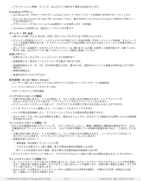
Coaxlink Octo
PCIe 3.0 8 接続 CoaXPress フレームグラバー
概要
• 8個のCoaXPress CXP-6接続: カメラ帯域幅 5,000 MB/秒
• 8台のCoaXPressカメラを1枚のカードに接続
• PCIe3.0 (Gen3) x8バス: バス帯域幅 6,700 MB/秒
• 機能が豊富なデジタル I/O ラインが10本
• 多種多様なカメラコントロール機能
• Memento Event Logging Tool
メリット
PCIe3.0 (Gen3) x8 バス
• ピーク時バス帯域幅 7,800 MB/秒
• 持続バス帯域幅 6,700 MB/秒
最速かつ最高解像度のカメラから画像を取得
• 業界最高のデータ取り込み速度
• カメラからホスト PC メモリまでの帯域幅 50 Gbit/秒 (5,000 MB/秒)
Coaxlink CXP-6のロングケーブルに対応
• 40メートル、CXP-6速度 (6.25 Gbps)
• 100メートル、CXP-3速度 (3 Gbps)
標準同軸ケーブルの使用
• データ転送、カメラ制御、トリガおよび電力のための廉価な1本のケーブル
• 過酷な環境でも極めて高い信頼性と柔軟性を提供
信頼性の高い接続を得る堅牢なコネクタ
• Coaxlink CXP-6ではプッシュプル式ラッチシステムを持つDIN 1.0/2.3コネクタを使用しています
最大 8 台のカメラを単一の Coaxlink カードに接続
Coaxlink Octoは、2枚のカードに接続された16接続カメラにも対応しています。
Memento Event Logging Tool
• Mementoは、先進開発であり、Coaxlinkカードで使用できるデバッグツールです。
• Mementoはカメラ、フレームグラバー、そのドライバ、およびアプリケーションに関連したイベントすべての正確な
ログを記録します。
• 開発者は、タイムスタンプされたイベントの正確なタイムラインを、コンテキスト情報とロジックアナライザビュー
とともに取得できます。
© EURESYS S.A. Subject to change without notice - 1 / 11 - Coaxlink Octo - 3602 - 2020-09-17 03:55
Page2
• アプリケーション開発、デバッグ、およびマシン動作中に重要な支援を行います。
CustomLogicデザイン
• CustomLogicは、FPGAコードのデザインとCoaxlinkボードへのアップロードを実現するFPGAデザインキットです
• Coaxlink OctoとCoaxlink Quad CXP-12に対応しており、最大70%のXilinx Kintex Ultrascale XCKU035 FPGAリソー
スを利用可能です。
• デザインフェーズでは、Xilinx Vivado開発ツールを使用します (非同梱)。
• CustomLogicの使用には、追加のハードウェアは不要です
ダイレクト GPU 転送
• AMD DirectGMA および NVIDIA (CUDA) 用サンプルプログラムをご利用いただけます。
• ダイレクトGPU転送によって、システムメモリの不要なコピー作成の排除、CPUオーバーヘッドの削減、さらにレーテ
ンシーの低減が実現するため、アプリケーションのデータ送出時間における大々的なパフォーマンス改善を得ること
ができます。
• GPU メモリへの画像データのダイレクトキャプチャーは AMD 製 DirectGMA を使用して実現可能です。AMD FirePro
W5x00 以降、およびすべての AMD FirePro S シリーズ製品と互換しています。
汎用I/Oライン
• 広範なセンサーおよびモーションエンコーダと互換性あり
• 高速差動入力:直交モーションエンコーダは最大5 MHzまで対応
• 絶縁電流検出入力:5V、12V、24Vの信号電圧に対応、最大50 kHz、個別のガルバニック絶縁は250VDCおよび170VAC
RMSまで。
• 絶縁非接触出力
• 高速5V対応TTL入力/LVTTL出力
高性能DMA(Direct Memory Access)
• ユーザーに割り当てられたメモリおよびPCIアドレスを持つハードウェアボードに直接転送
• ハードウェアのスキャッタギャザー対応
• 64ビットのアドレス割当機能
エリアスキャンのトリガ機能
• 対象が所定位置に来ると、トリガを使用して、ラインの取り込みが開始されます。ハードウェアトリガ
はCoaxlinkのI/Oラインから来ます。ソフトウェアトリガはアプリケーションから来ます。
• オプションのトリガディレイを使って、プログラマブルな時間だけ取り込みを遅らせることができます。
• トリガ デシメーション機能により、トリガのいくつかをスキップできます。
• カメラの露光調整機能により、アプリケーションでカメラの露光時間を調整できます。
• Coaxlinkボードは、取り込みを開始する際に、適当なタイミングで、出力ラインに接続された照明システムの制御信
号を発生させます。
ラインスキャンのトリガ機能 1/2
Coaxlinkは継続的なWebスキャンニング (ラインを失うことなく、無限に継続的に移動面の検査を行う) およ
び離散的なオブジェクトスキャンニング (カメラの前で移動している物体の画像を取り込む) に対応していま
す。
• 対象が所定位置に来ると、トリガを使用して、ラインの取り込みが開始されます。ハードウェアトリガはボード
のI/Oラインから来ます。ソフトウェアトリガはアプリケーションから来ます。
• 起動後の取り込みモード:
– 無限連続 (Web検査アプリケーション用)
– プログラム可能なライン数で連続 (長さが既知の物体の画像取り込み用)
– 終了トリガを受信するまで連続 (長さが異なる各種の物体の画像取り込み用)
• オプションのトリガディレイを使って、プログラマブルなライン数だけ取り込み開始を遅らせることができます。
ラインスキャンのトリガ機能 2/2
• モーションエンコーダから送られた信号に基づいて、Coaxlinkフレームグラバーがカメラスキャンニング率を調整し
ます。対象が速く移動する場合、カメラのライン取り込みレートが増加します。対象が遅く移動する場合、カメラの
ライン取り込みレートが減少します。
• Coaxlinkボードは直交モーションエンコーダから送信されたA/B信号を解釈し、対象がどの方向(前進または後
退)に移動しているのかを検知します。
© EURESYS S.A. Subject to change without notice - 2 / 11 - Coaxlink Octo - 3602 - 2020-09-17 03:55
Page3
• オプションとして、対象が前進したときのみまたは後進したときのみラインを取り込むようにCoaxlinkボードで設
定することができます。
• 後退モーションキャンセル機能を使用すると、後退する動きが検知されたときに取り込みが中止されます。対
象が再び前進し始めると、中止前とまったく同じ場所から取り込みを再開することができます。
• レート コンバーターを使用すると、モーションエンコーダの解像度よりも高いまたは低い任意の解像度(ユーザー
がプログラム可能)でラインを取り込むことができます。これにより、アプリケーション開発中の自由度や柔軟
性が非常に大きくなります。
• レート ディバイダ―により、カメラで、モーションエンコーダの解像度よりも低い解像度でラインを取り込むこと
が可能となります。レート ディバイダーはエンコーダからの入力信号の周波数を整数(ユーザーがプログラム可
能)で分割します。
レートコンバータを用いたフレキシブルなラインスキャンカメラの操作
• レートコンバータは、プログラム可能な高性能の周波数逓倍器/分割器です。
• モーションエンコーダおよびラインスキャンカメラと一緒に使用することで、画像ピクセルのアスペクト比を選択で
きます。
• 一続きの画像をキャリブレーションして、簡単にスクエアピクセル (アスペクト比1:1) を得ることができます。
Coaxlinkドライバには以下のツールが含まれます。
• Genicam</a></a>ブラウザ:システム内のGenTL Producerに装備されているGenICam機能にアクセスするためのアプリ
ケーション。
• GenTLコンソール:Euresys GenTL Producerに装備されている機能およびコマンドにアクセスするためのコマンドラ
インツール。
Genicam互換
以下に対応しています
• GenApi
• Standard Feature Naming Convention (SFNC)
• GenTL
Windows、Linux、およびmacOS用ドライバを提供
• Intel 32ビットおよび64ビットプラットフォームおよびARM 64ビットプラットフォームのサポートを含む
対応分野
電気機器産業向けマシンビジョン
• AOI、3D SPI、3Dリード/ボール検査機器向け高速画像取り込み
• フラットパネルディスプレイ検査および太陽電池検査向けの非常に高い画質のラインスキャン画像の取り込み
一般製造業向けマシンビジョン
• 検査装置用の高フレームレートの画像取り込み
• 表面検査装置用のラインスキャン画像取り込み
• 繊維検査装置用のラインスキャン画像取り込み
• ロボット用の画像取り込み
印刷産業向けマシンビジョン
• 印刷検査装置用の高速ラインスキャン画像取り込み
ビデオの取り込みと録画
• 動作分析および録画のための高フレームレートビデオ取り込み
ビデオモニター、監視&警備
• 交通の監視、モニターおよび管理のための長い同軸ケーブルによる高精細ビデオの転送および取り込み
仕様
Mechanical
Format Standard profile, half length, 8-lane PCI Express card
© EURESYS S.A. Subject to change without notice - 3 / 11 - Coaxlink Octo - 3602 - 2020-09-17 03:55
Page4
Cooling method Air cooling, fan-cooled heatsink
Mounting For insertion in a standard height, 8-lane or higher, PCI Express card slot
Connectors • 'A', 'B', 'C', 'D', 'E', 'F', 'G', 'H' on bracket:
– 8x DIN 1.0/2.3 female connectors
– CoaXPress host interface
• 'INTERNAL I/O' on PCB:
– 26-pin 2-row 0.1" pitch pin header with shrouding
– I/O lines and power output
• 'I/O EXTENSION' on PCB:
– 26-pin 2-row 0.05" pitch pin header with shrouding
– I/O extension lines and power output
• 'AUXILIARY POWER INPUT' on PCB:
– 6-pin PEG power socket
– 12 VDC power input for PoCXP camera(s) and I/O power
• 'C2C-LINK' on PCB:
– 6-pin 2-row 0.1-in header
– Card to card link
LED indicators • 'A', 'B', 'C', 'D', 'E', 'F', 'G', 'H' on bracket:
– Bi-color red/green LEDs
– CoaXPress Host connector indicator
• 'FPGA STATUS LAMP' on PCB:
– Bi-color red/green LED
– FPGA status indicator
• 'BOARD STATUS LAMP' on PCB:
– Bi-color red/green LED
– Board status indicator
Switches 'RECOVERY' on card PCB:
• 3-pin 1-row 0.1" header
• Firmware emergency recovery
Dimensions L 167.65 mm x H 111.15 mm
L 6.6 in x H 4.38 in
Weight 189 g, 6.67 oz
Host bus
Standard PCI Express 3.0
Link width • 8 lanes
• 1 lane, 2 lanes or 4 lanes with reduced performance
Link speed • 8.0 GT/s (PCIe 3.0)
• 5.0 GT/s (PCIe 2.0) with reduced performance
Maximum payload size 512 bytes
DMA 32- and 64-bit
Peak delivery bandwidth 7,800 MB/s
Effective (sustained) delivery 6,700 MB/s (Host PC motherboard dependent)
bandwidth
Power consumption Typ. 16 W (4.2 W @ +3.3V, 11.8 W @ +12V), excluding camera and I/O power output
Camera / video inputs
Interface standard(s) CoaXPress 1.0, 1.1 and 1.1.1
© EURESYS S.A. Subject to change without notice - 4 / 11 - Coaxlink Octo - 3602 - 2020-09-17 03:55
Page5
Connectors Eight DIN1.0/2.3 75 Ohms CXP-6
Status LEDs One CoaXPress Host connection status LED per connector
Number of cameras • Area-scan cameras:
– One 1- or 2- or 4- or 8-connection camera
– One or two 1- or 2- or 4-connection cameras
– Up to four 1- or 2-connection cameras
– One 1- or 2- or 4-connection camera and up to four 1-connection cameras
– Up to eight 1-connection cameras
• Line-scan cameras:
– One 1- or 2- or 4- or 8-connection camera
– One or two 1- or 2- or 4-connection cameras
– Up to four 1- or 2-connection cameras
Maximum aggregated camera data 50 Gbit/s (5,000 MB/s)
transfer rate
Supported CXP down-connection 1.25 GT/s (CXP-1), 2.5 GT/s (CXP-2), 3.125 GT/s (CXP-3), 5 GT/s (CXP-5), and 6.25 GT/s (CXP-6)
speeds
Number of CXP data streams (per 1 data stream per camera
camera)
Maximum CXP stream packet size 16,384 bytes
PoCXP (Power over CoaXPress) • PoCXP Safe Power:
– 17 W of 24V DC regulated power per CoaXPress connector
– PoCXP Device detection and automatic power-on
– Overload and short-circuit protections
• On-board 12V to 24V DC/DC converter
• A +12V power source must be connected to the AUXILIARY POWER INPUT connector using
a 6-pin PEG cable
Camera types • Area-scan cameras:
– Grayscale and color (YCbCr, YUV, RGB and Bayer CFA)
– Single-tap (1X-1Y) progressive-scan
• Line-scan cameras and contact imaging sensors:
– Grayscale and color RGB
Camera pixel formats supported Raw, Monochrome, Bayer, RGB, and RGBA (PFNC names):
• Raw
• Mono8, Mono10, Mono12, Mono14, Mono16
• BayerXX8, BayerXX10, BayerXX12, BayerXX14, BayerXX16 where XX = GR, RG, GB, or BG
• RGB8, RGB10, RGB12, RGB14, RGB16
• RGBA8, RGBA10, RGBA12, RGBA14, RGBA16
• YCbCr601_422_8, YCbCr601_422_10
• YCbCr709_422_8, YCbCr709_422_10
• YUV422_8, YUV422_10
Area-scan camera control
Trigger • Precise control of asynchronous reset cameras, with exposure control.
• Support of camera exposure/readout overlap.
• Support of external hardware trigger, with optional delay and trigger decimation.
Strobe • Accurate control of the strobe position for strobed light sources.
• Support of early and late strobe pulses.
© EURESYS S.A. Subject to change without notice - 5 / 11 - Coaxlink Octo - 3602 - 2020-09-17 03:55
Page6
Line-scan camera control
Scan/page trigger • Precise control of start-of-scan and end-of-scan triggers.
• Support of external hardware trigger, with optional delay.
• Support of infinite acquisition, without missing line, for web inspection applications.
Line trigger • Support for quadrature motion encoders, with programmable noise filters, selection of
acquisition direction and backward motion compensation.
• Rate Converter tool for fine control of the pixel aspect ratio: Rate Conversion Ratio in the
range 0.001 to 1000 with an accuracy better than 0.1%.
• Rate Divider tool
Line strobe • Accurate control of the strobe position for strobed light sources.
On-board processing
On-board memory 2 GB
Image data stream processing • Unpacking of 10-/12-/14-bit to 16-bit with selectable justification to LSb or MSb
• Optional swap of R and B components
• Little endian conversion
Flat-field correction Only available with the '2-camera' firmware variant
Input LUT (Lookup Table) Only available for monochrome cameras:
• 8 to 8 bits
• 10 to 8, 10 or 16 bits
• 12 to 8, 12 or 16 bits
Bayer CFA to RGB decoder • '1-camera' firmware variant:
– 3x3 linear interpolation method
– 3x3 median-based interpolation method
– 5x5 gradient-based interpolation method
• '2-camera' firmware variant:
– 3x3 linear interpolation method
– 3x3 median-based interpolation method
CustomLogic firmware variants • 1-camera, customlogic firmware variant
– one 1- or 2- or 4-connection area-scan camera
– 91% DSP, 84% FF, 75% LUT and 62% BRAM resources of the Xilinx Kintex Ultrascale
XCKU035 FPGA available for user programming
– 2GB capacity, 12GB/s bandwidth, shared on-board DRAM memory
Data stream statistics • Measurement of:
– Frame rate (Area-scan only)
– Line rate
– Data rate
• Configurable averaging interval
© EURESYS S.A. Subject to change without notice - 6 / 11 - Coaxlink Octo - 3602 - 2020-09-17 03:55
Page7
Event signaling and counting • The application software can be notified of the occurrence of various events:
– Standard event: the EVENT_NEW_BUFFER event notifies the application of newly
filled buffers
– A large set of custom events
• Custom events sources:
– I/O Toolbox events
– Camera and Illumination control events
– CoaXPress data stream events
– CoaXPress host interface events
• Each custom event is associated with a 32-bit counter that counts the number of
occurrences
• The last three 32-bit context data words of the event context data can be configured with
event-specific context data:
– Event-specific data
– State of all System I/O lines sampled at the event occurrence time
– Value of any event counter
General Purpose Inputs
and Outputs
Number of lines 10 I/O lines on INTERNAL I/O connector:
• 2 differential inputs (DIN)
• 2 singled-ended TTL inputs/outputs (TTLIO)
• 4 isolated inputs (IIN)
• 2 isolated outputs (IOUT)
NOTE: The number of I/O lines can be extended using I/O modules attached to the I/O
EXTENSION connector.
Usage • Any I/O input lines can be used by any LIN tool of the I/O Toolbox
• Selected pairs of I/O input lines can be used by any QDC tool of the I/O toolbox to decode
A/B signals of a motion encoder
• The LIN and QDC tools outputs can be further processed by the other tools (DIV, MDV,
DEL) of the I/O toolbox to generate any of the following "trigger" events:
– The "cycle trigger" of the Camera and Illumination controller
– The "cycle sequence trigger" of the Camera and Illumination controller
– The "start-of-scan trigger" of the Acquisition Controller (line-scan only)
– The "end-of-scan trigger" of the Acquisition Controller (line-scan only)
Electrical specifications • DIN: High-speed differential inputs compatible with ANSI/EIA/TIA-422/485 differential
line drivers and complementary TTL drivers
• TTLIO: High-speed 5V-compliant TTL inputs or LVTTL outputs, compatible with totem-
pole LVTTL, TTL, 5V CMOS drivers or LVTTL, TTL, 3V CMOS receivers
• IIN: Isolated current-sense inputs with wide voltage input range up to 30V, compatible
with totem-pole LVTTL, TTL, 5V CMOS drivers, RS-422 differential line drivers, potential
free contacts, solid-state relays and opto-couplers
• IOUT: Isolated contact outputs compatible with 30V / 100mA loads
Filter control • Glitch removal filter available on all System I/O input lines
• Configurable filter time constants:
– for DIN and TTLIO lines: 50 ns, 100 ns, 200 ns, 500 ns, 1 µs
– for IIN lines: 500 ns, 1 µs, 2 µs, 5 µs, 10 µs
Polarity control Yes
© EURESYS S.A. Subject to change without notice - 7 / 11 - Coaxlink Octo - 3602 - 2020-09-17 03:55
Page8
Power output • From AUXILIARY POWER connector to INTERNAL I/O and I/O EXTENSION connectors:
– Non-isolated +12V, 1A, with electronic fuse protection
• From PCI Express connector io I/O EXTENSION connector:
– Non-isolated, +3.3V, unprotected
I/O Toolbox tools The I/O Toolbox is a configurable interconnection of tools that generates events (usually
triggers) from input lines. The composition of the toolset is product- and firmware-
dependent.
• Line Input tool (LIN): Edge detector delivering events on rising or falling edges of any
selected input line.
• Quadrature Decoder tool (QDC): A composite tool including:
– A quadrature edge detector delivering events on selected transitions of selected pairs
of input lines.
– An optional backward motion compensator for clean line-scan image acquisition
when the motion is unstable.
– A 32-bit up/down counter for delivering a position value.
• Divider tool (DIV): to generate an event every nth input events from any I/O toolbox event
source.
• Multiplier/divider tool (MDV): to generate m events every d input events from any I/O
toolbox event source.
• Delay tool (DEL): to delay up to 16 events from one or two I/O toolbox event sources, by a
programmable time or number of motion encoder ticks (any QDC events).
• User Actions Scheduler tool (UAS): to delegate the execution of User Actions at a
scheduled time or encoder position. Possible user actions include setting
low/high/toggle any bit of the User Output Register or generation of any User Events.
I/O Toolbox composition Determined by the selected firmware variant:
• 1-camera: 8 LIN, 1 QDC, 1 DIV, 1 MDV, 2 DEL, 1 UAS
• 1-camera, line-scan: 8 LIN, 1 QDC, 1 DIV, 1 MDV, 2 DEL, 1 UAS
• 2-camera: 8 LIN, 1 QDC, 1 DIV, 1 MDV, 2 DEL, 1 UAS
• 2-camera, line-scan: 8 LIN, 1 QDC, 1 DIV, 1 MDV, 2 DEL, 1 UAS
• 4-camera: 8 LIN, 1 QDC, 1 DIV, 1 MDV, 2 DEL, 1 UAS
• 4-camera, line-scan: 8 LIN, 4 QDC, 4 DIV, 4 MDV, 4 DEL, 1 UAS
• 5-camera: 8 LIN, 1 QDC, 1 DIV, 1 MDV, 2 DEL, 1 UAS
• 8-camera: 8 LIN, 1 QDC, 1 DIV, 1 MDV, 2 DEL, 1 UAS
C2C-Link
Description • Accurate synchronization of the trigger and the start-of-exposure of multiple grabber-
controlled area-scan cameras.
• Accurate synchronization of the start-of-cycle, start-of-scan and end-of-scan of multiple
grabber-controlled line-scan cameras.
© EURESYS S.A. Subject to change without notice - 8 / 11 - Coaxlink Octo - 3602 - 2020-09-17 03:55
Page9
Specification • C2C-Link synchronizes cameras connected to:
– the same card
– to different cards in the same PC (requires an accessory cable such as the "3303 C2C-
Link Ribbon Cable" or a custom-made C2C-Link cable)
– to different cards in different PCs (requires one "1636 InterPC C2C-Link Adapter" for
each PC and one RJ 45 CAT 5 STP straight LAN cable for each adapter but the last one)
• Maximum distance:
– 60 cm inside a PC
– 1200 m cumulated adapter to adapter cable length
• Maximum trigger rate:
– 2.5 MHz for configurations using a single PC, or up to 10 PCs and 100 m total C2C-Link
cable length
– 200 kHz for configurations up to 32 PCs and 1200m total C2C-Link cable length
• Trigger propagation delay from master to slave devices:
– Less than 10 ns for cameras on the same card or on different cards in the same PC
– Less than 265 ns for cameras on different cards in different PCs (3 PCs and 40m total
C2C-Link cable length)
Software
Host PC Operating System • Microsoft Windows 10, 8.1, 7 for x86 (32-bit) and x86-64 (64-bit) processor architectures
• Linux for x86 (32-bit), x86-64 (64-bit) and aarch64 (64-bit) processor architectures
• macOS for x86-64 (64-bit) processor architecture
Refer to release notes for details
APIs EGrabber class, with C++ and .NET APIs:
• .NET assembly designed to be used with development environments compatible with
.NET frameworks version 4.0 or higher
GenICam GenTL producer libraries compatible with C/C++ compilers:
• x86 dynamic library designed to be used with ISO-compliant C/C++ compilers for the
development of x86 applications
• x86_64 dynamic library designed to be used with ISO-compliant C/C++ compilers for the
development of x86_64 applications
• aarch64 dynamic library designed to be used with ISO-compliant C/C++ compilers for the
development of aarch64 applications
Environmental conditions
Operating ambient air temperature 0 to +55 °C / +32 to +131 °F
Operating ambient air humidity 10 to 90% RH non-condensing
Storage ambient air temperature -20 to +70 °C/ -4 to +158 °F
Storage ambient air humidity 10% to 90% RH non-condensing
Certifications
Electromagnetic - EMC standards • European Council EMC Directive 2004/108/EC
• United States FCC rule 47 CFR 15
EMC - Emission • EN 55022:2010 Class B
• FCC 47 Part 15 Class B
EMC - Immunity • EN 55024:2010 Class B
• EN 61000-4-3
• EN 61000-4-4
• EN 61000-4-6
KC Certification Korean Radio Waves Act, Article 58-2, Clause 3
© EURESYS S.A. Subject to change without notice - 9 / 11 - Coaxlink Octo - 3602 - 2020-09-17 03:55
Page10
Flammability PCB compliant with UL 94 V-0
RoHS European Union Directive 2015/863 (ROHS3)
REACH European Union Regulation 1907/2006
WEEE Must be disposed of separately from normal household waste and must be recycled
according to local regulations
Ordering Information
Product code - Description • 3602 - Coaxlink Octo
Included accessories • 3304 - HD26F I/O Adapter Cable
Optional accessories • 1625 - DB25F I/O Adapter Cable
• 1636 - InterPC C2C-Link Adapter
• 3303 - C2C-Link Ribbon Cable
• 3610 - HD26F I/O Extension Module TTL-RS422
• 3612 - HD26F I/O Extension Module TTL-CMOS5V-RS422
• 3613 - JTAG Adapter Xilinx for Coaxlink
• 3614 - HD26F I/O Extension Module - Standard I/O Set
© EURESYS S.A. Subject to change without notice - 10 / 11 - Coaxlink Octo - 3602 - 2020-09-17 03:55
Page11
EMEA
Euresys SA
Liège Science Park - Rue du Bois Saint-Jean, 20
4102 Seraing - Belgium
Phone: +32 4 367 72 88
Email: sales.europe@euresys.com
EMEA
Sensor to Image GmbH
Lechtorstrasse 20 -
86956 Schongau - Germany
Phone: +49 8861 2369 0
Email: sales.europe@euresys.com
AMERICA
Euresys Inc.
27132-A Paseo Espada - Suite 421
San Juan Capistrano, CA 92675 - United States
Phone: +1 949 743 0612
Email: sales.americas@euresys.com
ASIA
Euresys Pte. Ltd.
750A Chai Chee Road - #07-15 Viva Business Park
Singapore 469001 - Singapore
Phone: +65 6445 4800
Email: sales.asia@euresys.com
CHINA
Euresys Shanghai Liaison Office
Unit 802, Tower B, Greenland The Center - No.500 Yunjin Road, Xuhui District
200232 Shanghai - China
Euresys上海联络处
上海市徐汇区云锦路500号绿地汇中心B座802室
200232
Phone: +86 21 33686220
Email: sales.china@euresys.com
JAPAN
Euresys Japan K.K.
Expert Office Shinyokohama - Nisso Dai 18 Building, Shinyokohama 3-7-18, Kohoku
Yokohama 222-0033 - Japan
〒222-0033
神奈川県横浜市港北区新横浜3-7-18 日総第18ビル エキスパートオフィス新横浜
Phone: +81 45 594 7259
Email: sales.japan@euresys.com
More at www.euresys.com
© EURESYS S.A. Subject to change without notice - 11 / 11 - Coaxlink Octo - 3602 - 2020-09-17 03:55