




Document Information
| Document Title | GDT Catalog |
|---|---|
| Document Type | Product Catalog |
| File size | 3.2Mb |
| Category | |
| Company | Sankosha Corporation (Documents List) |
Documents related to this company



Document Contents
Page1
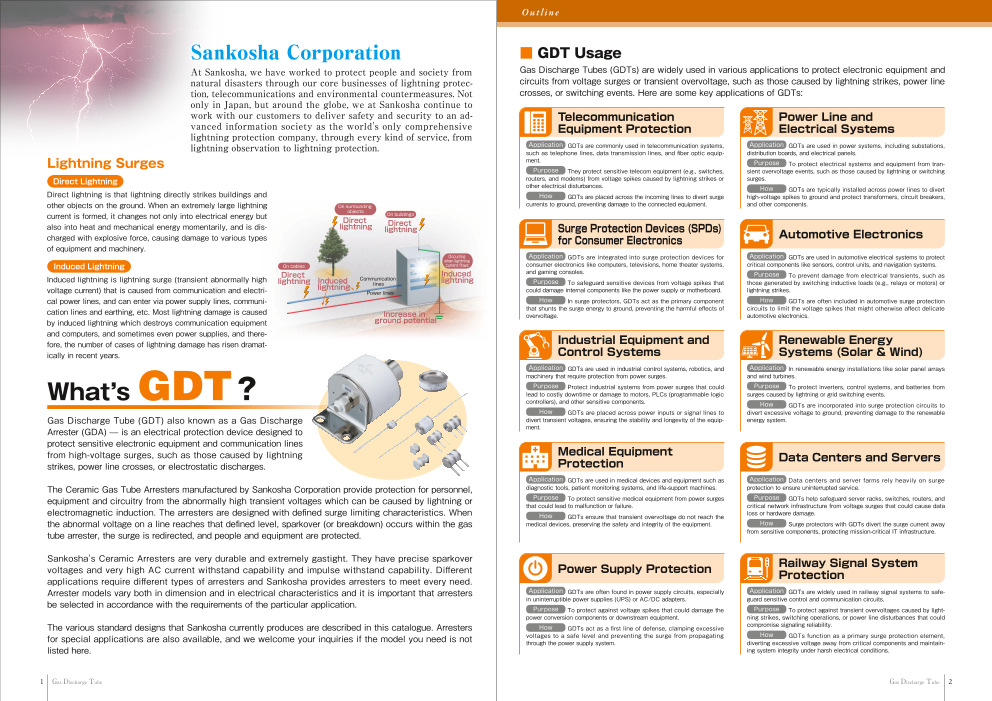
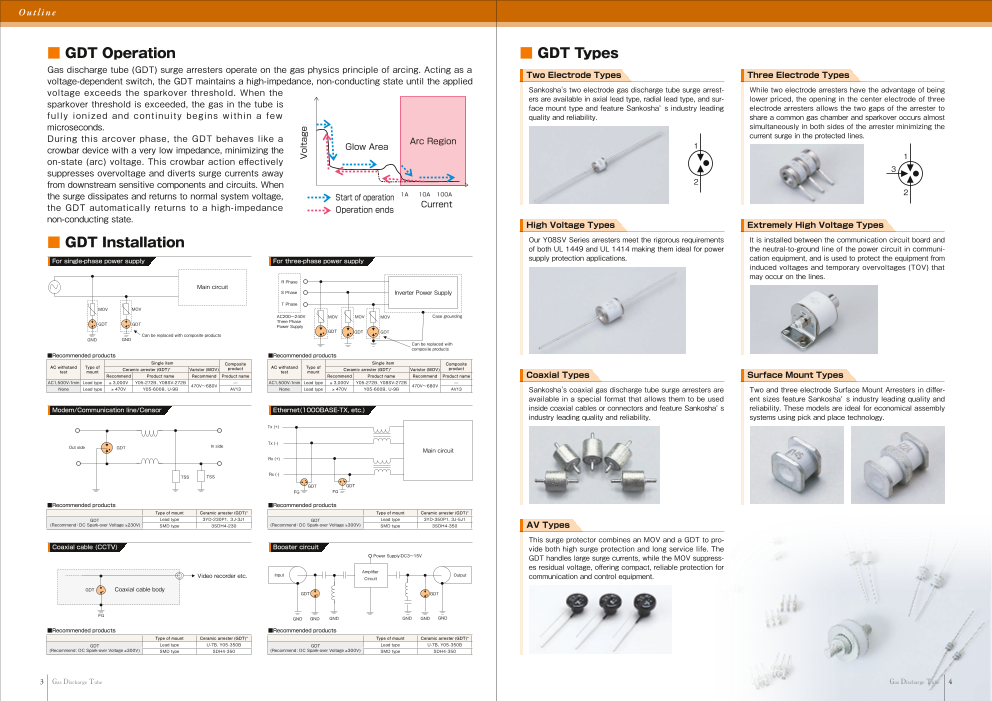
Catalog for
Lightning Protection
Versatile Applications of GDT:
From Power Device,Network Device to
Railway Signaling
as
ischarge
SANKOSHA proposes industry-leading lightning protection solutions.
Don’t hesitate to talk to us.
SANKOSHA Corporation: 2-11-1 Osaki, Shinagawa-ku, Tokyo 141-0032, Japan
English: https://www.sankosha.co.th/
Chinese: https://www.sankosha-gz.com/
Taiwan: https://https://www.sankosha-taiwan.com/
Thai: https://www.sankosha.co.th/th/
Indonesian: https://sankosha.co.id/
Vietnamese: https://sankosha.vn/
Korean: https://www.sankosha.kr/
Japanese: https://www.sankosha.co.jp/
● For printing reasons, the colors shown in the catalog may differ from those of the actual products.
● Thank you in advance for understanding that product specifications and external appearance may sometimes
undergo slight changes for the sake of improvement.
The content of this catalog is correct as of November 2025.
AD-166/25.11 ube
Page2
Out l i n e
Sankosha Corporation ■ GDT Usage
At Sankosha, we have worked to protect people and society from Gas Discharge Tubes (GDTs) are widely used in various applications to protect electronic equipment and
natural disasters through our core businesses of lightning protec- circuits from voltage surges or transient overvoltage, such as those caused by lightning strikes, power line
tion, telecommunications and environmental countermeasures. Not crosses, or switching events. Here are some key applications of GDTs:
only in Japan, but around the globe, we at Sankosha continue to
work with our customers to deliver safety and security to an ad- Telecommunication Power Line and
vanced information society as the world's only comprehensive Equipment Protection Electrical Systems
lightning protection company, through every kind of service, from
lightning observation to lightning protection. Application GDTs are commonly used in telecommunication systems, Application GDTs are used in power systems, including substations,
such as telephone lines, data transmission lines, and fiber optic equip- distribution boards, and electrical panels.
Lightning Surges ment. Purpose To protect electrical systems and equipment from tran-
Purpose They protect sensitive telecom equipment (e.g., switches, sient overvoltage events, such as those caused by lightning or switching
Direct Lightning routers, and modems) from voltage spikes caused by lightning strikes or surges.
other electrical disturbances. How GDTs are typically installed across power lines to divert
Direct lightning is that lightning directly strikes buildings and How GDTs are placed across the incoming lines to divert surge high-voltage spikes to ground and protect transformers, circuit breakers,
other objects on the ground. When an extremely large lightning On surrounding currents to ground, preventing damage to the connected equipment. and other components.
objects
current is formed, it changes not only into electrical energy but On buildings
Direct
also into heat and mechanical energy momentarily, and is dis- lightning Direct
lightning Surge Protection Devices (SPDs)
charged with explosive force, causing damage to various types for Consumer Electronics Automotive Electronics
of equipment and machinery.
Occurring Application GDTs are integrated into surge protection devices for Applicationwhen lightning GDTs are used in automotive electrical systems to protect
Induced Lightning On cables current flows: consumer electronics like computers, televisions, home theater systems, critical components like sensors, control units, and navigation systems.
and gaming consoles. PurposeInduced lightning is lightning surge (transient abnormally high Direct Induced
lightning Induced Communication lightning To prevent damage from electrical transients, such as
lightning lines Purpose To safeguard sensitive devices from voltage spikes that those generated by switching inductive loads (e.g., relays or motors) or
voltage current) that is caused from communication and electri- Power lines could damage internal components like the power supply or motherboard. lightning strikes.
cal power lines, and can enter via power supply lines, communi- How In surge protectors, GDTs act as the primary component How GDTs are often included in automotive surge protection
cation lines and earthing, etc. Most lightning damage is caused that shunts the surge energy to ground, preventing the harmful effects of circuits to limit the voltage spikes that might otherwise affect delicate
Increase in
by induced lightning which destroys communication equipment ground potential overvoltage. automotive electronics.
and computers, and sometimes even power supplies, and there-
fore, the number of cases of lightning damage has risen dramat- Industrial Equipment and Renewable Energy
ically in recent years. Control Systems Systems (Solar & Wind)
Application GDTs are used in industrial control systems, robotics, and Application In renewable energy installations like solar panel arrays
What’s GDT? machinery that require protection from power surges. and wind turbines.
Purpose Protect industrial systems from power surges that could Purpose To protect inverters, control systems, and batteries from
lead to costly downtime or damage to motors, PLCs (programmable logic surges caused by lightning or grid switching events.
controllers), and other sensitive components. How GDTs are incorporated into surge protection circuits to
How GDTs are placed across power inputs or signal lines to divert excessive voltage to ground, preventing damage to the renewable
Gas Discharge Tube (GDT) also known as a Gas Discharge divert transient voltages, ensuring the stability and longevity of the equip- energy system.
Arrester (GDA) ̶ is an electrical protection device designed to ment.
protect sensitive electronic equipment and communication lines
from high-voltage surges, such as those caused by lightning Medical Equipment
strikes, power line crosses, or electrostatic discharges. Protection Data Centers and Servers
Application GDTs are used in medical devices and equipment such as Application Data centers and server farms rely heavily on surge
The Ceramic Gas Tube Arresters manufactured by Sankosha Corporation provide protection for personnel, diagnostic tools, patient monitoring systems, and life-support machines. protection to ensure uninterrupted service.
equipment and circuitry from the abnormally high transient voltages which can be caused by lightning or Purpose To protect sensitive medical equipment from power surges Purpose GDTs help safeguard server racks, switches, routers, and
that could lead to malfunction or failure. critical network infrastructure from voltage surges that could cause data
electromagnetic induction. The arresters are designed with defined surge limiting characteristics. When How GDTs ensure that transient overvoltage do not reach the loss or hardware damage.
the abnormal voltage on a line reaches that defined level, sparkover (or breakdown) occurs within the gas medical devices, preserving the safety and integrity of the equipment. How Surge protectors with GDTs divert the surge current away
tube arrester, the surge is redirected, and people and equipment are protected. from sensitive components, protecting mission-critical IT infrastructure.
Sankosha's Ceramic Arresters are very durable and extremely gastight. They have precise sparkover
voltages and very high AC current withstand capability and impulse withstand capability. Different Power Supply Protection Railway Signal System
applications require different types of arresters and Sankosha provides arresters to meet every need. Protection
Arrester models vary both in dimension and in electrical characteristics and it is important that arresters Application GDTs are often found in power supply circuits, especially Application GDTs are widely used in railway signal systems to safe-
in uninterruptible power supplies (UPS) or AC/DC adapters. guard sensitive control and communication circuits.
be selected in accordance with the requirements of the particular application.
Purpose To protect against voltage spikes that could damage the Purpose To protect against transient overvoltages caused by light-
power conversion components or downstream equipment. ning strikes, switching operations, or power line disturbances that could
The various standard designs that Sankosha currently produces are described in this catalogue. Arresters How GDTs act as a first line of defense, clamping excessive compromise signaling reliability.
for special applications are also available, and we welcome your inquiries if the model you need is not voltages to a safe level and preventing the surge from propagating How GDTs function as a primary surge protection element,
through the power supply system. diverting excessive voltage away from critical components and maintain-
listed here. ing system integrity under harsh electrical conditions.
1 Gas Discharge Tube Gas Discharge Tube 2
Page3
Out l i n e
■ GDT Operation ■ GDT Types
Gas discharge tube (GDT) surge arresters operate on the gas physics principle of arcing. Acting as a Two Electrode Types Three Electrode Types
voltage-dependent switch, the GDT maintains a high-impedance, non-conducting state until the applied
voltage exceeds the sparkover threshold. When the Sankosha's two electrode gas discharge tube surge arrest- While two electrode arresters have the advantage of being
sparkover threshold is exceeded, the gas in the tube is ers are available in axial lead type, radial lead type, and sur- lower priced, the opening in the center electrode of three
face mount type and feature Sankosha’ s industry leading electrode arresters allows the two gaps of the arrester to
fu l ly ion ized and cont inu i ty begins wi th in a few quality and reliability. share a common gas chamber and sparkover occurs almost
microseconds. simultaneously in both sides of the arrester minimizing the
During this arcover phase, the GDT behaves like a current surge in the protected lines.
Glow Area Arc Region
crowbar device with a very low impedance, minimizing the 1
on-state (arc) voltage. This crowbar action effectively 1
suppresses overvoltage and diverts surge currents away 3
from downstream sensitive components and circuits. When 2
the surge dissipates and returns to normal system voltage, Start of operation 1A 10A 100A 2
the GDT automatically returns to a high-impedance Operation ends Current
non-conducting state.
High Voltage Types Extremely High Voltage Types
■ GDT Installation Our Y08SV Series arresters meet the rigorous requirements It is installed between the communication circuit board and
of both UL 1449 and UL 1414 making them ideal for power the neutral-to-ground line of the power circuit in communi-
For single-phase power supply For three-phase power supply supply protection applications. cation equipment, and is used to protect the equipment from
induced voltages and temporary overvoltages (TOV) that
may occur on the lines.
R Phase
Main circuit
S Phase Inverter Power Supply
T Phase
MOV MOV
AC200~240V MOV MOV MOV Case grounding
GDT GDT Three Phase
Power Supply
GDT GDT GDT
Can be replaced with composite products
GND GND
Can be replaced with
Single item composite products
Composite Single item Composite
■ARCe wcitohmstamnde ndeTdyp ep roof ducts Ceramic arrester (GDT)* Varistor (MOV) product ■ARCe wcitohmstamnde ndeTdyp ep roof ducts
test mount test mount Ceramic arrester (GDT)* Varistor (MOV) product
Recommend ProSdinugclte niatemme Recommend PrCoodmucpto nsaitme e Recommend ProSdinugclte niatemme Recommend PrCoodmucpto nsaitme e
AC withstand Type of Ceramic arrester (GDT)* Varistor (MOV) product AC withstand Type of
AC1,5t0e0stV-1min Lemaodu tnytpe 3,000V Y05-272B、Y08SV-272B ̶ AC1,500V-1min Lead type 3,00C0VeramYic0 a5r-r2e7st2eBr 、(GYD0T8S)*V-272B Varistor (MOV) pro̶duct
470V~680V test mount
Recommend Product name Recommend Product name 470V~680V
None Lead type 470V Y05-600B、U-9B AV13 None Lead type Rec o4m7m0Vend Y0P5ro-6d0uc0tB n、aUm-e9B Recommend ProdAuVc1t 3name Coaxial Types Surface Mount Types
AC1,500V-1min Lead type 3,000V Y05-272B、Y08SV-272B ̶ AC1,500V-1min Lead type 3,000V Y05-272B、Y08SV-272B ̶
470V~680V 470V~680V
None Lead type 470V Y05-600B、U-9B AV13 None Lead type 470V Y05-600B、U-9B AV13 Sankosha's coaxial gas discharge tube surge arresters are Two and three electrode Surface Mount Arresters in differ-
available in a special format that allows them to be used ent sizes feature Sankosha’ s industry leading quality and
Modem/Communication line/Censor Ethernet(1000BASE-TX, etc.) inside coaxial cables or connectors and feature Sankosha’ s reliability. These models are ideal for economical assembly
industry leading quality and reliability. systems using pick and place technology.
Tx (+)
Tx (-)
Out side GDT In side
Main circuit
Rx (+)
TSS TSS Rx (-)
GDT GDT
FG FG
Type of mount Ceramic arrester (GDT)* Type of mount Ceramic arrester (GDT)*
■Recommended products Lead type 3YD-230P1、3J-3J1 ■Recommended products
GDT GDT Lead type 3YD-350P1、3J-5J1
(Recommend:DC Spark-over Voltage 230V) TySpeM oDf tmypoeunt Ceram3icS DarHre4s-t2e3r 0(GDT)* (Recommend:DC Spark-over Voltage 300V) TySpeM oDf tmypoeunt Ceram3icS DarHre4s-t3e5r 0(GDT)*
GDT Lead type 3YD-230P1、3J-3J1 GDT Lead type 3YD-350P1、3J-5J1
(Recommend:DC Spark-over Voltage 230V) SMD type 3SDH4-230 (Recommend:DC Spark-over Voltage 300V) SMD type 3SDH4-350 AV Types
This surge protector combines an MOV and a GDT to pro-
Coaxial cable (CCTV) Booster circuit vide both high surge protection and long service life. The
Power Supply:DC3~15V GDT handles large surge currents, while the MOV suppress-
es residual voltage, offering compact, reliable protection for
Amplifier
Video recorder etc. Input Output
Circuit communication and control equipment.
GDT Coaxial cable body
GDT GDT
FG
GND GND GND GND GND GND
■Recommended products ■Recommended products
Type of mount Ceramic arrester (GDT)* Type of mount Ceramic arrester (GDT)*
GDT Lead type U-7B、Y05-350B GDT Lead type U-7B、Y05-350B
(Recommend:DC Spark-over Voltage 300V) TySpeM oDf tmypoeunt CeramSicD aHrr4e-s3te5r0 (GDT)* (Recommend:DC Spark-over Voltage 300V) TySpeM oDf tmypoeunt CeramSicD aHrr4e-s3te5r0 (GDT)*
GDT Lead type U-7B、Y05-350B GDT Lead type U-7B、Y05-350B
(Recommend:DC Spark-over Voltage 300V) SMD type SDH4-350 (Recommend:DC Spark-over Voltage 300V) SMD type SDH4-350
3 Gas Discharge Tube Gas Discharge Tube 4
Voltage
Page4
Out l i n e Produ c t s
■ GDT VS Other Anti-Surge Components ■ Lightning protective elements
Compares GDTs with other surge protection components in terms of electrical characteristics and GDT (Gas Discharge Tube) Ceramic arrester
physical dimensions. GDTs feature a high current- withstand capability and very low capacitance These lightning protective elements utilize the electrical discharge phenomenon that occurs across the
compared to other devices. electrodes disposed within the ceramic arresters to inhibit surge voltage entering communication lines and
signaling lines.
GDT Varistor SP Diode / TVS Diodes
Surge preventive devices
Item
Standard Standard Low
Working voltage
About 600V ~ 12kV About 30V ~ 5kV About 5V ~ 300V
Large Standard Small
Current withstand capacity
5kA ~ 100kA 50A ~ 20kA ~ 500A
Small Standard Standard
Capacitance
Number pF About 500 ~ 5000pF About 100 ~ 500pF
Standard Fast Very fast
Operating speed
μs band Ns ~μs band Ns zone
Diameter Approx. φ 6 to 49mm Approx. φ 10 to 32mm Approx. φ 4mm
Thickness Approx. 6 to 30mm Approx. 2 to 14mm About 6mm
■Model identification
2-electrode tubes : 3-electrode element :
□ □ □ – □ □ 3 □ □‒□ □ □ □
Characteristics of lightning protection elements Terminal type Failsafe type
1,000 A : No lead wire Lead wire pitch type
B : With lead wire (φ1.0, φ0.8)
GDT (J)1 : 4.4±0.3
C: With case
MOV (J)3 : 5.0±0.3
TVS Diodes (Zener Diodes, Avalanche Diodes) Nominal DC sparkover voltage (V) (P)1: 3.8±0.3 (3Y06)
(P)1: 3.6±0.3 (3YD)
100 Product type
Terminal type
Outer diameter of arrester A : No lead wire
4 : 4mm 08: 8mm B : With lead wire (φ1.0)
05: 5mm 20: 20mm BP: With lead wire (φ0.8)
06: 6mm 49: 49mm J : With lead wire (φ1.0)
10
Envelope type P : With lead wire (φ0.8)
Y: Standard type Nominal DC sparkover voltage (V)
SD: Surface mounted type
Product type and outer diameter
VJ : 8mm
1 VH: 8mm
■Caution when using ceramic arresters 4 : 4mm
When using stand-alone arresters in power supply circuits, it should be 06 : 6mm
borne in mind that, even after the arrester has operated (and abnormal
voltage has been eliminated), there may still be continued discharge of 20 : 20mm
the connected supply voltage (follow current phenomenon). Envelope type
0.1 In order to protect power supply circuits from abnormal voltage, please Y: Standard type
0 200 400 600 800 1,000 1,200 use our SPDs which do not generate follow current rather than stand- SD: Surface mounted type
Speed (ns) alone arresters.
No. of electrodes
5 Gas Discharge Tube Gas Discharge Tube 6
Withstand current (kA)
Page5
Produ c t s
■ GDT Product Line UP …UL Compliant Three Electrode Types
…RoHS Compliant
RoHS mark means not to contain the following 6 materials:Cadmium,
Lead, Mercury, Hexavalent chromium, Polybrominated biphenyl, 3J series
Two Electrode Types Polybrominated diphenyl ether (Excluding 2011/65 / EC)
Conforming standards
Y05 series ●UL standard acquired (E140906)
●RoHS compliant
Conforming standards Features
●UL standard acquired(E140906) ※excluding Y05-60 ●With failsafe function
●RoHS compliant
■Characteristics
Performance
Item Conditions
Y05-60 [ ] Y05-90 [ ] Y05-230 [ ] Y05-350 [ ] ■Characteristics
Mass: 2.8 (g)
DC sparkover
voltage 100V/s 51-72V 90V±20% 230V±20% 350V±20% Performance
Item Conditions
Impulse 100V/μs ̶ ≦400V ̶ ≦650V 3J-1 [ ] 3J-2 [ ] 3J-3 [ ] 3J-4 [ ] 3J-5 [ ] 3J-6 [ ] 3J-7 [ ]
sparkover DC sparkover
voltage 100V/s 90V± 145V± 230V± 250V± 300V± 350V± 400V±
voltage 1kV/μs ≦600V ≦500V ≦650V ≦750V Mass: 0.7 (g) 20% 20% 20% 20% 20% 20% 20% ■External view (Unit: mm)
Insulation DC50V ≧1,000MΩ ≧10,000MΩ ̶ Impulse 100V/μs ≦700V ≦500V ≦600V ≦700V
sparkover 11.5±0.5 φ7.5±0.2
resistance DC100V ̶ ≧10,000MΩ ■External view (Unit: mm) voltage 1kV/μs ≦850V ≦650V ≦750V ≦850V
Capacitance 1MHz ≦1.0pF 5±0.2 φ4.7±0.2 Insulation DC50V ≧10,000MΩ ̶
DC holdover
characteristics DC52V ̶ ≦150ms resistance DC100V ̶ ≧10,000MΩ
AC discharge 1MHz (L-L) ≦1.5pF
current AC, 1s 5A 5times 5A 10 times Capacitance
1MHz (L-E) ≦3.0pF
Impulse discharge 8/20μs
current +5,‐ 5 times 3kA 5kA 30±2 30±2
DC DC 52V ≦150ms ̶
holdover
Impulse life 10/1,000μs
300 times 10A 100A character- DC 135V ̶ ≦150ms ̶
istics DC 150V ̶ ≦150ms A A φ1.0±0.1
AC discharge AC 5A×2, 1s 10 times A
U series current J1: 4.4±0.3
AC 10A×2, 1s 1 time J3: 5.0±0.3
Impulse disch- 8/20us, 5kA×2 +5, -5 times
Conforming standards arge current 8/20us, 10kA×2 1 time
●UL standard acquired (E140906)
●RoHS compliant Impulse life 10/1000μs,
200A×2 300 times
■External view (Unit: mm)
6±0.3 φ8±0.3
High Voltage Types
Y08SV series
30±2 30±2 Conforming standards
Mass: 1.5 (g) ●UL standard acquired (E328370)
■Characteristics ●RoHS compliant
Performance
Item Conditions
U-1 [ ] U-2 [ ] U-3 [ ] U-4 [ ] U-5 [ ] U-6 [ ] U-7 [ ] U-8 [ ] U-9 [ ] U-10 [ ] U-11 [ ]
DC sparkover voltage 100V/s 75V±20% 90V±20% 145V±15% 230V±15% 250V±15% 300V±15% 350V±15% 400V±15% 470V±15% 600V±15% 800V±15%
Impulse 100V/μs ≦500V ≦600V ≦700V ≦800V ≦1,000V
sparkover
voltage 10kV/μs ≦900V ≦1,000V ≦1,200V ≦1,500V
DC50V ≧10,000MΩ ̶
Insulation ■Characteristics
resistance DC100V ̶ ≧10,000MΩ ̶
Performance
DC250V ̶ ≧10,000MΩ Item Conditions Mass: 1.5 (g)
Y08SV-272 [ ] Y08SV-312 [ ]
Capacitance 1MHz ≦1.0pF ■External view (Unit: mm)
DC sparkover voltage 5kV/s 2,430 - 3,000V 2,850 - 3,500V
DC 52V ≦150ms ̶ 8.8±0.3 φ8±0.3
Impulse sparkover voltage 1kV/μs ≦3,900V ≦3,700V
DC holdover DC 80V ̶ ≦150ms ̶
characteristics Insulation resistance DC1000V ≧100MΩ
DC 135V ̶ ≦150ms ̶
Capacitance 1MHz ≦1.0pF
DC 150V ̶ ≦150ms
Impulse discharge current 8/20μs, 3kA +10,‐ 10 times
AC discharge current AC 10A, 1s 5 times 10 times
Impulse life 8/20μs, 100A 300 times 30±2 30±2
Impulse 8/20μs, 5kA 10 times
discharge
current 8/20μs, 10kA 1 time
Impulse life 10/1,000μs, 500A 300 times 500 times
7 Gas Discharge Tube Gas Discharge Tube 8
φ0.8±0.1
φ0.8±0.1
7±0.5
φ0.8±0.1
Page6
Produ c t s
Extremely High Voltage Types Surface Mount Types
Y49 series SDH4 series
Conforming standards Conforming standards
●RoHS compliant ●UL standard acquired (E140906)
Features ●RoHS compliant
●Large capacity arrester with maximum discharge current of 100kA Features
●Best suited for lightning surge countermeasures for railway signal, ●Ultra compact surface mounted arrester
electrical power transmission and other large capacity lines ●High current durability
Applications
●Electric devices
●Protection for communication line Mass: 0.3 (g)
●PBX
■External view (Unit: mm) ■Recommended land pattern
■Characteristics Mass: 300 (g) ●FAX (Unit: mm)
Performance ■Characteristics
Item Conditions
Y49-700 Y49-930 Y49-1000 Y49-1200 Y49-1400 Y49-12kV Y49-23kV Performance 4.5
Item Conditions
DC sparkover 500V/s 700V±100V 930V±90V 1,000V±150V 1,200V±200V 1,400V±150V ̶ SDH4-75 SDH4-90 SDH4-145 SDH4-200 SDH4-230 SDH4-350
voltage 5kV/s ̶ 12kV±3kV 20~25kV DC sparkover voltage 100V/s 75V±20% 90V±20% 145V±20% 200V±20% 230V±20% 350V±20%
Impulse 10/200μs 3kV ̶ ≦2,800V ̶ 1.8
φ20±0.5 sparkover
voltage 1.2/50㎲ 30kV ̶ ≦30kV Impluse 100V/μs ≦500V ≦550V ≦650V 4.2
sparkover
DC250V ≧100MΩ ̶ ≧100MΩ ̶ voltage 1kV/μs ≦600V ≦650V ≦750V ■External view (Unit: mm)
Insulation
resistance DC500V ̶ ≧10,000MΩ ̶ ≧10,000MΩ ̶ Insulation resistance ≧10,000MΩ (DC50V) ≧10,000MΩ (DC100V) 3.5±0.2
DC1000V ̶ ≧100MΩ ≧10,000MΩ 4.4
Capacitance ≦0.5pF
Capacitance 1MHz ̶ ≦10pF ̶ 0.5±0.1 0.5±0.1 2.9±0.2
AC 1,000A, 0.3s ̶ 10 times ̶ DC holdover characteristics ≦150ms (DC52V) ≦150ms
(DC80V) ≦150ms (DC135V)
AC discharge AC 20A, 80s ̶ 20 times ̶
current AC discharge current AC50Hz・5A・1s 10 times
AC 70A, 20s 20 times ̶ 20 times ̶
Impulse discharge 0.2
30±0.2 AC 500A, 0.3s 10 times ̶ 10 times ̶ current 8/20μs・5kA 10 times
φ5
.4±
42±0.5 2-φ6.5 21±1.0 Impulse 8/20μs, 40kA ̶ 5 times ̶
discharge Impulse life 10/1,000μs・100A 300 times
φ49±2.5 current 8/20μs, 80kA ̶ 1 time
Coaxial Types 3SDH4 series
CA series Conforming standards
●UL standard acquired (E140906)
Conforming standards ●RoHS compliant
●UL standard acquired (E140906) ※excluding CA-150/CA2-400 Features
●RoHS compliant ●Ultra compact surface mounted arrester
Features ●High current durability
●Fits Inside Coaxial Cable or Connector Applications
●High Current and Multi Strike Capabilities ●Electric devices
●Non-Radioactive and Maintenance Free ●Protection for communication line
●Low Capacitance 1.5pF
●PBX Mass: 0.6 (g)
●Nickel or Tin Plating
●FAX
Applications
●Coaxial Cable Communication Systems
Mass: CA:1.14, CA2:2.22 (g)
■Characteristics ■Characteristics ■Recommended land pattern
Performance ■External view (Unit: mm) Performance (Unit: mm)
Item Conditions Item Conditions
CA-150 (Tin) CA-200 (Tin) CA-400 CA2-400 3SDH4-75 3SDH4-90 3SDH4-145 3SDH4-200 3SDH4-230 3SDH4-350
DC Sparkover DC sparkover
voltage 100V/s 150V±25% 140~250V 200~600V 300~600V voltage 100V/s 75V 90V 145V 200V 230V 350V
±20% ±20% ±20% ±20% ±20% ±20% 4.5
Impulse 1kV/μs ≦700V ̶ ≦800V
sparkover A Impluse 100V/μs ≦500V ≦550V ≦650V
voltage 100V/μs ̶ <1,000V ̶ 3 sparkover 2.4
Insulation voltage 1kV/μs ≦600V ≦650V ≦750V
resistance DC 100V ≧10,000MΩ ≧1,000MΩ 4.8
3.5±0.5 6±0.2 3.5±0.5 φ0.3 φ6±0.1 8.4
A Insulation DC50V ≧10,000MΩ ̶
Capacitance 1MHz <1.5pF CA type resistance DC100V ̶ ≧10,000MΩ
DC holdover
voltage DC48V・1A ̶ ≦150㎳ ̶ ■External view (Unit: mm)
Capacitance 1MHz ≦1.0pF
AC Discharge
Current AC50Hz・5A・1s ̶ 10 times DC52V ≦150ms ̶ 1.2±0.1 4.4±0.2
Impluse 8/20μs 5kA 10 time ̶ DC holdover 0.6±0.1 0.6±0.1 2.9
discharge characteristics DC80V ̶ ≦150ms ̶
current 10/350μs 2.5kA ̶ +1, -1 times
Max.Impluse 8/20μs 10kA 1 time 15 times DC135V ̶ ≦150ms
+5, -5 times
discharge
current 8/20μs 18kA ̶ 1 times AC discharge current AC50Hz 5A×2・1s 10 times
10/1,000μs 100A 300 times 10 times 100 times Impulse discharge
Impluse life current 8/20μs・5kA×2 +5 times, -5 times
5.4
±0
.2
10/1,000μs 10A ̶ 500 times 3.5±0.5 6±0.2 3.5±0.5 A φ0.3 A
7.2±0.3
Follow current DC70V・1.4A ̶ ≦30㎳ CA2-400 type Impulse life 10/1,000㎲・100A×2 300 times
9 Gas Discharge Tube Gas Discharge Tube 10
17±1
6±0.2
82±1
φ2.5
φ1±0.05 φ1±0.05
φ9±0.3
φ3.8
4.4±0.2
4.4±0.2 2.9±0.2
2.9
Page7
Produ c t s
AV Types ■ GDT Product Performance Table
AV-11 Two Electrode Types
AV-13 Maximum e Maximum AC
ow-up impulse Impuls
discharge Impulse AC discharge discharge Impulse Operating Arrester
AV-14 Product name Vs Vss Vss Vss IR Capaci- Foll
standard (100V/μs) (1kV/μs) (Others) (MΩ) tance stream discharge arge current discharge current
AC tempera- diame- Arrester Notes
(pF) Holdover current current disch (AC 50Hz, current Life er measurement
(8/20μs (8/20μs (Others) current
1s, (Others) AC lifespan ture ter height (Oth
(℃) (mm) (mm) items)
1 times) 10 times) (AC 50Hz,
1s, 1 time) 10 times)
0/200μs
Conforming standards Y06S-90 DC90V 1 00μs 2kA 10/1,000μs
±20% ̶ ≦700V 20kV ≦ ≧10,000 ≦1 ̶ 3kA ̶ 10/2
±1time 3A ̶ ̶ 100A -40~85 6 4.3
1,000V 200times
●UL standard acquired (E328370) 10/200μs
Y06S-100 DC100V A 10/200μs
±20% ̶ ≦700V 20kV ≦ ≧10,000 ≦1 ̶ 3kA ̶ 10/200μs 2k
●RoHS compliant 1,000V ±1time 3A ̶ ̶ 100A -40~85 6 4.3
200times
10/1,000μs
Y06SZ-230 DC180-280V ̶ ≦700V ̶ ≧10,000 ≦1 ̶ ̶ 5kA ̶ ̶ 5A ̶ 100A -30~65 6 4.3
200times
Features 10/1,000μs
Y06SZ-350 DC280-420V ̶ ≦800V ̶ ≧10,000 ≦1 ̶ ̶ 5kA ̶ ̶ 5A ̶ 100A -30~65 6 4.3
●Protection of low voltage power supply circuits of AC125V, 200times
s
240V, 440V or less Y08S-90 DC90V 1.2/50μ
±20% ̶ ̶ 5kV ≧10,000 ≦1 ̶ 10kA ̶ ̶ 10A ̶ ̶ ̶ -30~65 8 6.6
≦1,000V
●Compact element type allows for space-saving installation. 1.2/50μs
■External view (Unit: mm) Y08S-230 DC230V
±15% ̶ ̶ 5kV ≧10,000 ≦1 ̶ 10kA ̶ ̶ 10A ̶ ̶ ̶ -30~65 8 6.6
≦1,000V
MAX12 MAX16 MAX13 MAX16
Y08S-350 DC350V 1.2/50μs
MAX11 MAX11 ±15% ̶ ̶ 5kV ≧10,000 ≦1 ̶ 10kA ̶ ̶ 10A ̶ ̶ ̶ -30~65 8 6.6
≦1,000V
DC52V, 10/1,000μs
■Characteristics Y08J-90 DC90V
±20% ≦450V ≦550V ̶ ≧10,000 ≦1 260Ω, ̶ 20kA ̶ ̶ 20A ̶ 200A -40~90 8 8
≦150ms 300times
DC52V, 10/1,000μs
Performance Y08J-230 DC184-276V ≦600V ≦700V ̶ ≧10,000 ≦1 260Ω, ̶ 20kA ̶ ̶ 20A ̶ 500A -40~90 8 8
Item ≦150ms 500times
AV-11 AV-13 AV-14 DC52V, 10/1,000μs
Y08J-250 DC250V
±20% ̶- ≦1,000V ̶ ≧10,000 ≦1.5 260Ω, ̶ 15kA ̶ ̶ 20A ̶ 100A -40~90 8 8
≦150ms 300times
Rated circuit voltage AC125V AC240V AC440V 10±1 11±1 DC52V, 10/1,000μs
Y08J-350 DC350V
±20% ≦800V ≦900V ̶ ≧10,000 ≦1 260Ω, ̶ 20kA ̶ ̶ 20A ̶ 200A -40~90 8 8
Impulse sparkover 800V or less 1.2kV or less 2kV or less φ0.8 φ0.8 ≦150ms 300times
voltage AV-11 type AV-13 type DC52V,
(10/200μs, 3kV applied) MAX16 MAX16 Y08J-470 DC376-564V ≦900V ≦1,000V ̶ ≧10,000 ≦0.7 260Ω, 25kA 20kA 8/20μs 40kA A 9Cycles 10/1,000μs
≦150ms 1time 40A 20A 50
1time 500A -40~90 8 8
500times
Impulse discharge MAX11 DC52V,
current 4.5kA (8/20μs), 1 time Y08J-600 DC600V les 10/1,000μs
±20% ≦950V ≦1,100V ̶ ≧10,000 ≦1 200mA, 40kA 20kA ̶ 40A 20A 50A 9Cyc
≦150ms 1time 500A -40~90 8 8
500times
Dimensions (mm) W16×D12×H50 W16×D13×H50 W16×D16×H50 DC52V, 10/1,000μs
Y08J-800 DC800V
±20% ≦1,300V ≦1,500V ̶ ≧10,000 ≦1 200mA, 40kA 20kA ̶ 40A 20A 50A 9Cycles
≦150ms 1time 500A -40~90 8 8
500times
Mass (g) 4 5 6 1.2/50μs
Y08J-122 DC1,200V
±20% ̶ ≦1,600V 6kV ≧10,000 ≦1 ̶ ̶ 10kA ̶ ̶ ̶ ̶ ̶ -40~90 8 8
≦2,000V
13±1 Y08J-202 DC2,000V 1.2/50μs, 8/20μs
±20% ̶ ̶ 10kV ≧10,000 ≦1 ̶ ̶ 10kA ̶ ̶ ̶ ̶ 100A -30~65 8 8
≦2,800V 100times
φ0.8 DC52V, 10/1,000μs
AV-14 type Y08JS-90 DC90V
±20% ̶ ≦800V ̶ ≧1,000 ≦1.5 260Ω, ̶ 20kA 10/350μs 5kA
≦150ms 2times ̶ 20A ̶ 100A -30~65 8 6
300times
DC52V,
Y08JS-145 DC145V
±30V ̶ ≦800V ̶ ≧1,000 ≦1.5 260Ω, ̶ 13kA ̶ ̶ 20A ̶ ̶ -30~65 8 6
≦150ms
AV3P1 For CP-ND
Y08JS-200 DC200V 1.2/50μs
±10% ̶ ̶ 5kV ≧10,000 ̶ ̶ ̶ 2.5kA ̶ ̶ ̶ 2A 2s 10times ̶ -30~65 8 6 (Can be sold
≦750V separately)
AV3P2 DC52V, 10/1,000μs
Y08JS-230 DC180-280V ̶ ≦800V ̶ ≧1,000 ≦1.5 260Ω, ̶ 13kA ̶ ̶ 20A ̶ 100A -30~65 8 6
≦150ms 300times
DC52V,
Y08JS-250 DC200-300V ̶ ≦800V ̶ ≧1,000 ≦1.5 260Ω, ̶ 13kA ̶ ̶ 20A ̶ ̶ -30~65 8 6
Conforming standards ≦150ms
DC52V,
●UL standard acquired (E328370) Y08JS-350 DC290-430V ̶ ≦800V ̶ ≧1,000 ≦1.5 260Ω, ̶ 13kA ̶ ̶ 20A ̶ ̶ -30~65 8 6
≦150ms
●RoHS compliant DC52V, 10/1,000μs
Y08U-75 DC75V
±20% ̶ ≦800V ̶ ≧10,000 ≦1 260Ω, 10kA ̶ ̶ 10A ̶ ̶ 500A -40~90 8 6
≦150ms 200times
DC52V, 10/1,000μs
Applications Y08U-90 DC90V
±20% ̶ ≦800V ̶ ≧10,000 ≦1 IEEE, 10kA ̶ ̶ 10A ̶ ̶ 500A -40~90 8 6
≦150ms 200times
●Protection of low voltage power supply circuits of AC125V, 10/1,000μs
Y08UZ-145 DC145V
±20% ̶ ≦800V ̶ ≧10,000 ≦1 DC80,
≦150ms 10kA ̶ ̶ 10A ̶ ̶ 500A -40~90 8 6
240V or less 200times
●Compact element type allows for space-saving installation. Y08UZ-230 DC230V 10/1,000μs
±15% ̶ ≦800V ̶ ≧10,000 ≦1 DC135,
≦150ms 10kA ̶ ̶ 10A ̶ ̶ 500A -40~90 8 6
200times
●3-electrode configuration means that a single device can cover 10/1,000μs
Y08UZ-250 DC250V
a single-phase two-wire type line. ±15% ̶ ≦850V ̶ ≧10,000 ≦1 DC135,
≦150ms 10kA ̶ ̶ 10A ̶ ̶ 500A -40~90 8 6
200times
■External view (Unit: mm) 10/1,000μs
Y08UZ-300 DC270-345V ̶ ≦850V ̶ ≧10,000 ≦1 DC135,
≦150ms 10kA ̶ ̶ 10A ̶ ̶ 500A -40~90 8 6
200times
MAX19 MAX16 MAX22 MAX16 10/1,000μs
Y08UZ-350 DC350V
±15% ̶ ≦850V ̶ ≧10,000 ≦1 DC150,
≦150ms 10kA ̶ ̶ 10A ̶ ̶ 500A -40~90 8 6
200times
■Characteristics Display Display 10/1,000μs
Y08UZ-400 DC400V
±15% ̶ ≦900V ̶ ≧10,000 ≦1 DC150,
≦150ms 10kA ̶ ̶ 10A ̶ ̶ 500A -40~90 8 6
Performance 200times
Item DC150V, 10/1,000μs
AV3P1 AV3P2 Y08UZ-470 DC470V
±15% ̶ ≦1,100V ̶ ≧10,000 ≦1 IEEE, 10kA ̶ ̶ 10A ̶ ̶ 500A -40~90 8 6
≦150ms 200times
Rated circuit voltage AC125V AC240V DC150V, 10/1,000μs
Y08UZ-600 DC600V
±15% ̶ ≦1,500V ̶ ≧10,000 ≦1 IEEE, 10kA ̶ ̶ 10A ̶ ̶ 500A -40~90 8 6
≦150ms 200times
Impulse sparkover 800V or less 1.2kV or less 7.4±1 7.4±1 φ0.8±0.1 8.4±1 8.4±1 φ0.8±0.1 DC150V, 10/1,000μs
voltage Y08UZ-800 DC800V
±15% ̶ ≦2,000V ̶ ≧10,000 ≦1 IEEE, 10kA ̶ ̶ 10A ̶ ̶ 500A -40~90 8 6
(10/200μs, 3kV applied) (base dimensions between (base dimensions between ≦150ms 200times
lead wire centers) lead wire centers)
DC 135V, 10/1,000μs
Impulse discharge current 9kA (8/20μs), 1 time AV3P1 type AV3P2 type Y08UZ-102 DC800-
1,300V ̶ ≦1,500V ̶ ≧10,000 ≦1 1,300Ω, ̶ 5kA ̶ ̶ ̶ 5A 1s 5times 100A -40~90 8 6
≦150ms 300times
Dimensions (mm) W16×D20×H37 W16×D23×H37 DC52, 10A 1s 5times 10/1,000μs
U-1 DC75V
±20% ≦500V ̶ 10kV/μs
≦900V ≧10,000 ≦1 200mA, 10kA 5kA ̶ ̶ ̶ 65A 9Cycles 500A -30~65 8 6
≦150ms 1time 300times
Mass (g) 8 10 DC52, 10A 1s 5times 10/1,000μs
U-2 DC90V
±20% ≦500V ̶ 10kV/μs
≦900V ≧10,000 ≦1 200mA, 10kA 5kA ̶ ̶ ̶ 65A 9Cycles 500A -30~65 8 6
≦150ms 1time 300times
DC80, 10A 1s 5times 10/1,000μs
U-3 DC145V
±20% ≦500V ̶ 10kV/μs
≦900V ≧10,000 ≦1 200mA, 10kA 5kA ̶ ̶ ̶ 65A 9Cycles 500A -30~65 8 6
≦150ms 1time 300times
C135, 10A 1s 5times 10/1,000μs
U-4 DC230V D
±15% ≦600V ̶ 10kV/μs
≦900V ≧10,000 ≦1 200mA, 10kA 5kA ̶ ̶ ̶ 65A 9Cycles 500A -30~65 8 6
≦150ms 1time 300times
11 Gas Discharge Tube Gas Discharge Tube 12
MIN17 MAX20 MIN30 MAX20
MIN30 MAX20
MIN17 MAX20
MIN30 MAX20
Page8
Produ c t s
Maximum Impulse Maximum AC Maximum Impulse Maximum AC
R Capaci- Follow-up impulse discharge Impulse AC discharge AC discharge Impulse Operating Arrester discharge Impulse AC discharge ter
Product name Vs Vss Vss Vss I rge current ra- diame- Arrester Notes
standard (100V/μs) (1kV/μs) (Others) (MΩ) tance stream discharge Product name Vs Vss Vss Vss IR Capaci- Follow-up impulse
diame- Arrester Notes
(pF) Holdover current current discharge current discha
(8/20μs (Others) current (AC 50Hz, current Life tempe
standard (100V/μs) (1kV/μs) (Others) (MΩ) tance stream discharge current discharge current discharge current
AC discharge Impulse Operating Arres
(8/20μs lifespan ture ter height (Other measurement
(Others) AC (pF) Holdover current ter height (Other measurement
10 times) (AC 50Hz, 1s, (℃) (mm) (mm) items) (8/20μs (8/20μs (Others) current (AC 50Hz, current Life tempera-
(AC 50Hz, 1s, (Others) AC lifespan ture
(℃) (mm) (mm) items)
1 times) 1s, 1 time) 10 times) 1 times) 10 times) 1s, 1 time) 10 times)
DC135, /1,000μs DC150V, 10/200μs 10kA 1time
U-5 DC250V
±15% ≦600V ̶ 10kV/μs
≦1,000V ≧10,000 ≦1 200mA, 10kA 5kA ̶ ̶ 10A 65A 9Cycles 10 Y20-610 DC610 10/200μs
≦150ms 1time 500A -30~65 8 6
500times ±90V ̶ ̶ 3kV ≧10,000 ≦5 200mA, ̶ ̶ 10/200μs 500A 100A ̶ 50A 0.1s 10/200μs
≦1,000V ≦150ms 200times 20times 500A -30~65 20 7
1,000times
DC150, 10/1,000μs 00μs DC150V, 10/200μs 10kA 1time
U-6 DC300V /μs
±15% ≦700V ̶ 10kV
≦1,000V ≧10,000 ≦1 200mA, 10kA 5kA ̶ ̶ 10A 65A 9Cycles 0A -30~65 8 6 Y20-700 DC700 10/2
≦150ms 1time 50
500times ±100V ̶ ̶ 3kV ≧10,000 ≦5 200mA, ̶ ̶ 10/200μs 500A 100A ̶ 50A 0.1s 10/200μs
-30~65 20 7
≦1,200V ≦150ms 200times 20times 500A
1,000times
DC150, 10/200μs DC150V, 10/200μs 10kA 1time 10/200μs
U-7 DC350V
±15% ≦700V ̶ 10kV/μs
≦1,000V ≧10,000 ≦1 200mA, 10kA 5kA ̶ ̶ 10A 65A 9Cycles 10/1,000μs -30~65 8 6 Y20-800 DC800
≦150ms 1time 500A
500times ±120V ̶ ̶ 3kV ≧10,000 ≦5 200mA, ̶ ̶ 10/200μs 500A 100A ̶ 50A 0.1s
≦1,400V ≦150ms 200times 20times 500A -30~65 20 7
1,000times
10/200μs DC150V, 10/200μs 10kA 1time 10/200μs
U-8 DC400V 10kV/μs DC150,
±15% ≦700V ̶ ≦1,000V ≧10,000 ≦1 200mA, 10kA 5kA ̶ ̶ 10A 65A 9Cycles 10/1,000μs 30~65 8 6 Y20-900 DC900
≦150ms 1time 500A -
500times ±120V ̶ ̶ 3kV ≧10,000 ≦5 200mA, ̶ ̶ 10/200μs 500A 100A ̶ 50A 0.1s 500A -30~65 20 7
≦1,600V ≦150ms 200times 20times 1,000times
10/1,000μs DC150V, 10/200μs 10kA 1time 0/200μs
U-9 DC470V s DC150,
±15% ≦700V ̶ 10kV/μ
≦1,000V ≧10,000 ≦1 200mA, 10kA 5kA ̶ ̶ 10A 65A 9Cycles 6 Y20-1100 DC1,100 10/200μs
≦150ms 1time 500A -30~65 8
500times ±220V ̶ ̶ 3kV ≧10,000 ≦5 200mA, ̶ ̶ 10/200μs 500A 100A ̶ 50A 0.1s 1
500A -30~65 20 7
≦2,000V ≦150ms 200times 20times 1,000times
DC150, ,000μs 10/200μs
U-10 DC600V
±15% ≦800V ̶ 10kV/μs
≦1,200V ≧10,000 ≦1 200mA, 10kA 5kA ̶ ̶ 10A 65A 9Cycles 10/1 Y20-1200 DC1,200 s
≦150ms 1time 500A -30~65 8 6
500times ±200V ̶ ̶ 3kV ≧10,000 ≦5 ̶ ̶ ̶ ̶ ̶ ̶ 50A 0.1
≦2,200V 20times ̶ -20~60 20 7
0μs
U-11 DC800V DC150,
±15% ≦1,000V ̶ 10kV/μs
≦1,200V ≧10,000 ≦1 200mA, 10kA 5kA ̶ ̶ 10A 65A 9Cycles 10/1,00 Y20-1300 DC1,300 10/200μs
≦150ms 1time 500A -30~65 8 6
500times ±200V ̶ ̶ 3kV ≧10,000 ≦5 ̶ ̶ ̶ ̶ ̶ ̶ 50A 0.1s
≦2,400V 20times ̶ -20~60 20 7
8/20μs 200μs
Y08-802 DC8,000V DC150,
±20% ≦10kV ̶ 10kV/μs
≦12kV ≧10,000 ≦1 200mA, 5kA 1kA ̶ ̶ 1A ̶ 200A -40~90 8 13 Y20-1600 DC1,400- 10/
≦150ms 20times 1700V ̶ ̶ 3kV ≧10,000 ≦5 ̶ ̶ ̶ ̶ ̶ ̶ 50A 0.1s
≦2,200V 20times ̶ -20~60 20 7
8/20μs 8/20μs 40kA 5times
Y08-103 DC10kV
±20% ̶ ̶ ̶ ≧10,000 ≦1 ̶ ̶ ̶ ̶ ̶ ̶ ̶ 200A -40~90 8 13 Y20-550AV DC490-630V ̶ ≦900V ̶ ≧10,000 ≦5 ̶ 80kA ̶ 8/20μs 40kA ̶ ̶ ̶ ̶ -40~70 20 7
20times 20times
8/20μs 8/20μs 60kA 2times
Y08-123 DC12kV
±20% ̶ ̶ ̶ ≧10,000 ≦1 ̶ ̶ ̶ ̶ ̶ ̶ ̶ 200A -40~90 8 17 Y20-610AV DC520-700 ̶ ≦1,000V ̶ ≧10,000 ≦5 ̶ 75kA ̶ 10/350μs 15kA ̶ ̶ ̶ ̶ -40~70 20 7
20times 1time
8/20μs
Y08-143 DC14kV
±20% ̶ ̶ ̶ ≧10,000 ≦1 ̶ ̶ ̶ ̶ ̶ ̶ ̶ 200A -40~90 8 17 Y20-900AV DC840- 8/20μs 40kA 5times
20times 1,000V ̶ ≦1,300V ̶ ≧10,000 ≦5 ̶ 80kA ̶ 8/20μs 40kA ̶ ̶ ̶ ̶ -40~70 20 7
20times
8/20μs 10/200μs
Y08-163 DC16kV
±20% ̶ ̶ ̶ ≧10,000 ≦1 ̶ ̶ ̶ ̶ ̶ ̶ ̶ 200A -40~90 8 17 Y49-90L DC90V
20times ±20% ̶ ̶ 3kV ≧10,000 ≦10 ̶ 40kA ̶ 8/20μs 20kA 5,000A 0.1s
≦800V 20times ̶ ̶ 1time ̶ -20~60 49 36
DC150V, 10/1,000μs
Y08Z-1000 DC1,000V
±20% ≦1,500V ̶ ̶ ≧10,000 ≦1 IEEE, 10kA 3kA ̶ ̶ 1A 50Hz,5A, 500A -30~65 8 8 Y49-145L DC145V 10/200μs ,000A 0.1s
≦150ms 9Cycles,1time 200times ±20% ̶ ̶ 3kV ≧10,000 ≦10 ̶ 40kA ̶ 8/20μs 20kA
≦800V 20times ̶ ̶ 5
1time ̶ -20~60 49 36
00μs 10/200μs
Y-242 DC2,400V
±20% ≦3,000V ̶ ̶ ≧10,000 ≦1 ̶ 10kA 3kA ̶ ̶ 1A 5A 9Cycles 10/1,0
1time 500A -40~90 8 8.5 Y49-230L DC230V
10times ±20% ̶ ̶ 3kV ≧10,000 ≦10 ̶ 40kA ̶ 8/20μs 20kA 00A 0.1s 20~60 49 36
≦1,000V 20times ̶ ̶ 5,0
1time ̶ -
10/200μs
Y-152 DC1,500V 00μs
±20% ≦2,200V ̶ ̶ ≧10,000 ≦1 ̶ 10kA 3kA ̶ ̶ 1A 5A 9Cycles 10/1,0
1time 500A -40~90 8 8.5 Y49-350L DC350V
10times ±20% ̶ ̶ 3kV ≧10,000 ≦10 ̶ 40kA ̶ 8/20μs 20kA ,000A 0.1s
≦1,000V 20times ̶ ̶ 5
1time ̶ -20~60 49 36
00μs 10/200μs 1,000A 0.3s
Y-212 DC2,100V
±20% ≦2,700V ̶ ̶ ≧10,000 ≦1 ̶ 10kA 3kA ̶ ̶ 1A 5A 9Cycles 10/1,0
1time 500A -40~90 8 8.5 Y49-450L DC360-540V ̶ ̶ 3kV ≧10,000 ≦10 ̶ 80kA ̶ 10/200μs 20kA
10times ≦1,500V 30times ̶ ̶ 30times ̶ -20~60 49 36
5,000A 0.1s 1time
0μs 10/200μs 200A 3s 1time
Y-302 DC3,000V
±20% ≦4,000V ̶ ̶ ≧10,000 ≦1 ̶ 5kA 1kA ̶ ̶ 1A 5A 9Cycles 10/1,00
1time 500A -40~90 8 8.5 Y49-550L DC450-650V ̶ ̶ 3kV ≧100 ≦10 ̶ ̶ ̶ ̶ ̶ ̶ 20A 80s AC 20A 80s 9 36
10times ≦1,500V 30times 100times -20~60 4
0μs 70A 20s
Y-402 DC4,000V
±20% ≦5,000V ̶ ̶ ≧10,000 ≦1 ̶ 10kA 1kA ̶ ̶ 1A 5A 9Cycles 10/1,00
1time 500A -40~90 8 8.5 Y49-700L DC600-800V ̶ ̶ ̶ ≧100 ≦10 ̶ ̶ ̶ ̶ ̶ ̶ 20times ̶ -20~60 49 36
10times 500A 0.3s 10times
70A 20s
Y-602 DC6,000V μs
±20% ≦8,000V ̶ ̶ ≧10,000 ≦1 ̶ 5kA 1kA ̶ ̶ 1A 5A 9Cycles 10/1,000
1time 500A -40~90 8 13 Y49-800L DC800
10times ±120V ̶ ̶ ̶ ≧100 ≦10 ̶ ̶ ̶ ̶ ̶ ̶ 20times ̶ -20~60 49 36
500A 0.3s 10times
70A 20s 20times
Y08AV-90 DC90V 0kV/μs
±20% ̶ ≦600V 1
≦1,000V ≧10,000 ≦1 ̶ 10kA ̶ ̶ 10A ̶ ̶ 8/20μs 2kA
±5times -30~65 8 6.6 Y49-930L DC930
±90V ̶ ̶ ̶ ≧10,000 ≦10 ̶ ̶ ̶ ̶ ̶ ̶ 500A 0.3s ̶ -20~60 49 36
10times
70A 20s 20times
Y08AV-230 DC230V 10kV/μs
±20% ̶ ≦700V ≦1,000V ≧10,000 ≦1 ̶ 10kA ̶ ̶ 10A ̶ ̶ 8/20μs 2kA
±5times -30~65 8 6.6 Y49-1000L DC1,000
±150V ̶ ̶ ̶ ≧10,000 ≦10 ̶ ̶ ̶ ̶ ̶ ̶ 500A 0.3s ̶ -20~60 49 36
10times
8/20μs 70A 20s 20times
Y08SV-272 DC2,430-
3,000V ̶ ≦3,900V ̶ ≧100 ≦1 ̶ ̶ ̶ 8/20μs 3kA
20times ̶ ̶ ̶ 100A -40~90 8 8.8 Y49-1100L DC1,100
300times ±165V ̶ ̶ ̶ ≧10,000 ≦10 ̶ ̶ ̶ ̶ ̶ ̶ 500A 0.3s ̶ -20~60 49 36
10times
8/20μs 10/200μs DC60V, 1,000A 0.3s
Y08SV-312 DC2,850-
3,500V ̶ ≦3,700V ̶ ≧100 ≦1 ̶ ̶ ̶ 8/20μs 3kA
20times ̶ ̶ ̶ 100A -40~90 8 8.8 Y49-1200L DC1,000-
300times 1400V ̶ ̶ 3kV ≧100 ≦10 200mA, ̶ ̶ ̶ ̶ ̶ 10times AC 1kA 0.3s 0 49 36
≦2,800V ≦150ms 5,000A 0.1s 1time 50times -20~6
70A 20s 20times
Y08SV-522 DC4,675- s
6,600V ̶ ̶ 7.5kV/μ
≦8,000V ≧10,000 ≦1 ̶ ̶ 5KA ̶ ̶ ̶ ̶ ̶ -40~90 8 8.8 Y49-1400L DC1,400
±150V(5kV/s) ̶ ̶ ̶ ≧10,000 ≦10 ̶ ̶ ̶ ̶ ̶ ̶ 500A 0.3s AC 500A
10times 0.3s 10times -20~60 49 36
DC9,000-
YX08-200 DC200V
±10% ̶ ≦1,000V ̶ ≧10,000 ≦3 ̶ 20kA ̶ ̶ 20A ̶ ̶ ̶ -30~65 7.6 20 Y49-12KVL 15,000V ̶ ̶ ̶ ≧100 ≦10 ̶ ̶ ̶ 8/20μs 40kA
(5kV/s) 5times ̶ ̶ ̶ ̶ -20~60 49 36
DC20-25kV(5kV/s)/ 1.2/50μs
YX08-230 DC230V
±15% ̶ ≦1,000V ̶ ≧10,000 ≦3 ̶ 20kA ̶ ̶ 20A ̶ ̶ ̶ -30~65 7.6 20 Y49-23KV AC14.2-17.7kV ̶ ̶ 30kV ≧10,000 ≦10 ̶ 80kA ̶ ̶ ̶ ̶ ̶ ̶ -40~70 49 36
(50-60Hz) ≦30kV
CA-150 DC150V
±25% ̶ ≦700V ̶ ≧10,000 ≦1.5 ̶ 10kA 5kA ̶ ̶ ̶ ̶ ̶ -30~65 6 6 Y49-1000A DC806-
1,202V ̶ ̶ ̶ ≧10,000 ≦10 ̶ ̶ ̶ ̶ ̶ ̶ AC 5,000A
0.2s 10times ̶ -20~60 49 36
DC52V, 10/1,000μs
CA-200 DC140-250V ̶ ≦700V ̶ ≧10,000 ≦1.5 ̶ 10kA 5kA ̶ ̶ ̶ ̶ ̶ -30~65 6 6 Y08NS-230 DC184-276V ≦500V ≦650V ̶ ≧10,000 ≦1 260Ω, 25kA 20kA ̶ 40A 20A 130A 9Cycles
≦150ms 1time 500A -40~90 8 6
500times
DC48V, DC 135V,
CA-400 DC300-500V ̶ ≦700V ̶ ≧10,000 ≦1.5 1A, 5kA ̶ ̶ ̶ ̶ ̶ ̶ -30~65 6 6 Y08NS-470 DC376-564V ̶ ≦700V ̶ ≧10,000 ≦1.5 1,300Ω, ̶ 20kA ̶ ̶ ̶ ̶ ̶ -40~90 8 6
≦150ms ≦150ms
DC70V, 10/1000μs
CA2-400 DC300-600V ̶ ≦800V ̶ ≧1,000 ≦1.5 1.4A, 18kA 10kA 10/350μs 2.5kA ̶ 100A -30~65 9 13 Y08NS-500 DC400-600V ̶ ≦800V ≦1,100V
≦30ms 2times ̶ 5A
100times (10kV/μs) ≧10,000 ≦1.5 ̶ ̶ 20kA 10/350μs 2.5kA
2times ̶ ̶ ̶ ̶ -40~90 8 6
DC 135V,
Y12-2000 DC1,800-
2,600V ̶ ̶ ̶ ≧2,000 ̶ ̶ ̶ ̶ ̶ ̶ ̶ ̶ ̶ -30~65 Case Type Y08NS-600 DC480-720V ̶ ≦800V ̶ ≧10,000 ≦1.5 1300Ω,≦ ̶ 20kA ̶ ̶ ̶ ̶ ̶ -40~90 8 6
150ms
10/1,000μs
Y12-3000B DC2,500-
3,300V ̶ ̶ ̶ ≧2,000 ̶ ̶ ̶ ̶ ̶ ̶ ̶ ̶ ̶ -30~65 12 20.2 Y05-60 DC51-72V ̶ ≦600V ̶ ≧10,000 ≦1 ̶ 3kA 5kA ̶ 10A ̶ 5A 1s 5times 10A -40~90 4.7 5
300times
DC52V, 10/1,000μs
Y12-3000 DC2,500-
3,300V ̶ ̶ ̶ ≧2,000 ̶ ̶ ̶ ̶ ̶ ̶ ̶ ̶ ̶ -30~65 Case Type Y05-75 DC75V
±20% ̶ ≦600V ̶ ≧10,000 ≦1 260Ω, ̶ 5kA ̶ ̶ ̶ 5A 1s 5times 100A -40~90 4.7 5
≦150ms 300times
10/200μs DC52V, 10/200μs 10kA 1time 10/200μs DC52V, 10/1,000μs
Y20-90 DC90
±20V ̶ ̶ 3kV ≧10,000 ≦5 200mA,≦ ̶ ̶ 10/200μs 500A 100A ̶ 50A 0.1s Y05-90B DC90V
≦700V 150ms 200times 20times 500A -30~65 20 7
1,000times ±20% ≦400V ≦500V ̶ ≧10,000 ≦1 260Ω, ̶ 5kA ̶ ̶ ̶ 5A 1s 5times 100A -30~65 4.7 5
≦150ms 300times
10/200μs DC80V, 10/200μs 10kA 1time 10/200μs DC52V, 10/1,000μs
Y20-230 DC230
±40V ̶ ̶ 3kV ≧10,000 ≦5 200mA, ̶ ̶ 10/200μs 500A 100A ̶ 50A 0.1s 5 20 7 Y05-230 DC230V
≦700V ≦150ms 200times 20times 500A -30~6
1,000times ±20% ̶ ≦650V ̶ ≧10,000 ≦1 260Ω, ̶ 5kA ̶ ̶ 5A ̶ 100A -30~65 4.7 5
≦150ms 300times
10/200μs DC80V, 10/200μs 10kA 1time 10/200μs DC52V, 10/1,000μs
Y20-250 DC250
±50V ̶ ̶ 3kV ≧10,000 ≦5 200mA, ̶ ̶ 10/200μs 500A 100A ̶ 50A 0.1s Y05-350 DC350V
≦750V ≦150ms 200times 20times 500A -30~65 20 7
1,000times ±20% ≦650V ≦750V ̶ ≧10,000 ≦1 260Ω, ̶ 5kA ̶ ̶ 5A ̶ 100A -30~65 4.7 5
≦150ms 300times
DC80V, 10/200μs 10kA 1time 50A 0.1s 10/200μs DC52V, 10/1,000μs
Y20-290 DC290 10/200μs
±50V ̶ ̶ 3kV ≧10,000 ≦5 200mA, ̶ ̶ 10/200μs 400A ̶ ̶ 20times 400A -30~65 20 7 Y05-600 DC600V
≦750V ≦150ms 300times 20A 10s 1time 1,000times ±20% ≦900V ≦1,000V ̶ ≧10,000 ≦1 260Ω, ̶ 2.5kA ̶ ̶ 5A ̶ 100A -30~65 4.7 5
≦150ms 300times
10/200μs DC80V, 10/200μs 10kA 1time 10/200μs
Y20-350 DC350
±60V ̶ ̶ 3kV ≧10,000 ≦5 200mA, ̶ ̶ 10/200μs 500A 100A ̶ 50A 0.1s Y05-152 DC1,500V
≦750V ≦150ms 200times 20times 500A -30~65 20 7
1,000times ±20% ̶ ≦2,200V ̶ ≧10,000 ≦1 ̶ 2.5kA ̶ 8/20μs 2kA .5A 1s 8/20μs
3times ̶ ̶ 0
10times 100A -40~90 4.7 6
300times
10/200μs DC150V, 10/200μs 10kA 1time 10/200μs
Y20-425 DC425
±60V ̶ ̶ 3kV ≧10,000 ≦5 200mA, ̶ ̶ 10/200μs 500A 100A ̶ 50A 0.1s -30~65 20 7 Y05-212 DC2,100V kA .5A 1s 8/20μs
≦750V ≦150ms 200times 20times 500A
1,000times ±20% ̶ ≦3,000V ̶ ≧10,000 ≦1 ̶ 2.5kA ̶ 8/20μs 2
3times ̶ ̶ 0
10times 100A -40~90 4.7 6
300times
10/200μs DC150V, 10/200μs 10kA 1time 50A 0.1s 10/200μs
Y20-490 DC490
±70V ̶ ̶ 3kV ≧10,000 ≦5 200mA, ̶ ̶ 10/200μs 400A ̶ ̶ 20times 400A -30~65 20 7 Y05-272 DC2,700V 8/20μs
≦800V ≦150ms 300times 20A 10s 1time 1,000times ±20% ̶ ≦3,500V ̶ ≧10,000 ≦1 ̶ 3kA ̶ 8/20μs 2kA
3times ̶ ̶ ̶ 100A -40~90 4.7 6 Dielectric strength
300times (AC1250V, 1s)
10/200μs DC150V, 10/200μs 10kA 1time 10/200μs
Y20-550 DC550
±100V ̶ ̶ 3kV ≧10,000 ≦5 200mA, ̶ ̶ 10/200μs 500A 100A ̶ 50A 0.1s Y05-312 DC2,700V /20μs 2kA 8/20μs
≦1,000V ≦150ms 200times 20times 500A -30~65 20 7
1,000times ±20% ̶ ≦3,700V ̶ ≧10,000 ≦1 ̶ 3kA ̶ 8
3times ̶ ̶ ̶ 100A -40~90 4.7 6 Dielectric strength
300times (AC1,500V, 1s)
13 Gas Discharge Tube Gas Discharge Tube 14
Page9
Produ c t s
Maximum Impulse Maximum AC Three Electrode Types
R Capaci- Follow-up impulse discharge Impulse AC discharge AC discharge Impulse Operating Arrester
Product name Vs Vss Vss Vss I rge current ra- diame- Arrester Notes
standard (100V/μs) (1kV/μs) (Others) (MΩ) tance stream discharge
(pF) Holdover current current discharge current discha
(8/20μs (Others) current (AC 50Hz, current Life tempe
(8/20μs lifespan ture ter height (Other measurement
(Others) AC
10 times) (AC 50Hz, 1s, (℃) (mm) (mm) items) Maximum
1 times) 1s, 1 time) 10 times) Impulse Maximum
Follow-up impulse discharge Impulse AC AC lse Operating Arrester Arrester Notes
DC52V, 8/20μs Product name Vs Vss Vss Vss IR Capaci-
SD4-75 DC75V standard (100V/μs) (1kV/μs) (Others) (MΩ) tance stream discharge current discharge current discharge discharge
AC discharge Impu
Life tempera- diame-
±20% ≦500V ≦600V ̶ ≧10,000 ≦0.5 260Ω, 2.5kA ̶ ̶ 5A ̶ ̶ 100A -40~90 3.8 3.5 (pF) Holdover current
≦150ms 1,000times (8/20μs (8/20μs (Others) current current current
AC lifespan ture ter height (Other measurement
(℃) (mm) (mm) items)
1 times) 10 times) (1 time) (10 times) (Others)
2V, 8/20μs
SD4-90 DC90V DC5
±20% ≦500V ≦600V ̶ ≧10,000 ≦0.5 260Ω, 2.5kA ̶ ̶ 5A ̶ ̶ 100A -40~90 3.8 3.5
≦150ms 1,000times 3Y06-90 DC90V 2.5kA AC 5A×2 1s 10/1,000μs
±20% ̶ ≦850V ̶ ≧10,000 ≦3 DC 52V,
≦150ms ̶ ×2 ̶ ̶ ̶ 5times 100A×2 -40~90 6 8.6
DC80V, 8/20μs 100times
SD4-145 DC200V
±20% ≦500V ≦600V ̶ ≧10,000 ≦0.5 330Ω, 2.5kA ̶ ̶ 5A ̶ ̶ 100A -40~90 3.8 3.5
≦150ms 1,000times 3Y06-230 DC230V
±20% ̶ ≦700V ̶ ≧10,000 ≦3 DC 135V, 5A×2 1s 10/1,000μs
≦150ms ̶ 5kA×2 ̶ ̶ ̶ AC
5times 100A×2 -30~85 6 8.6
DC 135V, 8/20μs 300times
SD4-200 DC200V
±20% ≦500V ≦600V ̶ ≧10,000 ≦0.5 1,300Ω, 2.5kA ̶ ̶ 5A ̶ ̶ 100A -40~90 3.8 3.5
≦150ms 1,000times 3Y06-350 DC350V 150V, 10kA× 2.5kA 10A×2 5A×2 1s 10/1,000μs
±20% ̶ ≦750V ̶ ≧10,000 ≦3 200mA, -30~85 6 8.6
≦150ms 2 ×2 ̶ 1s ̶ AC
5times 100A×2
100times
SD4-200SVSS DC200V DC 135V, 8/20μs
±20% ̶ ≦800V ̶ ≧10,000 ≦0.5 1,300Ω, 2.5kA ̶ ̶ 5A ̶ ̶ 100A -40~90 3.8 3.5
≦150ms 1,000times 3J-1 DC90V E) IEEE, 0kA× 5A×2 10/1,000μs
±20% ≦700V ̶ 10kV/μs
≦1,000V ≧10,000 ≦3(L-
≦1.5(L-L) DC52V, 1
DC 135V, 8/20μs ≦150ms 2 5kA×2 ̶ 5A×2
1s ̶ 6
9Cycles 1time 200A×2 -40~90 7.5 11.5
300times
SD4-230 DC230V IEEE,
±20% ≦550V ≦650V ̶ ≧10,000 ≦0.5 1,300Ω, 5kA ̶ ̶ 5A ̶ ̶ 100A -40~90 3.8 3.5
≦150ms 1,000times 3J-2 DC145V
±20% ≦700V ̶ 10kV/μs A×2 5A×2 10/1,000μs
≦1,000V ≧10,000 ≦3(L-E)
≦1.5(L-L) DC52V, 10kA× 65 7.5 11.5
DC 135V, 8/20μs ≦150ms 2 5kA×2 ̶ 5
1s ̶ 6
9Cycles 1time 200A×2 -40~
300times
SD4-350 DC350V IEEE, 1,000μs
±20% ≦650V ≦750V ̶ ≧10,000 ≦0.5 1,300Ω,≦ 5kA ̶ ̶ 5A ̶ ̶ 100A -40~90 3.8 3.5
150ms 1,000times 3J-3 DC230V V/μs 10kA× 10/
±20% ≦500V ̶ 10k
≦800V ≧10,000 ≦3(L-E)
≦1.5(L-L) DC135V, 2 ̶ 5A×2 65A×2 200A×2 -40~65 7.5 11.5
DC52V, 8/20μs ≦150ms 2 5kA× 1s ̶ 9Cycles 1time 300times
SD3-75 DC75V
±20% ≦500V ≦700V ̶ ≧10,000 ≦0.5 260Ω, 2kA ̶ ̶ ̶ ̶ ̶ 100A -40~90 3.2 4.5
≦150ms 1,000times 3J-4 DC250V 10kV/μs -E) IEEE, ×2 5A×2 65A×2 10/1,000μs
±20% ≦500V ̶ ≦800V ≧10,000 ≦3(L
≦1.5(L-L) DC135V,
10kA× kA×2 ̶ 10A
DC52V, 8/20μs ≦150ms 2 5 1s 1s 9Cycles 1time 200A×2 -40~90 7.5 11.5
300times
SD3-90 DC90V EEE, 10/1,000μs
±20% ≦500V ≦700V ̶ ≧10,000 ≦0.5 260Ω, 2kA ̶ ̶ ̶ ̶ ̶ 100A -40~90 3.2 4.5
≦150ms 1,000times 3J-5 DC300V s (L-E) I
±20% ≦600V ̶ 10kV/μ
≦900V ≧10,000 ≦3
≦1.5(L-L) DC135V,
10kA× 0A×2 5A×2 65A×2
DC 135V, 8/20μs ≦150ms 2 5kA×2 ̶ 1
1s 1s 9Cycles 1time 200A×2 -40~90 7.5 11.5
300times
SD3-200 DC200V
±20% ≦500V ≦700V ̶ ≧10,000 ≦0.5 1,300Ω, 2kA ̶ ̶ ̶ ̶ ̶ 100A -40~90 3.2 4.5
≦150ms 1,000times 3J-6 DC350V /μs ≦3(L-E) IEEE,150V, 10kA× ×2 5A×2 65A×2 10/1,000μs
±20% ≦600V ̶ 10kV
≦900V ≧10,000 ≦1.5(L-L) ≦150ms 2 5kA×2 ̶ 10A
1s 1s 9Cycles 1time 200A×2 -40~90 7.5 11.5
DC1,200 10/200μs DC60V, 1,000A 0.3s 300times
2Z122 ±200V ̶ ̶ 3kV ≧100 ̶ 200mA, ̶ 1kA ̶ ̶ ̶ 10times/5,000A AC 1kA 0.3s IEEE, 0/1,000μs
(2kV/s) ≦2,800V ≦150ms 0.1s 1times 50times -20~60 49 36 3J-7 DC400V s ≦3(L-E) 10kA× ×2 5A×2 65A×2 1
±20% ≦700V ̶ 10kV/μ
≦1,000V ≧10,000 ≦1.5(L-L) 150V, kA×2 ̶ 10A 200A×2 -40~90 7.5 11.5
≦150ms 2 5 1s 1s 9Cycles 1time 300times
10/700μs
Y10-160 DC125-185V ̶ ̶ 5kV ≧10,000 ̶ ̶ ̶ ̶ 8/20μs 20kA DC 135V, 0μs
≦600V 5times ̶ ̶ ̶ ̶ -30~60 10.16 9.5 3YVH-230 DC180-300V ≦700V <900V ̶ >1,000 ≦3 1300Ω, ̶ 5kA×2 ̶ ̶ ̶ AC 5A×2 1s 10/1,00
100A×2 -40~90 MAX 10
≦150ms 5times 300times 8.0
10/700μs
Y10-230 DC180-280V ̶ ̶ 5kV ≧10,000 ̶ ̶ ̶ ̶ 8/20μs 20kA 0.16 9.5 DC 135V,
≦450V 5times ̶ ̶ ̶ ̶ -30~60 1 3YVH-250 DC250V
±20% ̶ ≦900V ̶ ≧1,000 ≦3 1300Ω, ̶ 5kA×2 ̶ ̶ ̶ AC 5A×2 1s 10/1,000μs
×2 -40~90 MAX 9 MAX
≦150ms 5times 100A
300times 10.5
10/700μs
Y10-260 DC210-305V ̶ ̶ 5kV ≧10,000 ̶ ̶ ̶ ̶ 8/20μs 20kA DC80V,
≦650V 5times ̶ ̶ ̶ ̶ -30~60 10.16 9.5 3YVH-350 DC280-420V ̶ <900V ̶ >1,000 ≦3 330Ω, ̶ 10kA× ×2 1s 10/1,000μs -40~90 8 10
≦150ms 2 ̶ ̶ ̶ AC 10A
5times 100A×2
300times
10/700μs
Y10-400 DC330-500V ̶ ̶ 5kV ≧10,000 ̶ ̶ ̶ ̶ 8/20μs 40kA DC80V, /1,000μs
≦700V 5times ̶ ̶ ̶ ̶ -30~60 10.16 9.5 3YVH-400 DC400V
±20% ̶ ≦900V ̶ ≧10,000 ≦3 330Ω, ̶ 10kA× AC 10A×2 1s 10100A×2 -40~90 MAX 8 10
≦150ms 2 ̶ ̶ ̶ 5times 300times
10/700μs
Y10-500 DC425-590V ̶ ̶ 5kV ≧10,000 ̶ ̶ 40kA ̶ 8/20μs 20kA 10.16 9.5 DC52V,
≦1,000V 5times ̶ ̶ ̶ ̶ -30~60 3H-90 DC90V 10/1,000μs
±20% ̶ ≦500V ̶ ≧10,000 ≦3 260Ω, ̶ 5kA×2 ̶ ̶ 5A×2
≦150ms 1s ̶ 100A×2 -40~90 8 10
300times
Y10-550 DC440-620V ̶ ̶ ̶ ≧10,000 ̶ ̶ 40kA ̶ 8/20μs 20kA DC52V, 10/1,000μs
5times ̶ ̶ ̶ ̶ -30~60 10.16 9.5 3H-150 DC150V
±20% ̶ ≦600V ̶ ≧10,000 ≦3 260Ω, ̶ 5kA×2 ̶ ̶ ̶ AC 5A×2 1s A×2 -40~90 8 10
≦150ms 5times 100
300times
10/700μs
Y10-900 DC790-990V ̶ ̶ 5kV ≧10,000 ̶ ̶ 40kA ̶ 8/20μs 20kA 10/1,000μs
≦1,500V 5times ̶ ̶ ̶ ̶ -30~60 10.16 9.5 3H-230 DC230V DC 135V,
±20% ̶ ≦700V ̶ ≧10,000 ≦3 1,300Ω, ̶ 5kA×2 ̶ ̶ 5A×2 100A×2 -40~90 8 10
≦150ms 1s ̶
300times
Y10-1100 DC900- DC 135V,
1300V ̶ ≦1,500V ̶ ≧10,000 ̶ ̶ 40kA ̶ ̶ ̶ ̶ ̶ ̶ -30~60 10.16 9.5 3H-420 DC420V 5A×2 1s 10/1,000μs
±20% ̶ ≦1,000V ̶ ≧10,000 ≦3 1,300Ω, ̶ 5kA×2 ̶ ̶ ̶ AC
≦150ms 5times 100A×2 -40~90 8 10
300times
s
Y28H-700A DC700 1.2/50μ DC 135V, μs
±100V ̶ ̶ 1.5kV ≧10,000 ̶ ̶ ̶ ̶ 10/350μs 75kA
≦1.5kV ±1time ̶ ̶ ̶ ̶ -40~90 28 27.8 3H-500 DC500V
±20% ̶ ≦1,000V ̶ ≧10,000 ≦3 1,300Ω, ̶ 5kA×2 ̶ ̶ 5A×2 10/1,000
100A×2 -40~90 8 10
≦150ms 1s ̶
300times
1.2/50μs
Y28H-700A1 DC700 0kA C 300A 0.2s
±100V ̶ ̶ 6kV ≧10,000 ̶ ̶ ̶ 100kA 10/350μs 10
≦1.5kV 1time ̶ ̶ A
1time ̶ -40~90 28 27.8 3YV-350 DC350V 0kA× A×2
±20% ̶ ̶ ̶ ≧1,000 ≦3(L-E)
≦1.5(L-L) ̶ 1
2 ̶ ̶ 6
1s ̶ ̶ ̶ -30~65 8.2 9.1
1.2/50μs
Y28H-1200A DC1,200
±200V ̶ ̶ 1.8kV ≧10,000 ̶ ̶ ̶ ̶ 10/350μs 75kA 28 27.8
≦1.8kV ±1time ̶ ̶ ̶ ̶ -40~90 3YW-230 DC230V
±20% ≦600V ̶ ̶ ≧10,000 ≦5(L-E) DC150V, 20kA× 20A×2 10/1,000μs
≦3(L-L) ≦150ms 2 ̶ ̶ 1s ̶ ̶ 500A×2 -20~65 8 20.4
1,000times
Y28-610 DC610 1.2/50μs 25kA 10/1,000μs
±90V ̶ ̶ 1.5kV ≧10,000 ̶ ̶ ̶ ̶ 10/350μs
≦1.5kV 2times ̶ ̶ ̶ ̶ -20~60 28 7.4 3YW-400 DC300-500V ≦700V ̶ 10kV/μs
≦1,200V ≧10,000 ≦3 ̶ 20kA×
2 ̶ ̶ ̶ ̶ 200A×2
9Cycles 1time 500A×2 -20~65 8 20.4
1,000times
1.2/50μs
Y28-700 DC700 10/200μs 10/1,000μs,
±100V ̶ ̶ 1.5kV ≧10,000 ̶ ̶ ̶ ̶ 10/350μs 25kA
≦1.5kV 2times ̶ ̶ ̶ ̶ -20~60 28 7.4 3Y20-290 DC220-360V ̶ ̶ 3kV ≧5,000 ̶ 200A, ̶ ̶ 10/200μs 20A×2 10/200μs
×2 -30~65 20 13.5
≦750V ≦150ms 2.5kA×2 1time 1s ̶ ̶ 200A
100times
1.2/50μs
Y28-800 DC850 10/200μs 10/1,000μs, 00μs
±150V ̶ ̶ 1.5kV ≧10,000 ̶ ̶ ̶ ̶ 10/350μs 25kA 70 28 7.4
≦1.5kV 2times ̶ ̶ ̶ ̶ -40~ 3Y20-420 DC340-500V ̶ ̶ 3kV ≧5,000 ̶ 200A, ̶ ̶ 10/200μs 20A×2 10/2
200A×2 -30~65 20 13.5
≦800V ≦150ms 2.5kA×2 1time 1s ̶ ̶
100times
/50μs
Y28-1200 DC1,200 1.2 0μs 75kA 10/200μs 10/1,000μs,
±150V ̶ ̶ 1.5kV ≧10,000 ̶ ̶ ̶ ̶ 8/2
≦1.5kV ≧2times ̶ ̶ ̶ ̶ -40~70 28 7.4 3Y20-490 DC400-580V ̶ ̶ 3kV ≧5,000 ̶ 200A, ̶ ̶ 10/200μs 20A×2 10/200μs
≦800V ≦150ms 2.5kA×2 1time 1s ̶ ̶ 200A×2 -30~65 20 13.5
100times
DC 52V, 10/1,000μs
SDH4-75 DC75V 10/200μs 10/1,000μs,
±20% ≦500V ≦600V ̶ ≧10,000 ≦0.5 260Ω, ̶ 5kA ̶ ̶ 5A ̶ 100A -40~90 5.4 3.5
≦150ms 300times 3Y20-700 DC600-800V ̶ ̶ 3kV ≧5,000 ̶ 200A, ̶ ̶ 10/200μs 20A×2 10/200μs
≦1,200V ≦150ms 2.5kA×2 1time 1s ̶ ̶ 200A×2 -30~65 20 13.5
100times
DC 52V, 10/1,000μs
SDH4-90 DC90V DC52V,
±20% ≦500V ≦600V ̶ ≧10,000 ≦0.5 260Ω, ̶ 5kA ̶ ̶ 5A ̶ 100A -40~90 5.4 3.5
≦150ms 300times 3YD-90 DC90V
±20% ̶ ≦600V ̶ ≧10,000 ≦3 260Ω, ̶ 5kA×2 10/350μs
≦150ms 2.5kA×2 2times ̶ ̶ ̶ ̶ -30~65 6 8.3
DC 80V, 10/1,000μs
SDH4-145 DC145V DC52V,
±20% ≦500V ≦600V ̶ ≧10,000 ≦0.5 330Ω, ̶ 5kA ̶ ̶ 5A ̶ 100A -40~90 5.4 3.5
≦150ms 300times 3YD-230 DC230V
±20% ̶ ≦600V ̶ ≧10,000 ≦3 260Ω, ̶ 5kA×2 10/350μs A×2
≦150ms 2.5kA×2 2times ̶ 5
1s ̶ ̶ -30~65 6 8.3
DC 135V, 10/1,000μs
SDH4-200 DC200V DC52V,
±20% ≦500V ≦600V ̶ ≧10,000 ≦0.5 1,300Ω, ̶ 5kA ̶ ̶ 5A ̶ 100A -40~90 5.4 3.5
≦150ms 300times 3YD-350 DC350V 5A×2 10/1,000μs
±20% ̶ ≦700V ̶ ≧10,000 ≦3 260Ω, ̶ 5kA×2 10/350μs
≦150ms 2.5kA×2 2times ̶ 1s ̶ 100A×2 -30~65 6 8.3
100times
DC 135V, 10/1,000μs
SDH4-200SVSS DC200V DC52V,
±20% ̶ ≦800V ̶ ≧10,000 ≦0.5 1,300Ω, ̶ 5kA ̶ ̶ 5A ̶ 100A -40~90 5.4 3.5
≦150ms 300times 3SD4-75 DC75V
±20% ≦500V ≦600V ̶ ≧10,000 ≦1 260Ω,≦ 2.5kA× 5A×2 8/20μs
×2 -40~90 3.8 7.2
150ms 2 ̶ ̶ 1s ̶ ̶ 100A
1,000times
DC 135V, 10/1,000μs
SDH4-230 DC230V 2V, 8/20μs
±20% ≦550V ≦650V ̶ ≧10,000 ≦0.5 1,300Ω, ̶ 5kA ̶ ̶ 5A ̶ 100A -40~90 5.4 3.5
≦150ms 300times 3SD4-90 DC90V DC5
±20% ≦500V ≦600V ̶ ≧10,000 ≦1 260Ω, 2.5kA× A×2 100A×2 -40~90 3.8 7.2
≦150ms 2 ̶ ̶ 5
1s ̶ ̶
1,000times
DC 135V, 10/1,000μs
SDH4-350 DC350V DC80V,
±20% ≦650V ≦750V ̶ ≧10,000 ≦0.5 1,300Ω, ̶ 5kA ̶ ̶ 5A ̶ 100A -40~90 5.4 3.5
≦150ms 300times 3SD4-145 DC145V × 5A×2 8/20μs
±20% ≦500V ≦600V ̶ ≧10,000 ≦1 330Ω, 2.5kA
≦150ms 2 ̶ ̶ 1s ̶ ̶ 100A×2 -40~90 3.8 7.2
1,000times
DC75V DC 52V, 10/1,000μs
SD8-75 DC 135V, 20μs
±20% ≦500V ≦700V ̶ ≧10,000 ≦1 260Ω, 10kA 5kA ̶ ̶ 10A AC 50Hz,65A,
(100V/s) ≦150ms 9Cycles,1time 500A -40~90 7.5 6
300times 3SD4-200 DC200V
±20% ≦500V ≦600V ̶ ≧10,000 ≦1 1,300Ω, 2.5kA× 2 8/
100A×2 -40~90 3.8 7.2
≦150ms 2 ̶ ̶ 5A×
1s ̶ ̶
1,000times
DC75V
SD8S-75 DC 135V, 0μs
±20% ≦350V ≦600V ̶ ≧10,000 ≦1 ̶ ̶ 20kA ̶ ̶ 20A ̶ ̶ -40~90 7.5 5.6
(100V/s) 3SD4-230 DC230V
±20% ≦550V ≦650V ̶ ≧10,000 ≦1 1,300Ω, 5kA×2 ̶ ̶ 5A×2 8/2
-40~90 3.8 7.2
≦150ms 1s ̶ ̶ 100A×2
1,000times
DC90V DC 52V, 10/1,000μs
SD8-90 DC52V, s
±20% ≦500V ≦700V ̶ ≧10,000 ≦1 260Ω, 10kA 5kA ̶ ̶ 10A AC 50Hz,65A, -40~90 7.5 6
(100V/s) ≦150ms (5times) 9Cycles,1time 500A
300times 3SDH4-75 DC75V
±20% ≦500V ≦600V ̶ ≧10,000 ≦1 260Ω, ̶ 5kA×2 ̶ ̶ 5A×2 10/1,000μ
100A×2 -40~90 4 7.2
≦150ms 1s ̶
300times
DC 135V,
SD8-230 DC230V DC52V, 10/1,000μs
±15% ≦600V ≦750V ̶ ≧10,000 ≦1 1,300Ω, 10kA 5kA ̶ ̶ 10A AC 50Hz,65A, 10/1,000μs 00A -30~65 7.5 5.6
≦150ms (5times) 9Cycles,1time 5
300times 3SDH4-90 DC90V
±20% ≦500V ≦600V ̶ ≧10,000 ≦1 260Ω, ̶ 5kA×2 ̶ ̶ 5A×2 ̶ 100A×2 -40~90 4 7.2
≦150ms 1s 300times
C150V, s DC80V, 1,000μs
SD8-600 DC600V D
±15% ≦800V ≦1,000V ̶ ≧10,000 ≦1 200mA, 10kA 5kA ̶ ̶ 10A AC 50Hz,65A, 10/1,000μ500A -40~90 7.5 5.6 3SDH4-145 DC145V
≦150ms 9Cycles,1time 500times ±20% ≦500V ≦600V ̶ ≧10,000 ≦1 330Ω, ̶ 5kA×2 ̶ ̶ 5A×2 10/
-40~90 4 7.2
≦150ms 1s ̶ 100A×2
300times
DC135V, ,000μs
3SDH4-200 DC200V
±20% ≦500V ≦600V ̶ ≧10,000 ≦1 1,300Ω, ̶ 5kA×2 ̶ ̶ 5A×2 10/1
100A×2 -40~90 4 7.2
≦150ms 1s ̶
300times
DC135V, 10/1,000μs
3SDH4-230 DC230V
±20% ≦550V ≦650V ̶ ≧10,000 ≦1 1,300Ω, ̶ 5kA×2 ̶ ̶ 5A×2
≦150ms 1s ̶ 100A×2 -40~90 4 7.2
300times
DC135V, 10/1,000μs
3SDH4-350 DC350V
±20% ≦650V ≦750V ̶ ≧10,000 ≦1 1,300Ω, ̶ 5kA×2 ̶ ̶ 5A×2 100A×2 -40~90 4 7.2
≦150ms 1s ̶
300times
15 Gas Discharge Tube Gas Discharge Tube 16
Page10
Produ c t s
Q&A about GDT
Q1 Our Strength
What is Follow Current?
A1 Follow current is a phenomenon in which, after a GDT discharges due to a surge, the discharge continues even
though it should normally stop. Instead, current supplied from the power source or the circuit continues to flow
through the GDT.
When follow current occurs, it can cause abnormal heating, which may lead to component damage or burning. In Quality
addition, the circuit may remain short-circuited, resulting in issues such as fuse blowout. For these reasons, GDTs
cannot be used alone on power lines or in environments where large amounts of current are available. ISO 9001 AQL Sampling
Q2 Can Follow Current Be Prevented? Sankosha is the proud recipient of ISO-9001 Certification The scope of Sankosha's sampling inspections and the
and controls the quality of all its products according to maximum admissible number of defects are based on the
strictly established ISO-9001 standards. Single Sampling Plan for General Inspection - Level-I and the
A2 Follow current can be prevented by connecting a varistor or resistor in series with the GDT. Our AV/AV3P series
are protection devices in which a varistor and a GDT are connected in series. Normal Inspection Procedures as defined by ISO 2859. The
ISO 14001 AQL at delivery is 0.65 for the DC Sparkover Voltage and
Q3 Service Life Sankosha is also the proud recipient of ISO-14001 Certifi- Insulation Resistance characteristics of our arresters.
cation and controls the quality of all its products according
to strictly established ISO-14001 standards. Warranty
A3 In general, we recommend replacing GDTs after 10 years of installation. However, the actual service life may
vary depending on the magnitude and frequency of lightning surges and the operating environment. Therefore, Sankosha warrants its products for a period of one year
periodic inspection of insulation resistance or DC sparkover voltage is recommended. RoHS Compliant after installation or fifteen months after shipment from the
Q4 This product does not contain more than specified provisions factory, whichever comes first. If defective product claims
Is It Safe to Use a Spare GDT That Has Been Stored for Several Years? for substances subject to regulation (10 substances) in the EU are found to be justifiable, replacement products meeting
RoHS Directive (*), except for exemptions. the applicable specification will be provided.
A4 As long as the product has not been stored in high-temperature or high-humidity conditions, and there is no
change in the DC sparkover voltage or insulation resistance, it can be used as is. Please note, however, that our 10 substances: Lead, Mercury, Cadmium, Hexavalent Chromi-
warranty period is one year from the date of delivery, so the product will be outside the warranty when used. um, PBB, PBDE, DEHP, BBP, DBP, DIBP. Radioactive Material Free
* European Parliament / Council Directive 2011/65 / EU, Sankosha’s products contain no radioactive material. Other
Q5 Failure Modes (EU ) 2015/863 safer measures have been implimented to elminate the "dark
effect" that found in gas discharge tubes that used to be
100% Inspection corrected by using radioactive materials.
A5 The most common failure mode of a GDT is short-mode failure, typically caused by internal electrode welding
after excessive surge stress. The DC Sparkover Voltage, Insulation Resistance and exter-
In rare cases where the surge energy far exceeds the design limits, the ceramic insulator may break due to exces- nal dimension characteristics of all Sankosha arresters Packaging
sive internal pressure, resulting in an open-circuit failure, although this failure mode is uncommon.
Q6 (100% sampling) are tested during the production process. Sankosha's arresters are normally packed 100 pieces in a
How Can Deterioration Be Determined? Other performance characteristics are checked with appro- plastic tray, 10 trays (1,000 pieces) to a standard box. Many
priate sampling procedures. are also available in tape and reel form. However, plastic bags
may be substituted for plastic trays without prior notice.
A6 Deterioration can be suspected if measurements taken with an arrester tester (PD-2N) show that the DC spark-
over voltage or insulation resistance is outside the specified range. In addition, if there are obvious external abnor-
malities such as burn marks from surge events, the GDT may be deteriorated and replacement is recommended.
Q7 What Is a Fail-safe Mechanism? Variety of line-ups
Sankosha's GDTs support the safety of communications, power, and electronic equipment worldwide, thanks to
A7 A fail-safe mechanism is a protective structure designed to ensure that equipment is kept in a safe condition even if
the GDT enters an abnormal state. Under normal conditions, a GDT remains insulating and discharges only when a their high surge resistance, low static electricity, and highly reliable operation. Based on many years of experi-
surge occurs. However, in rare cases, excessive surges or overloads can cause the internal structure to short-circuit. ence, we have a wide product lineup that meets a variety of specifications and customer requirements, providing
The fail-safe mechanism is designed to intentionally provide a controlled bypass path for current in such abnormal optimal solutions for a variety of markets and environments.
situations, thereby preventing further equipment damage or fire risk. (This feature is implemented in our 3H/3J
series GDTs.)
Q8 What Is the Guideline for Selecting the DC Sparkover Voltage of a GDT? Customization Options
A8 A GDT should be selected with sufficient voltage margin so that it does not affect the circuit during normal opera-
tion. In general, the following guidelines are used: We offer customization options to meet your specific requirements.
1. Select a DC sparkover voltage approximately 1.5 to 2 times higher than the circuit’s
maximum operating voltage. Fail-Safe Device
This ensures an adequate margin to prevent false operation (unwanted discharge) during normal voltage conditions. A fail-safe (backup short-circuit mechanism) can be added
2. For signal lines such as communication circuits, select a voltage sufficiently higher to your selected GDT model.
than the signal voltage.
The sparkover voltage should be chosen to avoid interfering with normal communication levels defined by Combined Products (IsoMOV)
the relevant communication standard. We can develop customized products that combine GDTs
Typical examples include: and MOVs.
• For a DC operating voltage of 12 V → 75‒90 V class
• For a DC operating voltage of 24 V → 90‒150 V class Lead Line
• For telephone and communication lines → 230 V class
These values are commonly used, but the optimal voltage depends on the circuit specifications and the overall The length and thickness of the lead lines can be adjusted.
protection design. If you have any questions, please contact your local representative. Custom lead forming is also available upon request.
17 Gas Discharge Tube Gas Discharge Tube 18