


Product lineup (Motor and Driver), Manual and Company profile
Explains the structure of ultrasonic motors and their specialty areas. Also lists product dimensions and specifications.
Document Information
| Document Title | Ultrasonic Motor General Catalog |
|---|---|
| Document Type | Product Catalog |
| File size | 52.5Mb |
| Category | |
| Company | SHINSEI CORPORATION. (Documents List) |

Document Contents
Page1
Ultrasonic Motor
超音波モータ General Catalog
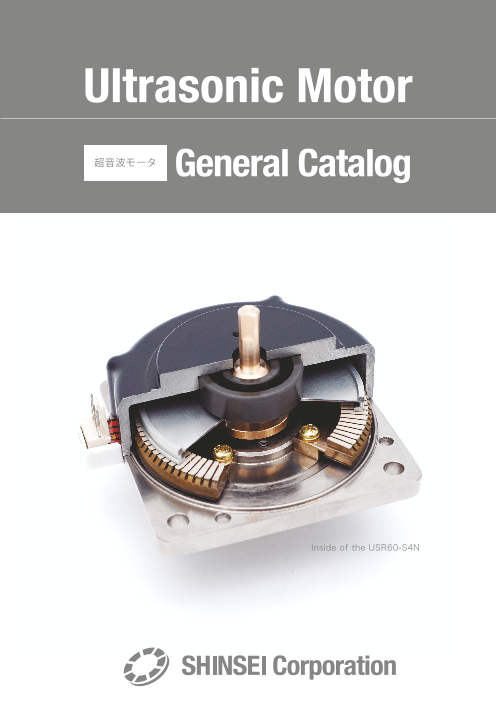
Inside of the USR60-S4N
Page2
About Ultrasonic Motor
What Is Ultrasonic Motor?
The ultrasonic motor does not use electromagnetic action, which is the driving principle of electromagnetic motor. It transforms back-and-forth motion
from elastic vibration on the ultrasonic band of the oscillating body into one-way motion with frictional force.It is the actuator that transports the
moving body.
Traveling Wave Direction Ultrasonic Motor
An oscillating body (stator) is structured by pasting together piezoelectric ceramic with an
Moving body elastic body, such as metal. It is set up by pressure contact moving body (rotor) on the Elastic body Direction of
movement direction oscillating body using spring or similar method. At that time, wear-proof friction material is
Friction material structured on the surface of the oscillating or moving body to reduce wear.
Vibrator Two sets of drive electrodes are formed on the piezoelectric ceramic and when prescribed Elliptical motion
Elastic body Direction of the traveling phase-difference AC voltage is applied, the traveling wave of flexural vibration is driven on an
wave movement oscillating body, and points on oscillating body surface travels in an elliptical orbit movement.
Piezoelectric ceramic The moving body comes into contact only at the wave crest of the traveling wave, and travels
in the opposite direction of the traveling wave due to friction drive.
Characteristics of Ultrasonic Motor
① Low speed, high torque High torque is obtained at a low speed allowing for direct drive of the motor.
② Self-holding Maintains high holding power even with the power off, requiring no electromagnetic brake to maintain position.
Possesses high responsivity and high controllability due to small moment of inertia of rotor and controlling
③ High responsivity, High controllability power due to motor friction.
④ Non-magnetic Not affected by magnets because frictional force is the driving principle, the equipment can be safely used in a high magnetic field environment of higher than 3[T].
⑤ Downsizing and Lightening Small and light because of its simple structure.
⑥ Quietness Compared to combination of general electromagnetic motor with decelerator, equipment operates with minimal noise of about 20[dB].
Example of Practical Use and Application of Ultrasonic Motor
The ultrasonic motor is used for the following applications making use of its features.
Responsivity Coarse andfine movement Hollowness Low noise Holding power High torque Non-magnetic
① Camera platforms, gimbals
② Stage rotating mechanism
③ Robot arm finger
④ Main body and peripheral equipment for MRI magnetic resonance imaging devices
⑤ Hands for surgical robots in MRI’ s
⑥ Surgical microscopes
⑦ Paleomagnetic measurement devices
⑧ Electronic microscope
2
Page3
Precautions
Precautions for Use
① Avoid putting excessive load or inertial load on the motor as much as possible.
Excess or inertial load may shorten motor life due to stator and rotor abrasion.
② Do not place thrust load on the output shaft of the motor.
Doing so may cause property degradation of the motor.
③ Do not place rotation force above the holding torque from outside when motor is stopped.
Doing so may damage the motor.
④ The motor output shaft has a g6 dimensional tolerance.
Avoid fitting with indentation or driving into a counter hole.
⑤ Ensure sufficient heat dissipation to hold motor case temperature to below 55 °C.
⑥ When using or storing the motor, ensure that humidity around the device is below 45%.
⑦ Motor is adjusted in the set of driver and cable.
Readjust driver when changing combination or cable length.
⑧ Use driver power source with sufficient power capacity.
The Field Ultrasonic Motor is Less Compatible
The ultrasonic motor has many advantages over the electromagnetic motor.Taking advantage of its merits, it is being used for many purposes.High
holding power is a merit when using the brake; however, it is a demerit when using during free state with power off.To ensure appropriate use of the
ultrasonic motor, below are examples of conditions under which the ultrasonic motor may show poor performance.
① Use under environments with high humidity oil corrosive gas dust In environments with humidity over 45 [%] may cause blocking.
② Extended continuous operation under adiabatic state Efficiency of the ultrasonic motor is approximately 30 [%]. The remainder will turn into
heat; and therefore, cooling is required for extended continuous operation.
③ Use requiring extended hours of endurance The ultrasonic motor rotates under the principle of friction drive; and therefore, durability
is shorter than an electromagnetic motor due to abrasion and damage to drive part.
④ Frequent start-stop motion under high inertial load state This will cause intense wear of lining material causing a shortening of the working life.
The ultrasonic motor operates under the pressure contact state of stator and rotor which
⑤ Use requiring ultra-precision rotation generates minute uneven rotation.
Uneven rotation when speed is controlled by encoder will be 0.1 [%] at 150 [rpm]
high-speed rotation and 0.5 [%] at 15 [rpm] low-speed rotation.
※ Note — Control at open loop
The ultrasonic motor operating principle is different from stepping motor. Therefore, accurate position control and speed control cannot be performed with open loop control.
Performing feedback control with rotary encoder, etc. is recommended for accurate control.
3
Page4
USR30 Series Motor
USR30-B3 USR30-B4
Drive Frequency 49KHz to 55KHz Drive Frequency 49KHz to 55KHz
Drive Voltage 110Vrms Drive Voltage 110Vrms
Rated Output 1.3W Rated Output 1.3W
Caseless Maximum Output 2.5W(by Maximum Load) Caseless Maximum Output 2.5W(by Maximum Load)
Rated Speed 250rpm Rated Speed 250rpm
Maximum Speed 300rpm Maximum Speed 300rpm
Rated Torque 0.05N・m(0.51Kgf・cm) Rated Torque 0.05N・m(0.51Kgf・cm)
Maximum Torque 0.1N・m(1.02Kgf・cm) Maximum Torque 0.1N・m(1.02Kgf・cm)
Holding Torque 0.1N・m(1.02Kgf・cm) Holding Torque 0.1N・m(1.02Kgf・cm)
Responsivity 1ms or less (No inertia load) Responsivity 1ms or less (No inertia load)
Direction of Rotation CW, CCW Direction of Rotation CW, CCW
Operating Temperature Range -10°C to +55°C Operating Temperature Range -10°C to +55°C
Operating Temperature Limit Stator surface 70°C Operating Temperature Limit Stator surface 70°C
Operating Humidity Range 0 to +45%(No condensation) Operating Humidity Range 0 to +45%(No condensation)
Size 30×40×25mm Size 30×40×44.5mm
Weight 17g Weight 19g
Remarks Single Shaft-Type Remarks Double Shaft-Type
Dimensional Drawing (Unit: mm) Dimensional Drawing (Unit: mm)
USR30-S3 USR30-S4
Drive Frequency 49KHz to 55KHz Drive Frequency 49KHz to 55KHz
Drive Voltage 110Vrms Drive Voltage 110Vrms
Rated Output 1.3W Rated Output 1.3W
Maximum Output 2.5W(by Maximum Load) Maximum Output 2.5W(by Maximum Load)
Rated Speed 250rpm Rated Speed 250rpm
Maximum Speed 300rpm Maximum Speed 300rpm
Rated Torque 0.05N・m(0.51Kgf・cm) Rated Torque 0.05N・m(0.51Kgf・cm)
Maximum Torque 0.1N・m(1.02Kgf・cm) Maximum Torque 0.1N・m(1.02Kgf・cm)
Holding Torque 0.1N・m(1.02Kgf・cm) Holding Torque 0.1N・m(1.02Kgf・cm)
Responsivity 1ms or less (No inertia load) Responsivity 1ms or less (No inertia load)
Direction of Rotation CW, CCW Direction of Rotation CW, CCW
Operating Temperature Range -10°C to +55°C Operating Temperature Range -10°C to +55°C
Operating Temperature Limit Case surface 60°C Operating Temperature Limit Case surface 60°C
Operating Humidity Range 0 to +45%(No condensation) Operating Humidity Range 0 to +45%(No condensation)
Size 36×44×30mm Size 36×44×44.5mm
Weight 43g Weight 45g
Remarks Single Shaft-Type Remarks Double Shaft-Type
Dimensional Drawing (Unit: mm) Dimensional Drawing (Unit: mm)
4
Page5
USR30 Series Motor
USR30-S3N USR30-S4N
Drive Frequency 49KHz to 55KHz Drive Frequency 49KHz to 55KHz
Drive Voltage 110Vrms Drive Voltage 110Vrms
Rated Output 1.0W Rated Output 1.0W
Non-magnetic Maximum Output 2.0W(by Maximum Load) Non-magnetic Maximum Output 2.0W(by Maximum Load)
Rated Speed 200rpm Rated Speed 200rpm
Maximum Speed 250rpm Maximum Speed 250rpm
Rated Torque 0.05N・m(0.51Kgf・cm) Rated Torque 0.05N・m(0.51Kgf・cm)
Maximum Torque 0.1N・m(1.02Kgf・cm) Maximum Torque 0.1N・m(1.02Kgf・cm)
Holding Torque 0.1N・m(1.02Kgf・cm) Holding Torque 0.1N・m(1.02Kgf・cm)
Responsivity 1ms or less (No inertia load) Responsivity 1ms or less (No inertia load)
Direction of Rotation CW, CCW Direction of Rotation CW, CCW
Operating Temperature Range -10°C to +55°C Operating Temperature Range -10°C to +55°C
Operating Temperature Limit Case surface 60°C Operating Temperature Limit Case surface 60°C
Operating Humidity Range 0 to +45%(No condensation) Operating Humidity Range 0 to +45%(No condensation)
Size 36×44×30mm Size 36×44×44.5mm
Weight 48g Weight 50g
Remarks Single Shaft-Type Remarks Double Shaft-Type
Dimensional Drawing (Unit: mm) Dimensional Drawing (Unit: mm)
USR30-E3 (500P/R) / USR30-E3T (1000P/R) USR30-E3N (500P/R) / USR30-E3NT (1000P/R)
Drive Frequency 49KHz to 55KHz Drive Frequency 49KHz to 55KHz
Drive Voltage 110Vrms Drive Voltage 110Vrms
Rated Output 1.3W Non-magnetic Rated Output 1.0W
Maximum Output 2.5W(by Maximum Load) Maximum Output 2.0W(by Maximum Load)
Rated Speed 250rpm Rated Speed 200rpm
Maximum Speed 300rpm Maximum Speed 250rpm
Rated Torque 0.05N・m(0.51Kgf・cm) With encoder Rated Torque 0.05N・m(0.51Kgf・cm)
Maximum Torque 0.1N・m(1.02Kgf・cm) Maximum Torque 0.1N・m(1.02Kgf・cm)
Holding Torque 0.1N・m(1.02Kgf・cm) Holding Torque 0.1N・m(1.02Kgf・cm)
Responsivity 1ms or less (No inertia load) Responsivity 1ms or less (No inertia load)
Direction of Rotation CW, CCW Direction of Rotation CW, CCW
Operating Temperature Range -10°C to +55°C Operating Temperature Range -10°C to +55°C
Operating Temperature Limit Case surface 60°C Operating Temperature Limit Case surface 60°C
Operating Humidity Range 0 to +45%(No condensation) Operating Humidity Range 0 to +45%(No condensation)
Size 36×50×48mm Size 36×50×48mm
Weight 64g Weight 69g
Remarks Encoder Resolution: 500P/R or 1000P/R Remarks Encoder Resolution: 500P/R or 1000P/R
Dimensional Drawing (Unit: mm) Dimensional Drawing (Unit: mm)
5
Page6
USR60 Series Motor
USR60-S3 USR60-S4
Drive Frequency 40KHz to 5KHz Drive Frequency 40KHz to 5KHz
Drive Voltage 130Vrms Drive Voltage 130Vrms
Rated Output 5.0W Rated Output 5.0W
Maximum Output 10.0W(by Maximum Load) Maximum Output 10.0W(by Maximum Load)
Rated Speed 100rpm Rated Speed 100rpm
Maximum Speed 150rpm Maximum Speed 150rpm
Rated Torque 0.5N・m(5.1Kgf・cm) Rated Torque 0.5N・m(5.1Kgf・cm)
Maximum Torque 1.0N・m(10.2Kgf・cm) Maximum Torque 1.0N・m(10.2Kgf・cm)
Holding Torque 1.0N・m(10.2Kgf・cm) Holding Torque 1.0N・m(10.2Kgf・cm)
Responsivity 1ms or less (No inertia load) Responsivity 1ms or less (No inertia load)
Direction of Rotation CW, CCW Direction of Rotation CW, CCW
Operating Temperature Range -10°C to +55°C Operating Temperature Range -10°C to +55°C
Operating Temperature Limit Case surface 60°C Operating Temperature Limit Case surface 60°C
Operating Humidity Range 0 to +45%(No condensation) Operating Humidity Range 0 to +45%(No condensation)
Size 67×77×47.5mm Size 67×77×60mm
Weight 258g Weight 261g
Remarks Single Shaft-Type Remarks Double Shaft-Type
Dimensional Drawing (Unit: mm) Dimensional Drawing (Unit: mm)
USR60-S3N USR60-S4N
Drive Frequency 40KHz to 45KHz Drive Frequency 40KHz to 45KHz
Drive Voltage 130Vrms Drive Voltage 130Vrms
Non-magnetic Rated Output 5.0W Non-magnetic Rated Output 5.0W
Maximum Output 10.0W(by Maximum Load) Maximum Output 10.0W(by Maximum Load)
Rated Speed 100rpm Rated Speed 100rpm
Maximum Speed 150rpm Maximum Speed 150rpm
Rated Torque 0.5N・m(5.1Kgf・cm) Rated Torque 0.5N・m(5.1Kgf・cm)
Maximum Torque 1.0N・m(10.2Kgf・cm) Maximum Torque 1.0N・m(10.2Kgf・cm)
Holding Torque 1.0N・m(10.2Kgf・cm) Holding Torque 1.0N・m(10.2Kgf・cm)
Responsivity 1ms or less (No inertia load) Responsivity 1ms or less (No inertia load)
Direction of Rotation CW, CCW Direction of Rotation CW, CCW
Operating Temperature Range -10°C to +55°C Operating Temperature Range -10°C to +55°C
Operating Temperature Limit Case surface 60°C Operating Temperature Limit Case surface 60°C
Operating Humidity Range 0 to +45%(No condensation) Operating Humidity Range 0 to +45%(No condensation)
Size 67×77×47.5mm Size 67×77×60mm
Weight 250g Weight 254g
Remarks Single Shaft-Type Remarks Double Shaft-Type
Dimensional Drawing (Unit: mm) Dimensional Drawing (Unit: mm)
6
Page7
USR60 Series Motor / Driver
USR60-E3 (500P/R) / USR60-E3T (1000P/R) USR60-E3N (500P/R) / USR60-E3NT (1000P/R)
Drive Frequency 40KHz to 45KHz Drive Frequency 40KHz to 45KHz
Drive Voltage 130Vrms Drive Voltage 130Vrms
Rated Output 5.0W Rated Output 5.0W
With encoder Non-magnetic
Maximum Output 10.0W(by Maximum Load) Maximum Output 10.0W(by Maximum Load)
Rated Speed 100rpm Rated Speed 100rpm
Maximum Speed 150rpm Maximum Speed 150rpm
Rated Torque 0.5N・m(5.1Kgf・cm) With encoder Rated Torque 0.5N・m(5.1Kgf・cm)
Maximum Torque 1.0N・m(10.2Kgf・cm) Maximum Torque 1.0N・m(10.2Kgf・cm)
Holding Torque 1.0N・m(10.2Kgf・cm) Holding Torque 1.0N・m(10.2Kgf・cm)
Responsivity 1ms or less (No inertia load) Responsivity 1ms or less (No inertia load)
Direction of Rotation CW, CCW Direction of Rotation CW, CCW
Operating Temperature Range -10°C to +55°C Operating Temperature Range -10°C to +55°C
Operating Temperature Limit Case surface 60°C Operating Temperature Limit Case surface 60°C
Operating Humidity Range 0 to +45%(No condensation) Operating Humidity Range 0 to +45%(No condensation)
Size 67×77×66mm Size 67×77×66mm
Weight 266g Weight 272g
Remarks Encoder Resolution: 500P/R or 1000P/R Remarks Encoder Resolution: 500P/R or 1000P/R
Dimensional Drawing (Unit: mm) Dimensional Drawing (Unit: mm)
D6030 D6060 / D6060E (With Speed Control Function)
Driver for Ultrasonic Motor USR30
Power Supply Voltage DC24V±0.5V (DC12V±0.5V) Power Supply Voltage DC24V±0.5V (DC12V±0.5V)
Oscillation Waveform Pseudo Sine Wave Oscillation Waveform Pseudo Sine Wave
Oscillation Frequency 47KHz to 52KHz Oscillation Frequency 48KHz to 55KHz
Speed transmission system Frequency Modulation 41KHz to 46KHz
Frequency Control Automatic Tracking System with Vibration Amplitude Feedback Speed transmission system Frequency Modulation
Motor Drive Voltage 110Vrms Frequency Control Automatic Tracking System with Vibration Amplitude Feedback
Current Consumption (Maximum) DC24V:0.8A / DC12V:1.5A Automatic Tracking with Encoder Signal Feedback
Overcurrent Protection 24V:0.8A (φ5.2 Midget Fuse) Motor Drive Voltage 110Vrms
12V:1.5A (φ5.2 Midget Fuse) Current Consumption (Maximum) DC24V:0.8A / DC12V:1.5A
Insulation Resistance 10MΩ or more (Unconnected Motor, Connection Between Case and Terminals) Overcurrent Protection 24V:0.8A (φ5.2 Midget Fuse)
Dielectric Withstand Voltage 1KVAC (Unconnected Motor, Connection Between Case and Terminals) 12V:1.5A (φ5.2 Midget Fuse)
Storage Temperature Range -20°C to +80°C (No Condensation) Insulation Resistance 10MΩ or more (Unconnected Motor, Connection Between Case and Terminals)
Operating Temperature Limit -10°C to +55°C (No Condensation) Dielectric Withstand Voltage 1KVAC (Unconnected Motor, Connection Between Case and Terminals)
Start/Stop Operation TTL Level Signal Switching (Prepare separately when using switch) Storage Temperature Range -20°C to +80 (No Condensation)
Start-Up Response 50ms or less (No motor inertia load) Operating Temperature Limit -10°C to +55°C (No Condensation)
Stop Response 1ms or less (No motor inertia load) Start/Stop Operation TTL Level Signal Switching (Prepare separately when using switch)
No-load Variable Speed Range 30rpm to 300rpm Start-Up Response 50ms or less (No motor inertia load)
Speed Adjustment External Voltage DC0V to 3.2V Stop Response 1ms or less (No motor inertia load)
Recommended Start/Stop Switch Single-Pole/Double-Throw Switch with Center (ON-OFF-ON) No-load Variable Speed Range 20rpm to 150rpm (D6060)
Recommended speed setting volume 10KΩ, 0.1W, Type B (Must be prepared separately) 15rpm to 150rpm (D6060E)
Weight 105g Speed Adjustment External Voltage DC0V to 3.2V
Size 22×70×56mm Recommended Start/Stop Switch Single-Pole/Double-Throw Switch with Center (ON-OFF-ON)
Recommended speed setting volume 10KΩ, 0.1W, Type B (Must be prepared separately)
Weight 250g (D6060) / 260g (D6060E)
Size 35×100×83mm
7
Page8
Each Part Names of and Connection Diagram for D6030 Driver
Name and Function of Each Part for D6030
Maximum RPM setting volume (VR2) LED indicator (Red)
No load speed is set at 300 [rpm]. Lights when the power is ON.It will not light when the internal fuse has blown.
Motor Connection Terminal Connector to 24[V] power,
start-stop switch and speed set volume knob
Refer to the basic connection diagram for the function of each pin.
Balance Adjustment Volume (VR3) Minimum Rotational Speed Setting Volume (VR1)
This volume knob adjusts rotational difference of CW and CCW. No load speed is set at 30 [rpm].
※ Rotation speed is adjusted. Do not change under normal operation.
Basic Connection Diagram for D6030
○ Precautions with Connection
1. Always use the cable provided for the connection of motor and driver.
1 black GND
2 N.C. red Sin Readjustment of driver is necessary when changing the length of the
3 red Sin black GND
4 white Cos yellow F.B. cab le . Refer to page 12 fo r how to ad jus t the d r i ver fo r the
5 yellow F.B. white Cos readjustment method.
*Black is shield wire.
1 black 24V
2 red ※To change the length of the cable after purchase, we ask that you
3 light blue send the motor, driver and motor cable for readjustment. Please
4 brown OFF CW5 purple CCW carefully consider the length of cable when purchasing.6 blue
7 yellow
8 white
10KΩ 2. Shortening the motor cable will blow the fuse to protect the interior.
Please note that connecting erroneously, may damage the inner
semiconductor.
※Speed setting and switching over from start and stop can be done with the volume knob and switch shown on the diagram, as well as
with non-contact point (TTL, transistor). Refer to pages 13 and 14 for external control for details. 3. To extend cable for signal, ensure sufficient margin for voltage value
and use shield line to prevent noise.
How to Connect to USR30-B3/B4※
Mounting plate (metal with conductivity)
Connection to terminal ※The driver power side of the motor cable is connected with a connector; however,
on the motor side, it must be connected directly by soldering.
Soldering cable to terminal
In such case,
solder ③ sin red, ④ cos white and ⑤ F.B yellow
on the designated position of the FPC input area,
red white
(Sin-signal) (Cos-signal) and connect ① GND shield line somewhere on the metallic case
GND line (line bundling shield lines) yellow with conduction attained with motor installation surface. (F.B.-signal)
8
Page9
External Control Method for D6030
Inner Circuit of D6030
CN1
Output transformer
1 black
2
red sin Motor Stabilized voltage of +3.2 [V] Max. 5 [mA] is output to3
white cos the common terminal ③ light blue and speed setting volume terminal ⑥ blue4
5 yellow F.B. on the start-stop switch.
DC24V
black DC24V
Regulator 1 CW and CCW start/stop for
2 red
Vref 3.2V light blue rotation command terminal ④ brown and ⑤ purple3
11kΩ Zi CW brown turn ON at TTL input level of Hi+2.5 to +5.5[V] and turn OFF at Lo0 to +0.4[V].4
5.5kΩ Zi CCW
5 purple Start/Stop
blue ※Impedance for ④ brown is 11 [KΩ] and impedance for ⑤ purple is 5.5 [KΩ].Dedicated IC 6
7 yellow Speed setting
8 white
10kΩ CN2
Speed Control by External Voltage
To control speed with external voltage, connect DC variable voltage power as a
C N 2 substitute for volume between terminals ⑦ yellow and ⑧ white.
6 N C
Changing the voltage to 0 to 3.2[V] enables speed control equivalent to changing
7 y e l l o w
Driver Side volume to 0 to max. Consumption current is below 0.5[mA] and impedance is over
+ DC 0 to 3.2[V] 10[KΩ] for external voltage source.
Adjustable power supply
w h i t e (0.3 [mA])8 There is a restriction on the change rate of rise for speed command voltage.
Refer to the Timing Chart on page 12.
Start, Stop and Rotation Direction Switching by External Signal
3 light blue
1kΩ
+3.2V OFF +3.2V 3 light blue
ON OFF
CW 4 brown brown1kΩ CW 4 ON
OFF
CCW 5 purple purple
OFF
ON CCW 5
ON
+3.2V 3 light blue
ON
4 brown
OFF
CW
ON
purple
CCW 5 OFF
9
Page10
Each Part Names of and Connection Diagram for D6060/D6060E Driver
Name and Function of Each Part for D6060/D6060E
※ Controller connector and encoder connector are D6060E only.
Encoder Connector (*only D6060E) ※ Rotation speed is adjusted. Do not change under normal operation.
This enables speed control using encoder signal, and use of
controller enables position control.
Controller Connector (*only D6060E)
This is the terminal for encoder signal through output and motor
control signal input and output. Black Motor Connection TerminalGND
Connecting this terminal with the controller enables control of Connect by matching the color of cables.Red
sin
speed and position of the motor. When using this terminal, leave
White
terminals ③ to ⑧ as N.C.. cos
O.L.6 is an open collector. ( L: normal / H: overload ) YellowF.B Speed Setting Volume Connecting Terminal
3
Speed can be set with B10 [KΩ] (0.1 [W]) rheostat.
Minimum Rotational Speed Setting Volume 21
No load speed is set at 20 [rpm] (D6060E set at 15 [rpm]). Start-stop Switch
GND In the case of contact, use the snap switch (for minute
CCW c u r r e n t ) w i t h O F F s w i t c h f o r S i n g l e - P o l e /
Maximum Rotational Speed Setting Volume Double-Throw Center.
No load speed is set at 150 [rpm]. CW
+
Balance Adjustment Volume Power Connection Terminal
Volume knob for adjustment of CW and CCW rotational This terminal connects with DC 24[V] power source.
speed difference. (Adjustment not required for D6060E)
LED indicator (Red) LED indicator (Green)
Lights up when motor is overloaded and stops the motor. Lights when the power is ON.
To reset, turn OFF the power or start switch, eliminate It will not light when the internal fuse has blown.
cause and reboot.
Basic Connection Diagram for D6060/D6060E
Shield Connect to motor
Phase Z
※To control using encoder signal, connect encoder
cable to this connector. Phase B black GND
Connector pin arrangement is as shown in the Phase A BlackGND ⑫
diagram on the left. +5V Red red Sin
sin ⑪
GND White
cos ⑩
white Cos
Molex 5045-06A Yellow ⑨ yellow F.B.F.B
3 ⑧
Hi
⑦ Speed setting
2 Lo volume
Use this connector to control sequence with 1 ⑥
control ler. Connector pin arrangement is as ★ GND (1) GND ⑤
shown in the diagram on the left. (6)O.L.★ CW (2) CCW
Encoder output is 5 [V] voltage output. (7)GND CCW ④
★ CCW (3) Start-Stop(★mark is common with connection terminal) (8) OFFPhase B CW switch
★ Transmission(4) ③
(9)Phase Z CW
Phase A (5) + ② + Power input
- DC24V
※(6) O.L. is H: Overload, L: Normal D-sub 9pin (female)
①
(For sink current Max. 20 [mA], output is open connector.)
10
POWER OVER SPEED SPEEDBAL MAX ControllerLOAD Encorder
-
POWER OVER SPEED SPEED
LOAD BAL MAX
Controller Encorder
-
Page11
External Control Method of D6060/D6060E
Inner Circuit of D6060/D6060E
+ 3.2V voltage source 8 +3.2V Reference voltage ( 2mA max )
7 Speed control( 0 to 3.2V / 0.3mA max ) Stabilized voltage of +3.2 [V] (Max2 [mA]) is output to
6 GND the speed setting volume terminal ⑧ blue.
10kΩ
5 GND
CW and CCW start/stop for rotation command terminal ④ and ⑤
4 CCW turns OFF at Hi(2.5 – 5.5 [V]) and turns ON at Lo(0 – 0.4 [V]) of TTL input level.
3 CW ※Impedance for current value 2.3 [mA], ③ and ④ is 2.2 [KΩ].
+5V
2.2kΩ
Speed Control by External Voltage
To control speed with external voltage, connect DC variable voltage power as
8 N C substitute for volume between terminals ⑥ and ⑦.
Changing the voltage to 0 to 3.2 [V] enables speed control equivalent to changing
7 volume to between 0 to max.
Driver Side
+ DC 0 to 3.2[V]
Variable power supply ※Consumption current is below 0.5 [mA] for external voltage source.
(0.3 [mA] or more)
6 ※There is a restriction on the change rate of rise for speed command voltage.
Refer to the Timing Chart on page 12.
Start, Stop and Rotation Direction Switching by External Signal
In the case of relay In the case of TTL
5 5
When CW and CCW are turned ON simultaneously, CW takes precedence.
4 4 Refer to Timing Chart on page 12 for switchover interval.
3 3
#7405 etc.
Speed control by encoder (*only D6060E)
For uses requiring minute speed control, speed control using encoder with D6060E will be effective.
Speed error value within normal use range is 0.1 to 0.5 [%].
Servo System with Encoder and Controller (*Only D6060E)
Driver voltage (130Vrms) Simultaneous position and speed control (servo system) are possible with
encoder signal and controller. It is possible to determine position and variable
Encoder signal
D6060E speed control in bulk with PC program, and it is also possible to automatically
Computer Controller Driver DC24V Motor operate with program stored in controller.
11
Page12
Other Matters Regarding Driver
Driver Circuit Configuration
DC 24V
Regulator Power amplifier Motor
0V Output
transformer Sin ・ Driver case has not been dropped to GND electrical potential.
Distributor
Output Cos ・ Motor case is connected to GND (shield line) and dropped to GND electrical transformer
GND potential of power input (24VDC).
CW CCW F.B.
Oscillator Speed setting
Error amplifier
Timing Chart
ON
Power supply OFF ① Time required from driver power ON to start command (CW or CCW) ON is more than 100ms 10ms
CW rotation command ① ② 100 [ms].
② More than a 10 [ms] interval time is required to switchover forward and reverse rotation.
CCW rotation command ③ ③
50ms 50ms ③ Start-up response (when no inertial load) takes approximately 50[ms]. ④
Motor movement CW rotation 1ms ④ Stop response (when no inertial load) takes less than 1 [ms].
⑤ 0.065V/msec ④ CCW rotation ⑤ Reclosing after motor stops due to overload requires about a 10 [s] interval after turning
External speed 10ms 1ms
command voltage Max 3.2V OFF the power. (*Excluding D6030)
0V
How to Adjust the Driver
Motor and driver are set at optimal state matching the specification at the time of shipment.Therefore, as a rule, driver adjustment should not be
performed by user. (*Malfunction from adjustment made by user is not covered by warranty. Request for readjustment will be charged.)
If for some reason there is a need for adjustment, follow the directions below.
W h a t Y o u N e e d
Frequency meter (Input voltage: higher than 150 [Vrms]) / Ammeter (Capacity: 5 [A]) / Tachometer (Non-contact type is desirable) / Small Phillips screwdriver
1. Connect frequency meter between GND and Sin (or Cos) of motor cable. (Caution: High voltage. Exercise care in handling measuring instrument)
2. Create no-load state for motor to enable measurement with tachometer.
3. Adjustment of Minimum Rotational Speed
When CW/CCW rotation command is made at minimal for external speed setting volume or with 0 [V] outer speed command voltage, adjust the minimum rotation setting volume
(turning clockwise increases the rotation speed) to set at 15 or 20 [rpm] for D6060 and D6060E (USR60 series), or 30 [rpm] for D6060E and D6030 (USR30 series).
Check that frequency range is 41 to 44 [KHz] for USR60 series and 51 to 52 [KHz] for USR30 series.
4. Adjustment of Maximum Rotational Speed
When CW/CCW rotation command is at maximum for external speed setting volume or with 3.2 [V] outer speed command voltage, adjust the maximum rotation setting volume
(turning clockwise increases the rotation speed) to set at 150 [rpm] for USR60 series and 300 [rpm] for USR 30 series.
Check that frequency range is around 40[ KHz] for USR 60 series and around 50 [KHz] for USR 30 series.
5. Balance Correction (Correction of unbalanced CW/CCW rotation)
Make adjustment with balance adjustment volume to ensure the same rotation for CW and CCW with the maximum rotation adjustment.
Maximum rotation will change. Repeat steps 4 and 5 several times to make maximum rotation the same for CW and CCW.
(Balance correction not required for D6060E)
※ Why is readjustment of driver no longer necessary?
Increase and decrease in electric resistance when changing the length of motor cable connecting motor and driver, for example, will change the feedback signal. Feedback signal is for the measurement of stator vibration amplitude from
the driver side by output of voltage from monitor electrode. Therefore, if the electric resistance increases or decreases during that time, the feedback signal voltage will also change, interfering with driver’ s appropriate frequency
oscillation leading to abnormal rotation. Readjustment of driver is necessary to set the rotation speed to the proper value.
When the length of the motor cable is changed significantly (change of more than 5[m]), impedance between motor and driver increases or decreases, reactive current increases and potentially damaging driver by overheating.
In such case, measures such as adding coil to driver to adjust impedance will be required.
12
Page13
Diagram
& Specifications
Shaft
Cover
Bearing
Rotor
Sliding Material
Stator
Piezoelectric ceramic
Page14
Diagram
USR30-B3
USR30-B4
14
Page15
Diagram
USR30-S3 / USR30-S3N
USR30-S4 / USR30-S4N
USR30-E3 / USR30-E3T / USR30-E3N / USR30-E3NT
15
Page16
Diagram
USR60-S3 / USR60-S3N
USR60-S4 / USR60-S4N
USR60-E3 / USR60-E3T / USR60-E3N / USR60-E3NT
16
Page17
Diagram
D6030
D6060 / D6060E
17
Page18
List of Specifications
USR30 series
Model USR30-B3 USR30-B4 USR30-S3 USR30-S4 USR30-E3 USR30-E3T USR30-S3N USR30-S4N USR30-E3N USR60-E3NT
Drive Frequency 49KHz to 55KHz
Drive Voltage 110Vrms
Rated Output 1.3W 1.0W
Maximum Output 2.5W (by Maximum Load) 2.0W (by Maximum Load)
Rated Speed 250rpm 200rpm
Maximum Speed 300rpm 250rpm
Rated Torque 0.05N・m (0.51Kgf・cm)
Maximum Torque 0.1N・m (1.02Kgf・cm)
Holding Torque 0.1N・m (1.02Kgf・cm)
Responsivity 1ms or less (No inertia load)
Direction of Rotation: CW, CCW
Operating Temperature Range: -10°C to +55°C
Operating Temperature Limit: Stator surface 70°C, Case surface 60°C
Operating Humidity Range: 0 to +45% (No condensation)
Size 30×40×25mm 30×40×44.5mm 36×44×30mm 36×44×44.5mm 36×50×48mm 36×50×48mm 36×44×30mm 36×44×44.5mm 36×50×48mm 36×50×48mm
Weight 17g 19g 43g 45g 64g 64g 48g 50g 69g 69g
Remarks Single Shaft-Type Double Shaft-Type Single Shaft-Type Double Shaft-Type Encoder Resolution: 500P/R Encoder Resolution: 1000P/R Single Shaft-Type Double Shaft-Type Encoder Resolution: 500P/R Encoder Resolution: 1000P/R
Features and Range of Use
300 300
250 250
200 200
Range of Ordinary Use 100 100
60 60
Range of Short Time Use (rpm) 30 (rpm) 30
0 0.02 0.04 0.06 0.08 0.1 0 0.02 0.04 0.06 0.08 0.1
Torque(N・m) Torque(N・m)
USR60 series
Model USR60-S3 USR60-S4 USR60-E3 USR60-E3T USR60-S3N USR60-S4N USR60-E3N USR60-E3NT
Drive Frequency 40KHz to 45KHz
Drive Voltage 130Vrms
Rated Output 5.0W
Maximum Output 10.0W (by Maximum Load)
Rated Speed 100rpm
Maximum Speed 150rpm
Rated Torque 0.5N・m (5.1Kgf・cm)
Maximum Torque 1.0N・m (10.2Kgf・cm)
Holding Torque 1.0N・m (10.2Kgf・cm)
Responsivity 1ms or less (No inertia load)
Direction of Rotation: CW, CCW
Operating Temperature Range: -10°C to +55°C
Operating Temperature Limit: Case surface 60°C
Operating Humidity Range: 0 to +45% (No condensation)
Size 67×77×47.5mm 67×774×60mm 67×77×66mm 67×77×66mm 67×77×47.5mm 67×77×60mm 67×77×66mm 67×77×66mm
Weight 258g 261g 266g 266g 250g 254g 272g 272g
Remarks Single Shaft-Type Double Shaft-Type Encoder Resolution: 500P/R Encoder Resolution: 1000P/R Single Shaft-Type Double Shaft-Type Encoder Resolution: 500P/R Encoder Resolution: 1000P/R
Features and Range of Use 160
140
120
100
80
60
Range of Ordinary Use 40
Range of Short Time Use (rpm) 20
0 0.2 0.4 0.6 0.8 1.0
Torque(N・m)
18
Rotational Speed
Rotational Speed
Rotational Speed
Page19
List of Specifications
Driver ※12V specifications for each model are optional
Model D6030 (24V) / D6030 (12V)※ D6060 (24V) / D6060 (12V)※ D6060E (24V) / D6060E (12V)※
Power Supply Voltage DC24V±0.5V / DC12V±0.5V
Oscillation Waveform Pseudo Sine Wave
Oscillation Frequency 47KHz to 52KHz 48KHz to 55KHz (USR30 series) / 41KHz to 46KHz (USR60 series)
Speed transmission system Frequency Modulation
Frequency Control Automatic Tracking System with Vibration Amplitude Feedback Automatic Tracking with Encoder Signal Feedback
Motor Drive Voltage 110Vrms 130Vrms
Current Consumption (Maximum) DC24V : 0.8A / DC12V : 0.5A DC24V : 2.5A / DC12V : 4.0A
Overcurrent Protection DC24V:0.8A (φ5.2 Midget Fuse) DC24V:2.5A (φ5.2 Midget Fuse)
/ DC12V:1.5A (φ5.2 Midget Fuse) / DC12V:4.0A (φ5.2 Midget Fuse)
Insulation Resistance 10 MΩ or more (Unconnected Motor, Connection Between Case and Terminals)
Dielectric Withstand Voltage 1KVAV (Unconnected Motor, Connection Between Case and Terminals)
Storage Temperature Range -20°C to +80°C (No Condensation)
Operating Temperature Limit -10°C to+55°C (No Condensation)
Start/Stop Operation TTL Level Signal Switching (Prepare separately when using switch)
Start-Up Response 50ms or less (No motor inertia load)
Stop Response 1ms or less (No motor inertia load)
No-load Variable Speed Range 30rpm to 300rpm 20rpm to 150rpm 15rpm to 150rpm
Speed Adjustment External Voltage DC 0V to 3.2V
Recommended Start/Stop Switch Single-Pole/Double-Throw Switch with Center (ON-OFF-ON)
Recommended speed setting volume 10KΩ, 0.1W, Type B(Must be prepared separately)
Size 22×70×56mm 35×100×83mm
Weight 105g 250g 260g
Remarks Equipped with speed control function using encoder signal
Encoder
Power-supply voltage DC5V±10%
Current consumption 85 mA or less
Detection method Optical incremental
Number of pulses 500P/R 1,000P/R
Output form Voltage
Output phase A, B, Z(I)
Output voltage H 2.4V DC or more
Output voltage L 0.4V DC or more
Output Circuit Power supply + 5 V
Output(A,B,Z)
GND
Signal Waveform Phase A
Phase B
Phase Z
(ex. CW)
Encoder Cable
(for D6060E)
Motor side (5P) white Phase B Driver side (6P)
red Power supply +5V
blue/green Phase A
yellow Phase Z
(for D6060) black Common 0VShielded wire
19
Page20
Company Profile
Company Profile
Company Name SHINSEI Corporation
Location 2-1-8 Kasuya, Setagaya-ku, Tokyo, 157-0063 Japan
Business Hours Mon-Fri: 10: 00-18: 00, Sat-Sun: holiday
Contact Phone: +81-3-3302-7677 (main)
FAX: +81-3-3329-0066
URL: http://www.shinsei-motor.com
Established March, 1968.
Capital 10 million yen
President Norio Sashida
Major Clients Universities and various research institutes (domestic and overseas), MRI and medical equipment manufacturer (domestic and overseas) etc.
Business Contents Manufacture, sales and development of Ultrasonic motor
Corporate History
1968 Shinsei Corporation is founded as a lapping machine manufacturer
1975 Head office transferred to Kasuya, Setagaya-Ku, Tokyo (current location)
Research and development of ultrasonic motor commences
1978 Founder Toshiiku Sashida announces the world’ s first “Wedge type Ultrasonic Motor”
1982 Research and development of practical use ultrasonic motor commences
1985 World’ s first “Rotation Type Ultrasonic Motor” driven by traveling wave announced
Development of rotation-type ultrasonic motor for commercialization commences
1999 Rotation-type ultrasonic Motor “USR30 Series” and “USR60 Series” commercialized
2010 Manufacturing of non-magnetic ultrasonic motor for MRI injector commences
Lineup of ultrasonic motor with the increase in name value expanded
2015 High-power electrostatic motor announced
Access
By Train
Take the Keio Line from Shinjuku Station and disembark at Hachiman-yama Station
(Local or Rapid). Approximately 10-minute walk in the direction of Roka Koshunen (not
toward Roka Koen Station).
By Car
Shinsei Corporation building is located on the Yahatayama Sanchome intersection along
Kanjo Road 8. It takes about 40 minutes from Shinjuku Station via Koshu Kaido.
※Parking spaces for three vehicles available. If there is no vacancy, make use of the
coin-operated parking in Roka Koshunen