


SmartMotors
Document Information
| Document Title | MoogAnimatics 2016 ProductCatalog |
|---|---|
| Document Type | Product Catalog |
| File size | 6.7Mb |
| Category | |
| Company | トーアメック株式会社 (Documents List) |

Document Contents
Page1
When Performance Really Matters®
Page2
Welcome to Moog Animatics
Thank you for your interest in our innovative automation solutions. Since its founding in 1987, Moog Animatics has delivered upon a
unique approach to motion and machine control that enables you to leapfrog your global competition. Moog Animatics is the world leader
in fully integrated servo technology and is part of Moog Inc., a worldwide designer, manufacturer, and integrator of precision motion control
products and systems. Moog’s high-performance systems control military and commercial aircraft, satellites and space vehicles, launch
vehicles, missiles, industrial machinery, wind energy, marine applications, and medical equipment.
Moog Animatics offers the most advanced highly integrated automation solutions in the industry. Starting with the SmartMotor™, the
world’s first fully integrated servo system, and extending through a large variety of I/O, machine control, software, and integrated actuator
products, Moog Animatics offers total solutions with a much smaller footprint, a lower total cost and a simplicity that reduces your machine
development and build time – getting you to market faster.
With offices in Tokyo, California, New York, Pennsylvania and Continental Europe, the sun never sets on Moog Animatics while we directly
support key customers along with a global network of factory trained Automation Solution Providers; independent companies in your
backyard ready to supply and support your Moog Animatics products through the long haul.
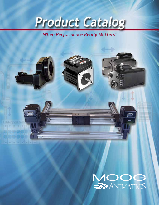
This catalog contains all Class 5 and Class 6 SmartMotor products, software, and Moog Animatics’ actuator line (Linear Integrated
Systems). All of the SmartMotor servos in this catalog have the latest feature set and are recommended for new designs.
Many new products are highlighted in this catalog, including our Class 6 EtherNet/IP™ SmartMotor that is available in both standard servo
and hybrid versions. The new product represents the next step in the evolution of the Class 6 integrated motor design, which includes
PROFINET® and EtherCAT® versions, and extends the robust, dual-port industrial Ethernet SmartMotor with EtherNet/IP™ Position
Controller capability.
Our expanded linear actuator offerings include low-backlash, high-precision, belt-driven rotary stage units, true belt-driven linear systems,
and combination H-Bot and T-Bot units for high-precision, two-axis motion. All units come integrated with your choice of SmartMotor.
Our exciting firmware advances include I/O device CAN Bus Master capability, sophisticated custom spooling pattern capabilities for
traverse and take-up winding applications, and DMX Protocol for a wide variety of entertainment automation applications.
In need of a custom solution for your motion control challenge? Please contact us and let us show you innovative, compact, and highly
effective ideas that are optimally engineered to help you gain competitive advantage and win in your market.
Thank you again and welcome to Moog Animatics, When Performance Really Matters®.
We define the future of motion control by innovation, invention, We invite our customers and users to join with us in the joint
and a dedication to the highest standards of professionalism and development of custom products and systems using our
quality in everything we do and in every product that we make. technology.
We invite quality firms to ally with us and to participate in our We commit to providing a fair workplace for our employees.
inventions and innovations for the benefit of the companies that We subscribe to the principle of being a good corporate citizen,
need and use our advanced technology and products. a good neighbor, and a protector of our environment.
When Performance Really Matters®
REVISED 01/17
2 Moog Animatics • www.animatics.com
Power Supplies Gearheads Actuators Cables, Etc. C6 Low Cost C6 M-Style C5 M-Style C5 D-Style Software Overview
Page3
Contents
Overview
New from Moog Animatics......................................................................................................................................................... 4
I/O Device CAN Bus Master and Combitronic™ Communications ............................................................................................. 5
Software
Software .................................................................................................................................................................................... 6
Class 5 D-Style
Class 5 Overview ...................................................................................................................................................................... 8
D-Style Motor — Understanding Part Numbers ........................................................................................................................ 9
D-Style Motor Comparison Chart ............................................................................................................................................ 10
D-Style Motor Torque Curves .................................................................................................................................................. 12
D-Style Motor CAD Drawings .................................................................................................................................................. 14
Class 5 D-Style Connector Pinouts ......................................................................................................................................... 16
Fieldbus Protocol Options ....................................................................................................................................................... 17
CDS Option and Recommended DE Option ........................................................................................................................... 18
Class 5 M-Style
Industrial M-Style SmartMotor with Optional IP-Rating ........................................................................................................... 19
Class 5 M-Style Motor Comparison Chart ............................................................................................................................... 20
M-Style Torque Curves and Motor CAD Drawings .................................................................................................................. 21
M-Style Connector Pinouts...................................................................................................................................................... 22
Class 6 M-Style
Class 6 Industrial Ethernet ...................................................................................................................................................... 23
Class 6 Specifications ............................................................................................................................................................. 24
Class 6 Torque Curves ............................................................................................................................................................ 25
Class 6 Drawings .................................................................................................................................................................... 26
Class 6 M-Style Connector Pinouts......................................................................................................................................... 27
Class 6 Low-Cost
Low-Cost 17 Frame — SL17406D .......................................................................................................................................... 28
Cables and Peripherals
Cables and Accessories .......................................................................................................................................................... 30
Boards and Test Interfaces ...................................................................................................................................................... 32
Actuators
Linear Actuators Overview ...................................................................................................................................................... 33
Linear Actuators — Understanding Part Numbers .................................................................................................................. 34
Linear Actuator Comparison Chart .......................................................................................................................................... 35
Belt-Driven Linear Actuators — PSC....................................................................................................................................... 37
Belt-Driven Linear Actuators — M6S....................................................................................................................................... 38
Rotary Actuators — ROT1 ......................................................................................................................................................... 39
Horizontal Two-Axis Gantry System — HBOT1 ............................................................................................................................ 40
Gearheads
Introduction to Gearheads ....................................................................................................................................................... 41
Planetary Gearheads — NEMA 17 Series .............................................................................................................................. 42
Planetary Gearheads — NEMA 23 Series .............................................................................................................................. 43
Planetary Gearheads — NEMA 34 Series .............................................................................................................................. 44
Right Angle Planetary Gearheads ........................................................................................................................................... 45
Power Supplies and Shunts
How to Choose Power Supplies .............................................................................................................................................. 46
Open Frame Linear Unregulated DC Power Supplies ............................................................................................................ 47
Enclosed Switch Mode DC Power Supply............................................................................................................................... 48
Enclosed DC Power Supplies ................................................................................................................................................ 49
Introduction to Shunts ............................................................................................................................................................ 50
Open Frame and Enclosed Shunts ......................................................................................................................................... 51
Notice: All SmartMotor™, actuator and product specifications are subject to change without notice.
Consult website or factory for latest data.
Declaration of Conformity (www.animatics.com/conformity)
Warranty Statement (www.animatics.com/warranty)
Technical Support: 888-356-0357
Moog Animatics • www.animatics.com 3
Overview Software C5 D-Style C5 M-Style C6 M-Style C6 Low-Cost Cables, Etc. Actuators Gearheads Power Supplies
Page4
Overview、New from Moog Animatics
NENWe!w from Moog Animatics
Class 6 Industrial Ethernet SmartMotors
Support EtherNet/IP™, PROFINET® and EtherCAT® protocols
• NEMA 23 frame in standard (MT) and high pole count (MH) versions
• High-end, high-speed processor for exceptional performance
• Compact, feature-rich controls allow for rapid solution development
See page 23 for details.
Low-Cost 17 Frame SmartMotor
SmartMotor features in a low-cost 17 frame package
• RS-232 and CANopen interfaces are standard
• Includes high-speed processor and Combitronic support
• Integrated drive and controller simplifies installation and reduced cost
See page 28 for details.
M6S/PSC Linear and ROT1 Rotary Actuators
SmartMotor-powered belt-driven actuators
• Delivered as a turnkey solution
• Low backlash, high positional accuracy and long service life
• Motor mounting options for maximum design and mounting flexibility
See pages 37-39 for details.
T-Bot and H-Bot Systems
SmartMotor-powered turnkey gantry systems
• Low backlash belt actuators with stationary SmartMotors
• Shipped preassembled with the SmartMotors of your choice
• Precise and accurate horizontal or vertical positioning for low to medium loads
See page 40 for details.
I/O Device CAN Bus Master ® Motor to I/O TM Motor to Motor Without data collision!
Interfaces with standard CiA 301 CANopen devices
• Multiple SmartMotors and multiple I/O devices on the same CAN bus
• Support for both PDO and SDO protocols (some limitations apply)
• SmartMotor achieves FULL machine control -- no other HMI or bus master required!
CANopen Valve Block
See page 5 for details. CANopenREMOTE I/O
CANopen
ABS Encoder
Expanded Traverse and Takeup Be sure to follow proper guidelines for CAN bus cabling and termination.
Now supports complex winding patterns
• Overlay camming profiles onto traversing profiles for complex patterns
• Prevent material from becoming tangled or trapped when unwinding
• Auto Reverse and Electronic Gearing profiles for the perfect spool every time
See website Case Studies and SmartMotor Developer’s Guide for details.
REVISED 01/17
4 Moog Animatics • www.animatics.com
Power Supplies Gearheads Actuators Cables, Etc. C6 Low-Cost C6 M-Style C5 M-Style C5 D-Style Software OOvveerrvviieeww
Page5
I/O Device CAN Bus Master and Combitronic™ Communications
I/O Device CAN Bus Master and Combitronic™ Communications
!
NEW
Motor to I/O TM® Motor to Motor Without data collision!
CANopen Valve Block
CANopen
REMOTE I/O
CANopen
ABS Encoder
Be sure to follow proper guidelines for CAN bus cabling and termination.
Be sure to follow proper guidelines for CAN bus cabling and termination.
I/O Device CAN Bus Master - SmartMotors can now interface with standard CiA 301 CANopen devices including but not
limited to:
• Remote digital/analog/mixed signal I/O • Temperature controllers
• CAN bus absolute or relative encoders • Pneumatic valve blocks
• Inclinometers • And more
• Load cells
Basic control allows 8, 16, or 32-bit sized data objects with support for both PDO and SDO protocols. The supported profiles include but
are not limited to I/O profile, encoder profile, and DS4xx profile. This provides the ability to:
• Dynamically map SmartMotor PDOs, map another device’s PDOs, start the NMT state
• A SmartMotor can send/receive up to 5 PDOs each for RX (Receive) and TX (Transmit)
• Read/write SDOs in expedited mode only; which works up to 32-bit data
Multiple SmartMotors and multiple I/O devices may be on the same CAN bus. This combined with Combitronic motor-to-motor
communications allows for complex, multi-axis, multi-I/O-device network control. Now you can achieve full machine control with just
the SmartMotors -- no other HMI or bus master is required!
TM High-Speed Communications is a protocol that operates over a standard “CAN” (Controller Area Network) interface.
It may simultaneously coexist with either CANopen or DeviceNet protocols. Unlike these common protocols however, Combitronic™
requires no single dedicated master to operate. Each integrated servo connected to the same network communicates on an equal
footing, sharing all information, and therefore, sharing all processing resources.
Combitronic protocol features:
• 120 axis node count
• 1 MHz bandwidth
• No master required
• No scan list or node list set up required
• All nodes have full read/write access to all other nodes
Combitronic™ technology allows any motor’s program to read from, write to, or control any other motor simply by tagging a local variable
or command with the other motor’s CAN address. All SmartMotors become one multi-tasking, data-sharing system without writing a single
line of communications code or requiring detailed knowledge of the CAN protocol. The only prerequisite is to have matched baud rates
and unique addresses.
For more details, see animatics.com/combi
Combitronic technology enables standalone multi-axis linear interpolation:
a=1 b=2 c=3 ' Motor addresses, x, y and z
x=123000 'X Axis Target Position
y=20000 'Y Axis Target Position
z=8000 'Z Axis Target Position
PTS(x;a,y;b,z;c) 'Set 3-axis synchronized target position
GS 'Go, 3-axis linear interpolation
TSWAIT 'Wait until 3 axis move is complete
Moog Animatics • www.animatics.com 5
OOvveerrvviieeww Software C5 D-Style C5 M-Style C6 M-Style C6 Low-Cost Cables, Etc. Actuators Gearheads Power Supplies
Page6
Software、Software
Software
SmartMotor Interface (SMI)
Moog Animatics’ SMI™ Version 3 software provides an easy-to-use Microsoft Windows compatible interface to
your Moog Animatics SmartMotor™. Using SMI, you can define multi-axis motion control for 1 to 120 SmartMotors.
SMI includes a terminal program, program editor, and source level debugger. Standard SMI features include SMI
a Tools menu to set PID tuning parameters and plot the step response, motor info and dynamic status tracking,
and online help and documentation. The SMI software can also open multiple windows for program editing,
instantly address multiple motors, and upload programs.
Free Download from
Key Features in Version 3 Website: www.animatics.com/smi
• New Program Editor includes undo/redo commands and group tabbing for more efficient programming
• SmartMotor fieldbus network view and extended CANopen support for smoother fieldbus integration
• Context Sensitive Help for instant access to full keyword descriptions
• Revised help system provides documentation access when working online or offline
• Preprocessor Extension for specifying include files, defining macros, and more, to speed application development
• And much more...refer to the website/factory for details
SMIEngine
Moog Animatics’ SMIEngine™ is a source code module library created as a software tool for the Windows operating system environment.
It comes free with the installation of SMI software (see above). The installation includes source code examples. SMIEngine is based on
the Windows Component Object Model (COM) and works with:
• Microsoft C++, Visual Basic, .NET environment
• Borland C++ and Delphi
• VBA (Visual Basic for Applications)
• Pascal
• Python
• LabVIEW (when installed as an ActiveX component)
Using SMIEngine, you can perform tasks such as:
• Detecting motors on the desired port
• Addressing a SmartMotor™ daisy chain
• Sending commands to the motors and getting the motor responses
• Downloading/uploading compiled user programs (“.smx” files) to/from the motors
• Controlling the motors using coordinated motion (contouring or host mode)
• Creating circular and linear path coordinates used for coordinated motion
• Scanning user program source files (“.sms”) for errors
• Creating a list of errors in a user program and providing an interface for
navigating through errors
• And much more...refer to the website/factory for details
Free download from website!
6 Moog Animatics • www.animatics.com
Power Supplies Gearheads Actuators Cables, Etc. C6 Low-Cost C6 M-Style C5 M-Style C5 D-Style SSooffttwwaarree Overview
Page7
Software
Smart Sizer
Moog Animatics SmartSizer™ is a load sizing software tool to aid in SmartMotor selection for any given load. In a simple single-page
format, the tool allows the user to fill in values to calculate load
torque imposed on a given motor. All input data has a unit selector
that allows you to easily mix and match standard and
metric units.
! WARNING
SmartSizer™ is a software tool to aid in determining
load torque that would be imposed onto a given motor
shaft. It is up to the user to ensure proper servo motor
sizing and power supply sizing to prevent over loading
damage. Moog Animatics is not responsible for motor
sizing.
SMNC Included in free SMI download from website!
SMNC™, Moog Animatics’ G-code based servo motion control
software, uses numeric control to deliver multi-axis contouring
for your Moog Animatics SmartMotor™ applications. SMNC
provides a set of features that are comparable to any CNC
system, including a user interface that is similar in appearance
to a traditional CNC system.
SMNC features include:
• Linear and circular motion control of multiple axes
• Configures SmartMotors across multiple serial ports
• Converts CAD (DXF) files into motion control G and M codes
• Duplication of axis motion for gantry systems
• Smooth control of acceleration and deceleration for sensitive
curvilinear motion
• And much more...refer to the website/factory for details
AniCNC
AniCNC™ is Moog Animatics’ newest CNC application software exclusively for use with the Class 5 SmartMotor™. When coupled
with the Class 5 SmartMotor, the AniCNC product provides a graphical Human-Machine Interface (HMI), G-code editing and runtime
environment and other built-in features to help you quickly tackle your milling, routing, machining, shaping and related projects.There’s
even an offline mode that lets you preview and refine your G-code tool paths without being attached to the SmartMotor.
AniCNC features include:
• A simple, intuitive user interface, optimized for touchscreen use
• Advanced Code Writer and Shape Writer for creating complex patterns
• DXF file import to produce scalable G-code for quick
resizing and/or arraying of your design
• G-code export to DXF format for efficient use in CAD
or illustration software
• G-code editing and runtime environment with real-time
viewing of the tool path
• TrueType font to G-code converter allows you to
scale/frame text as desired
• Built-in functions for point-and-click programming of
common metalwork shapes
• Nested-array code building for easy duplication of parts
in sheet material
• Dynamic jog and teach to rapidly record points to the G-code program
• In-path jog correction allows temporary move adjustment and then
resets and continues
REVISED 08/17
Moog Animatics • www.animatics.com 7
Overview SSooffttwwaarree C5 D-Style C5 M-Style C6 M-Style C6 Low-Cost Cables, Etc. Actuators Gearheads Power Supplies
Page8
Class 5 D-Style、Class 5 Overview
Class 5 Overview
Class 5 Control Overview Enhanced Trap Mode and Sine Mode Commutation
• Faster processor, over five times faster than previous generation motors The motors can be operated with encoder-based commutation that allows
• Faster RS-232/RS-485 communications speeds, up to 115.2 KBaud for for a more precise alignment and association of rotor to stator magnetic
unparalleled connectivity phases. The result is a smooth, quiet rotation with very low cogging. As a
• Multi-port simultaneous communications, RS-232/RS-485/CAN bus result, much slower commanded speeds may be achieved with little speed
• Enhanced Trap Mode Commutation fluctuation.
• Expanded Math Function capability with floating point math and
trigonometric functions Higher Frequency PID Update Rate
• Modulo Encoder Count capability User selectable PID update rate defaults to 125 microseconds. Optionally,
• Eight priority-stacked, user-definable interrupts it may be decreased or increased. The faster 62.5 microsecond update rate
• Four user-definable, independent timers allows for smoother high-speed operation and faster accel/decel correction
• DE/Dt: Following error limit rate of change under varying load conditions.
• Increased I/O interrupt assignments
• Software programmable limits can be set to trigger interrupts Expanded Math Function Capability
without fault Class 5 SmartMotor
™ includes:
• Enhanced parameter and function-based syntax • Boolean operators such as exclusive OR and modulo • Trigonometry functions: SIN, COS, TAN, ASIN, ACOS, ATAN
• Increased system status bit registers for advanced diagnostics • Absolute value
• Optional onboard expanded I/O: 10 channels, 24 VDC isolated, • IEEE-754 single-precision floats
assignable as inputs or outputs • Commutative and associative math operations with up to 128
• Optional 10 additional points of isolated 24V I/O; source up to 300 mA, characters on the right side of an equal sign
and read both digital and analog signals
• Four times faster PID update rate (down to 62.5 μsec) enables Advantages Over Conventional Systems
ultra-precise motion • High noise immunity
• Optional CANopen communications with high-speed contouring • Low electrical noise emissions
to sub-millisecond synchronization • Very high tuning bandwidth (very stable)
• New Sinusoidal Commutation capability delivers smooth and quiet • Very compact motion system (shortest axial length closed-loop
motion, even at low speeds servo available)
• Commutative, associative, and distributive math syntax
• Software programmable limits can be used as programmable electronic DMX Protocol is Standard on Class 5• Easily program the SmartMotor through DMX protocol
cam switch triggers • Simple/advanced motion control triggered from DMX input
• Optionally communicate with the motor through the serial port, • No control cabinet = smaller machine footprint
which provides access as a Modbus Remote Terminal Unit (RTU) Slave • And much more...refer to the website/factory for details
Power and Encoder
Drive Power +20–48 VDC
Control Power +20–48 VDC (Must be supplied separately when DE option is ordered)
Expanded I/O Option +24 VDC Isolated (Must be supplied)
Commutation Trapezoidal (Default)
Enhanced Trapezoidal Based on Encoder Position
Sinusoidal
Encoder Resolution 23 Frame: 4000 Counts per Revolution (Class 5)
34 Frame: 8000 Counts per Revolution (Class 5)
Processor/Clocks
Processor Clock Speed 32 MHz
PWM Switching Frequency 16 KHz
CPU Regulator Frequency 140 KHz +/-10% Load Dependent
Drive Stage Regulator 100 MHz
PID Update Rates
PID1 16 kHz 62.5 µsec update rate
PID2 (Default) 8 kHz 125 µsec update rate
PID4 4 kHz 250 µsec update rate
PID8 2 kHz 500 µsec update rate
Programming
Code Command Interpretive Text Based
Program 32K Program/32K Data Storage
Subroutines Up to 1000
Stack Pointers 10 Nested GOSUB( ) and/or Interrupt Calls
Communications
RS-232 2400 to 115200 Baud 9600 Default
RS-485 2400 to 115200 Baud 9600 Default
(Optional) CAN Bus 20K to 1 MBaud 125000 Default
8 Moog Animatics • www.animatics.com
Power Supplies Gearheads Actuators Cables, Etc. C6 Low-Cost C6 M-Style C5 M-Style CC55 DD--SSttyyllee Software Overview
Page9
D-Style Motor — Understanding Part Numbers
D-Style Motor — Understanding Part Numbers
Moog Animatics Class 5 D-Style SmartMotor™ Part Numbering Guidelines
Step 1: Basic Part Numbering
NEMA 17 NEMA 23 NEMA 34
The Brake option cannot be All three options (Brake, 24V I/O, CAN bus) are All three options (Brake, 24V I/O, CAN bus) are
used with any other option. available in various combinations for the following available in various combinations for the following
24V I/O can be used alone part numbers. part numbers.
or in combination with other
options. See part numbers SM23375D SM23205D SM34165D** SM34205D
below. SM23375DT SM23305D SM34165DT** SM34305D
SM17205D-BRK SM23105D SM23405D SM34105D SM34405D
SM17205D-C
SM17205D-DN The Brake option cannot be used with any other **SM34165D & SM34165DT are the only models that can have an option. 24V I/O can be used alone or in combination internal shunt.
SM17205D-AD1 with other options. See part numbers below.
SM17205D-C-AD1
SM17205D-DN-AD1 SM23165D-C SM23165DT-C
SM23165D-DN SM23165DT-DN
SM23165D-AD1 SM23165DT-AD1
SM23165D-C-AD1 SM23165DT-C-AD1
SM23165D-DN-AD1 SM23165DT-DN-AD1
SM23165D-BRK SM23165DT-BRK
To see all possible option combinations for each motor and get the exact part number, use the Part Number Generator available on the website at:
http://www.animatics.com/pngenerator.
For the CDS option, see page 18.
Step 2: Advanced Part Numbering
23 16
Frame Size Motor Connector Options Options
Class 5 Style Drive enable*
20 CANopen option17
D Internal brake -CDS CANopen on D-sub
NEMA Frame D-Sub SH Internal shunt(select models only)** DeviceNet
10 30 -PB PROFIBUS ®^
23 16 37 DT 24V Expansion I/O
NEMA Frame 20 40 D-Sub 1 Flat on shaft
High Torque
2 Flats on shaft
10 30
34 -K Machined keyway16 40 on motor shaft
NEMA Frame 20 50 -SL Reduced shaftlength
* Separate drive and control power
** SM34165D and SM34165DT are the only models that can have an internal shunt
^ PROFIBUS option only available on SM23165D and SM23165DT product with no additional options
NOTE: DMX protocol is standard on all Class 5 SmartMotors.
REVISED 02/17
Moog Animatics • www.animatics.com 9
Overview Software CC55 DD--SSttyylele C5 M-Style C6 M-Style C6 Low-Cost Cables, Etc. Actuators Gearheads Power Supplies
Page10
D-Style Motor Comparison Chart
D-Style Motor Comparison Chart
BEST VALUE
• All D-style SmartMotors have a primary RS-232 communications port Relative Torque Comparison
• All D-style SmartMotors have 7 channels 5V TTL non-isolated I/O
• Optional 10 channels expanded 24 VDC isolated I/O NOTE: All torque curves based on 25°C ambient. For ambient
• Dedicated encoder out temperatures above 25°C, continuous torque must be linearly
derated to 0% at 85°C.
Peak Torque
Continuous Torque
SM17205D SM23165D SM23165DT SM23375D SM23375DT SM23205D SM23305D
in-lb 2.08 2.50 4.61 2.86 5.18 2.96 3.98
Continuous Torque oz-in 33 40 74 46 83 47 64
N-m 0.24 0.28 0.52 0.32 0.59 0.33 0.45
in-lb 3.82 4.00 7.40 5.00 9.80 5.03 6.86
Peak Torque oz-in 61 64 118 80 157 80 110
N-m 0.43 0.45 0.84 0.57 1.11 0.57 0.77
Nominal Continuous Power Watts 145 181 204 191 186 226 220
No Load Speed RPM 7,900 10,400 5,200 8,000 4,000 8,100 5,600
RPM 6,000 6,500 3,800 6,000 3,250 6,900 4,750
Max. Continuous Current
Amps 3.81 4.70 5.074 5.072 4.52 6.02 5.57
RPM 4,200 6,100 3,400 4,750 2,450 5,995 4,100
Peak Power
Watts 185 183 210 220 235 335 325
Voltage Constant V/krpm 6.506 4.45 9.08 5.62 10.95 6.137 8.873
Inductance mH 1.4 0.829 1.31 0.770 0.906 0.40 0.61
Encoder Resolution Counts/Rev 4,000 4,000 4,000 4,000 4,000 4,000 4,000
oz-in-sec2 0.00217 0.00099 0.001 0.0019 0.0019 0.00224 0.00332
Rotor Inertia
10-5 kg-m2 1.5325 0.6991 0.706 1.342 1.342 1.582 2.344
lb 1.2 1.0 1.3 2.1 2.2 1.7 2.3
Weight
kg 0.55 0.45 0.59 0.95 0.98 0.79 1.03
in 0.197 0.250 0.250 0.250 0.250 0.250 0.250
Shaft Diameter
mm 5.00 6.35 6.35 6.35 6.35 6.35 6.35
lb 7 7 7 7 7 7 7
Shaft, Radial Load
kg 3.18 3.18 3.18 3.18 3.18 3.18 3.18
lb 3 3 3 3 3 3 3
Shaft, Axial Thrust Load
kg 1.36 1.36 1.36 1.36 1.36 1.36 1.36
DeviceNet Option Yes Yes Yes Yes Yes Yes Yes
PROFIBUS Option Yes Yes
CANopen Option Yes Yes Yes Yes Yes Yes Yes
Due to the variety of operating conditions and applications for Moog Animatics' products, the end user is solely responsible for making the final selection
of the Moog Animatics products and systems based on their own analysis and testing, and ensuring that all performance, safety and warning requirements
for the application and product are met. Please consult factory for any supporting hardware and cables needed, full details and latest information.
REVISED 02/17
10 Moog Animatics • www.animatics.com
Power Supplies Gearheads Actuators Cables, Etc. C6 Low-Cost C6 M-Style C5 M-Style CC55 DD--SSttyyllee Software Overview
Page11
D-Style Motor Comparison Chart
TM
TM
RoHS TM
COMPLIANT ODVA
SM23405D SM34165D SM34165DT SM34205D SM34305D SM34405D SM34505D
4.88 9.67 12.83 7.91 10.87 12.94 16.34 in-lb
78 155 205 126 174 207 261 oz-in Continuous Torque
0.55 1.09 1.45 0.89 1.23 1.46 1.85 N-m
8.04 14.12 30.00 24.91 34.75 40.38 48.19 in-lb
129 226 480 399 556 646 771 oz-in Peak Torque
0.91 1.60 3.39 2.81 3.93 4.56 5.44 N-m
253 235 615 324 400 438 527 Watts Nominal Continuous Power
5,300 3,100 5,100 4,500 4,100 3,800 3,300 RPM No Load Speed
4,500 2,400 4,500 3,750 3,600 3,300 3,100 RPM
Max. Continuous Current
6.76 6.02 16.93 8.28 10.31 11.69 14.37 Amps
4,000 1,900 3,400 2,250 2,500 2,350 2,250 RPM
Peak Power
345 265 930 455 725 820 925 Watts
9.612 14.98 8.9 10.8 12.1 12.9 14.049 V/krpm Voltage Constant
0.49 1.72 0.32 0.596 0.490 0.913 0.871 mH Inductance
4,000 8,000 8,000 8,000 8,000 8,000 8,000 Counts/Rev Encoder Resolution
0.00439 0.014 0.0142 0.012 0.018 0.024 0.03 oz-in-sec2
Rotor Inertia
3.100 9.890 10.031 8.448 12.56 17.02 20.92 10-5 kg-m2
2.8 5.0 5.5 3.5 4.5 5.5 6.5 lb
Weight
1.27 2.27 2.49 1.59 2.04 2.49 2.95 kg
0.250 0.375 0.500 0.375 0.375 0.375 0.375 in
Shaft Diameter
6.35 9.53 12.70 9.53 9.53 9.53 9.53 mm
7 15 30 15 15 15 15 lb
Shaft, Radial Load
3.18 6.80 13.61 6.80 6.80 6.80 6.80 kg
3 3 3 3 3 3 3 lb
Shaft, Axial Thrust Load
1.36 1.36 1.36 1.36 1.36 1.36 1.36 kg
Yes Yes Yes Yes Yes Yes Yes DeviceNet Option
Yes Yes PROFIBUS Option
Yes Yes Yes Yes Yes Yes Yes CANopen Option
Due to the variety of operating conditions and applications for Moog Animatics' products, the end user is solely responsible for making the final selection
of the Moog Animatics products and systems based on their own analysis and testing, and ensuring that all performance, safety and warning requirements
for the application and product are met. Please consult factory for any supporting hardware and cables needed, full details and latest information.
REVISED 02/17
Moog Animatics • www.animatics.com 11
Overview Software CC55 DD--SSttyylele C5 M-Style C6 M-Style C6 Low-Cost Cables, Etc. Actuators Gearheads Power Supplies
Page12
D-Style Motor Torque Curves
D-Style Motor Torque Curves
SM17205D SM23165D
70 (0.494) 200 70 (0.494) 210
Peak Power Peak Torque
Peak Torque Peak Power
60 (0.424) 180
56 (0.395) 160
Continuous Power
50 (0.353) 150
42 (0.297) 120 40 (0.282) 120
Continuous Torque Continuous Torque
30 (0.212) 90
28 (0.198) er 80w
us
Po
20 (0.141) 60
ntin
uo
o
14 (0.099) C 40
10 (0.071) 30
0
0 0 0
0 1 2 3 4 5 6 7 8 0 1 2 3 4 5 6 7 8 9 10 11
kRPM
kRPM
SM23165DT SM23375D
120 (0.847) 240 85 (0.600) Peak Power 225
Peak Torque Peak TorquePeak Power
100 (0.706) 200
68 (0.480) 180
80 (0.565) Continuous Torque 160
51 (0.360) 135
Continuous Torque
60 (0.424) 120
we
r
Po 34 (0.240) 90
40 (0.282) sou 80
ntin
u
o erC 17 (0.120) w
20 (0.141) 40 us
Po 45
uo
on
tin
C
0 0 0 0
0 1 2 3 4 5 6 0 1 2 3 4 5 6 7 8 9
kRPM kRPM
SM23375DT SM23205D
160 (1.130) Peak Torque
90 (0.636) 360
240 Peak Power
Peak Torque
75 (0.530) 300
128 (0.904) 192
60 (0.424) 240
96 (0.678) 144 Continuous Torque
45 (0.318) 180
Continuous Torque
64 (0.452) 96
er 30 (0.212) 120
Po
w
us ruo ow
e
32 (0.226) ntin 48 15 (0.106) us
P
uo 60Co tin
Con
0 0
0 0 0 1 2 3 4 5 6 7 8 9
0 1 2 3 4 5
kRPM
kRPM
SM23305D SM23405D
Peak Power 130 (0.918) Peak Torque Peak Power 350120 (0.847) 330
Peak Torque
100 (0.706) 275 104 (0.734) 280
80 (0.565) 220 Continuous Torque
78 (0.551) 210
Continuous Torque
60 (0.424) 165
52 (0.367) 140
40 (0.282) r er
s Po
we 110 ow
uou
P
in o
us
ont 26 (0.184) n
u
onti 70
20 (0.141) C 55 C
0 0 0 0
0 1 2 3 4 5 6 0 1 2 3 4 5 6
kRPM kRPM
12 Moog Animatics • www.animatics.com
Power Supplies Gearheads Actuators Cables, Etc. C6 Low-Cost C6 M-Style C5 M-Style CC55 DD--SSttyyllee Software Overview
Torque oz-in (Nm) Torque oz-in (Nm) Torque oz-in (Nm) Torque oz-in (Nm)
Peak Power
Power (Watts) Power (Watts) Power (Watts) Power (Watts)
Torque oz-in (Nm) Torque oz-in (Nm) Torque oz-in (Nm) Torqueo z-in (Nm)
Power ( Watts)
Power (Watts) Power (Watts) Power (Watts)
Page13
D-Style Motor Torque Curves
SM34165D SM34165DT
250 (1.765) Peak Power 270 500 (3.531) 1000
Peak Torque Peak Torque Peak Power
200 (1.412) 216 400 (2.825) 800
Continuous Torque
150 (1.059) 162 300 (2.118) 600
we
r Continuous Torque
100 (0.706) o 108
s P 200 (1.412) 400
uo
u
ntin
Co wer
50 (0.353) 54 100 (0.706) us P
o
200
onti
nuo
C
0 0 0 0
0 0.5 1 1.5 2 2.5 3 3.5 0 1 2 3 4 5 6
kRPM kRPM
SM34205D SM34305D
400 (2.860) Peak Torque 500 600 (4.237) Peak Power 750
Peak Power Peak Torque
500 (3.531) 625
320 (2.260) 400
400 (2.824) 500
240 (1.695) 300
er 300 (2.118) 375
Pow
160 (1.130) us
onti
nuo 200
C 200 (1.412) 250
Continuous Torque
r Continuouse Torque80 (0.565) 100 100 (0.706) Pow 125
ntinu
ous
Co
0 0 0 0
0 1 2 3 4 5 0 1 2 3 4 5
kRPM kRPM
SM34405D SM34505D
750 (5.296) Peak Power 840 780 (5.508) Peak Torque 990Peak Power
Peak Torque
625 (4.413) 700 650 (4.590) 825
500 (3.531) 560 520 (3.672) 660
375 (2.648) 420 390 (2.754) 495
250 (1.765) 280 260 (1.836) 330
Continuous Torque Continuous Torque
r were o
125 (0.883) wus P
o 140 130 (0.918) us Puo 165
tinuo ontinCon C
0 0 0 0
0 1 2 3 4 0 1 2 3 4
kRPM kRPM
All torque curves based on 48 VDC at 25°C ambient with rise to 85°C.
Motors were operated using MDT (Trapezoidal Drive Mode) Commutation.
For ambient temperatures above 25°C, continuous torque must be linearly derated to 0% at 85°C.
Operating temperature range: 0°C – 85 °C.
Storage temperature range: -10°C – 85°C, noncondensing.
Moog Animatics • www.animatics.com 13
Torque oz-in (Nm) Torque oz-in (Nm) Torque oz-in (Nm)
Torque (oz-in)
Power (Watts) Power (Watts) Power (Watts)
Torque oz-in (Nm) Torque oz-in (Nm) Torque oz-in (Nm)
Power (Watts) Power (Watts)Power (Watts)
Overview Software CC55 DD--SSttyyllee C5 M-Style C6 M-Style C6 Low-Cost Cables, Etc. Actuators Gearheads Power Supplies
Page14
D-Style Motor CAD Drawings
D-Style Motor CAD Drawings
SM17205D (No Options) CAD Drawing
4X 4-40 x .30 [7.6]
ON Ø1.725 [Ø43.82] BOLT
CIRCLE EQUALLY SPACED
.93 [23.7]
.06 [1.6]
2.29 [58.2] .80 [20.3]
1.65 [41.9]
.1969+.0000 +0.000-.0005 [5.000-0.013 ]
in [mm]
1.65 [41.9] 3.74 [95.1]
Ø.865 +.000-.003 [Ø21.97 +0.00-0.08 ]
SM23165D/DT (No Options) CAD Drawing0.810
[20.57]
2.250 0.062 2.30
[57.15] [1.57] [58.42]
0.205 [5.21] DIA THRU (4X)
ON 2.625 [66.675] DIA B.C.
EQUALLY SPACED
3.050
[77.47]
2.250
[57.15]
0.2498 ±0.0002
[ 6.34 ±0.0051 ]
1.498±0.001 0.250
[38.05±0.03] [6.35] in [mm]
SM232x5D-SM234x5D (No Options) CAD Drawing
2.25 .81 L
[57.2] [20.6]
.06
Ø 1.497± .002 [1.6]
[38.02±0.05]
2.25
[57.2]
Ø .2498 +/- .0002
[ 6.345 +/-0.005 ]
.19
FRONT VIEW 4x R.20 [5.0] [4.8] SIDE VIEW
Ø .21 [5.2] DIA THRU (4X) in [mm]
ON 2.625 [66.68] DIA B.C.
EQUALLY SPACED
14 Moog Animatics • www.animatics.com
Power Supplies Gearheads Actuators Cables, Etc. C6 Low-Cost C6 M-Style C5 M-Style CC55 DD--SSttyyllee Software Overview
Page15
D-Style Motor CAD Drawings
SM34165D (No Options) CAD Drawing
0.21 3.54
[5.37] [90.01]
Ø0.375 +0.0000 -0.0005 4.15
[73.025 ±0.051] [9.525 +0.000 -0.127] [105.40]4.00
3.40 [101.60]
[86.36]
0.223 [5.66] DIA THRU (4X)
ON 3.876 [98.45] DIA B.C. 3.75 3.40
EQUALLY SPACED [95.12] [86.36]
in [mm]
SM34165DT (No Options) CAD Drawing
0.21 3.54
[5.37] [90.01]
Ø0.4998 +0.0000 -0.0005 4.15
[73.025 ±0.051] [12.694 +0.000 -0.127] [105.40]
4.00
3.40 [101.60]
[86.36]
0.223 [5.66] DIA THRU (4X)
ON 3.876 [98.45] DIA B.C. 3.75 3.40
EQUALLY SPACED [95.12] [86.36] in [mm]
SM34205D-SM34505D (No Options) CAD Drawing
3.25 .06 L
[82.6] [1.6]
Ø .3747 ± .0003
Ø2.875 ± .002 [9.517 ± 0.008]
[73.03 ± 0.05]
1.19
[30.2]
Ø .22 [5.7] DIA THRU (4X) R.26 [6.5] .25
ON 3.876 [98.45] DIA B.C. [6.4]
EQUALLY SPACED
in [mm]
Moog Animatics • www.animatics.com 15
Overview Software CC55 DD--SSttyyllee C5 M-Style C6 M-Style C6 Low-Cost Cables, Etc. Actuators Gearheads Power Supplies
Page16
Class 5 D-Style Connector Pinouts
Class 5 D-Style Connector Pinouts
PIN Main Power Specifications Notes P1
1 I/O – 6 GP, Index Input or “G” Command 25 mAmp Sink or Source Redundant Connection 8 7 6 5 4 3 2 1
10 Bit 0-5 VDC A/D on I/O Connector
2 +5 VDC Out 50 mAmps Max. (Total) 15
7 14W 123 1C2 o11 m 10b 9o
D-Sub Connector
3 RS-232 Transmit Com ch. 0 115.2 KBaud Max.
9
4 RS-232 Receive Com ch. 0 115.2 KBaud Max. 11 10 1 2
5 Common Ground (Typ. SIG Ground) A1 A23 4 5
A1 Main Power: +20-48 VDC
A2 Common Ground (Req’d POWER Ground) Must be Main Power Ground
PIN I/O Connector (5VTTL I/O) Specifications Notes P2
1 I/O – 0 GP or Encoder A or Step Input 25 mAmp Sink or Source 1.5 MHz Max. as Encoder
10 Bit 0-5 VDC A/D or Step Input
2 I/O – 1 GP or Encoder B or Direction Input 25 mAmp Sink or Source 1.5 MHz Max. as Encoder
10 Bit 0-5 VDC A/D or Direction Input P2 DB-15 D-Sub Connector
3 I/O – 2 Positive Over Travel or GP 25 mAmp Sink or Source
10 Bit 0-5 VDC A/D 8 7 6 5 4 3 2 1
4 I/O – 3 Negative Over Travel or GP 25 mAmp Sink or Source
10 Bit 0-5 VDC A/D 15 14 13 12 11 10 9
5 I/O – 4 GP, IIC or RS-485 A (Com ch. 1) 25 mAmp Sink or Source 115.2 KBaud Max.
10 Bit 0-5 VDC A/D 9 11 10
6 I/O – 5 GP, IIC or RS-485 B (Com ch. 1) 25 mAmp Sink or Source 115.2 KBaud Max. A1 1 2 A2
10 Bit 0-5 VDC A/D 3 4 5
7 I/O – 6 GP, Index Input or “G” Command 25 mAmp Sink or Source Redundant Connection
10 Bit 0-5 VDC A/D on Main Power Connector
8 Phase A Encoder Output
9 Phase B Encoder Output
10 RS-232 Transmit; For -CDS, CAN-L Only Com ch. 0 115.2 KBaud Max.
11 RS-232 Receive; For -CDS, CAN-H Only Com ch. 0 115.2 KBaud Max.
12 +5 VDC Out 50 mAmp Max. (Total)
13 Common Ground (Typ. SIG Ground)
14 Common Ground
15 Main Power: +20-48 VDC If DE Option, Control Power
Separate from Main Power
Note: I/O ports input impedance = 5 kohm (5 kohm pull-up resistor)
PIN CAN bus Connection Notes P3
1 NC NC M12 5-PIN FEMALE END VIEW
2 +V NC Except DeviceNet Input Current < 10 mA
3 -V (Ground, Not Common) CAN Ground Isolated
4 CAN-H 1 MBaud Max.
5 CAN-L 1 MBaud Max.
PIN Isolated 24 VDC I/O Connector Max. Load (Sourcing) Notes P4
1 I/O – 16 GP 150 mAmps
2 I/O – 17 GP 150 mAmps
3 I/O – 18 GP 150 mAmps
M12 12-PIN FEMALE END VIEW
4 I/O – 19 GP 150 mAmps
5 I/O – 20 GP 300 mAmps These I/O ports also
6 I/O – 21 GP 300 mAmps support analog input
7 I/O – 22 GP 300 mAmps
8 I/O – 23 GP 300 mAmps
9 I/O – 24 GP 300 mAmps
10 I/O – 25 GP 300 mAmps
11 +24 Volts Input 18-32 VDC
12 Ground-I/O (Not Common) Isolated
P2 15-Pin P4 12-Pin Expanded
D-Sub I/O I/O Connector
P1 7-Pin Combo CAUTION: P2 DB-15 D-Sub Connector pins 14 and 15 are
D-Sub Power intended for use with DE series motors for control power
& I/O only. Attempting to supply main servo-drive power to a
non-DE motor through those pins will result in immediate
P3 5-Pin CAN damage to the electronics and void the warranty.
(female is standard)
REVISED 08/17
16 Moog Animatics • www.animatics.com
Power Supplies Gearheads Actuators Cables, Etc. C6 Low-Cost C6 M-Style C5 M-Style CC55 DD--SSttyyllee Software Overview
Page17
Fieldbus Protocol Options
Fieldbus Protocol Options
Moog Animatics CANopen SmartMotor™
Features include:
• All basic motion commands available via CiA V4.02 specification
• Ability to read/write all SmartMotor variables
• Use of onboard I/O via CANopen gateway, SmartMotor program,
or RS-232 commands
• Ability to run 1000 SmartMotor subroutines via CANopen
• Online diagnostics of the SmartMotor™ via SMI software and
RS-232 connection
• Up to 127 nodes
• 250 microsecond interrupt-driven subroutine
• Baud rates: 20K, 50K, 125K, 250K, 500K, 1 Mbps default 125 Kbps
NOTE: This option DOES NOT apply to all models, refer to website or factory.
Moog Animatics DeviceNet SmartMotor™
Features include:
• Polled I/O and Explicit Messages from your PLC to control all
SmartMotor™ operation
• Read/Write control over all ODVA Position Controller parameters
• Use of onboard I/O via DeviceNet, SmartMotor™ program or RS-232
commands
• Ability to run 1000 SmartMotor subroutines via DeviceNet and read/write
four 32-bit user variables
• Online diagnostics of the SmartMotors via SMI software and RS-232
connection
• Up to 64 DeviceNet nodes
• 250 microsecond interrupt-driven subroutine
• Baud rates: 125K, 250K, 500K, 1 Mbps default 125 Kbps
Not Connected
NOTE: This option DOES NOT apply to all models, refer to website or factory.
Common
ODVATM
Moog Animatics PROFIBUS SmartMotor™
Features include:
• Command/Response Codes for all Class 5 SmartMotor commands
• Use of onboard I/O via PROFIBUS, SmartMotor program, or RS-232
commands
• Ability to run 1000 SmartMotor™ subroutines via PROFIBUS
• Ability to read/write all SmartMotor variables
• Online diagnostics of the SmartMotors via SMI software and RS-232
connection
• Up to 127 PROFIBUS nodes
• 250 microsecond interrupt-driven subroutine
• Baud rates: default 1.5 Mbps
- 9.6, 19.2, 31.25, 45.45, 93.75, 187.5, 500 Kbps, 1.5, 3, 6, 12 Mbps
ProfiBus Pinout:
1 NC 6 +5V NOTE: PROFIBUS baud rates are achievable only with proper cable length and termination connectors.
2 NC 7 NC
3 BUS-B 8 BUS-A The minimum cable length when operating >=1 MBaud is 1 meter (3 feet). If the cable is too short,
4 NC 9 NC reflected impedance can cause loss of communications data packets and spurious node errors.
5 ground
Moog Animatics • www.animatics.com 17
Overview Software CC55 DD--SSttyyllee C5 M-Style C6 M-Style C6 Low-Cost Cables, Etc. Actuators Gearheads Power Supplies
Page18
CDS Option and Recommended DE Option
CDS Option and Recommended DE Option
Now with CAN Bus through D-sub Connector
• Get your SmartMotor with CAN and brake
• More compact design decreases required space in machine
• Lower OEM cost applications
The CDS option SmartMotor upgrade provides users the option of employing CAN communications through the D-sub connector on
the top of the motor instead of through the 5-pin connector on the back of the motor. Through a small change to the circuitry, this new
option decreases the space required when integrating the motor into industrial machinery. The CDS option
opens the door to numerous vertical axis applications that would benefit from SmartMotor technology by
allowing for an integrated brake while using CAN.
Example SmartMotor Part Numbers Compatible with –CDS Option*
• SM23165D-CDS • SM23165D-DE-CDS • SM34165D-CDS
• SM23165DT-CDS • SM23165DT-DE-CDS • SM34165D-DE-CDS
• SM23165D-BRK-CDS • SM23165D-DEBRK-CDS • SM34165D-BRK-CDS
• SM23165DT-BRK-CDS • SM23165DT-DEBRK-CDS • SM34165D-DEBRK-CDS
• SM23165D-CDS-AD1 • SM23165D-DE-CDS-AD1 • SM34165D-DE-CDS-AD1
• SM23165DT-CDS-AD1 • SM23165DT-DE-CDS-AD1 • SM34165DT-DE-CDS-AD1
*Consult the factory for the complete list.
! WARNING: Proper bus biasing and termination must be incorporated into system wiring to ensure quality
communications over any industrial bus. Failure to do so could result in loss of communications. Please consult the
associated bus standard organizations for details.
Recommended “DE” Option
The DE option allows the controller and drive-amplifier to be powered from separate 24-48 VDC power supplies.
• Controller can be powered from a standard 24 VDC supply • Load surges will not cause power surge on controller
• Position will not be lost if drive power is lost • Standard battery options are made simpler
• No need to re-home
CONTROL POWER
8 7 6 5 4 3 2 1
15 14 13 12 11 10 9 DRIVE POWER
9
11 10
A1 1 2 A2
3 4 5
Please see the SmartMotor Installation & Startup Guide for the schematic diagram and installation details.
Please see the SmartMotor Installation & Startup Guide for the schematic
NOTE:
• The same podwiear gsurpapmly m ayn bde uisneds ftoar lcloantriol nan d deritvae iplosw.er, but maximum protection is provided with separate power supplies.
• Only DE option SmartMotors can be wired in this manner. Attempting to power a non-DE motor in this way will damage the motor and void
the warranty.
• To suppress back EMF, shunts should be placed between the E-stop switch and motor Drive Power input.
• All M-style SmartMotors are designed to always have separate drive and control power. As a result, no DE designation is available for those
motors.
18 Moog Animatics • www.animatics.com
Power Supplies Gearheads Actuators Cables, Etc. C6 Low-Cost C6 M-Style C5 M-Style CC55 DD--SSttyyllee Software Overview
Page19
Class 5 M-Style、Industrial M-Style SmartMotor with Optional IP-Rating
Industrial M-Style SmartMotor with Optional IP-Rating
Moog Animatics’ Class 5 SmartMotor™ with M-style connectors offers optional IP65 and IP67 ratings for NEMA 23 and 34 frame sizes.
This series of harsh-environment rated M-style SmartMotor combines the quality and advanced motion control capabilities of the
integrated servo in combination with an IP rating.
SmartMotors with the IP65 rating are both completely dust tight and protected from ingress of liquid that may occur from any angle,
rendering no harmful effects on the electrical enclosure. SmartMotors with the IP67 rating can be submersed in water or other non-
hazardous liquids to a depth of one meter for a maximum time of 30 minutes. Therefore, conditions with high levels of humidity and
condensation are no longer a problem. The IP-rated models provide the perfect integrated servo for food and beverage manufacturing
and packaging, rugged outdoor conditions, as well as any wet environment.
Class 5 M-Style SmartMotor Features
• Complete barrier against dust and other harmful particles
IP65 • Splash and submersion protected for wet environments
IP67 with the IP options*
• Industrial style connectors for ensured communication
• New industry capabilities such as food and beverage
manufacturing and packaging, demanding outdoor conditions,
and nautical machinery
*IP rating depends on motor options.
For more information about the M-style SmartMotor, applications or to
read the white paper “Integrated Solutions for Harsh Environments”, visit
www.animatics.com.
Understanding M-Style SmartMotor Part Numbers
Options
23 16 MT BRK IP DN FB01
Frame Size Motor IP Compliance Information: Multiturn
Class 5 • Standard IP-Option Models are IP67 Compliant CAN CAbsAoluNte• IP-Option Models with BRK option are IP65 Compliant
23 Standard Standard16 Encoder Option
NEMA Frame DeviceNet
Oopttiionall
34 16
NEMA Frame
Standard on all M-Style SmartMotors: - C, - AD1 and - DE
Though the above items are "options" on the D-Style SmartMotor, they have been incorporated as standard for the M-Style SmartMotors.
For options such as - F1, - F2, - K, - SL and - SH, please contact Moog Animatics at (650) 960-4216 or email animatics_sales@moog.com.
NOTE: DMX protocol is standard on all Class 5 SmartMotors.
Moog Animatics • www.animatics.com 19
Overview Software C5 D-Style CC55 MM--SSttyyllee C6 M-Style C6 Low-Cost Cables, Etc. Actuators Gearheads Power Supplies
Page20
Class 5 M-Style Motor Comparison Chart
Class 5 M-Style Motor Comparison Chart
Back View Back View
• All M-style SmartMotors have a primary RS-485
communications port
IP65
IP67 • All M-style SmartMotors have 11 channels general
purpose 24V isolated I/O
• Dedicated Drive Enable In and NOT-FAULT Out
• Dedicated encoder bus
• IP65/IP67 available (depends on other options)
IP rating may affect performance - consult factory for details.
SM23165MT SM34165MT
in-lb 4.25 12.58
Continuous Torque @48V oz-in 68 201
N-m 0.48 1.42
in-lb 9.45 34.88
Peak Torque oz-in 151 558
N-m 1.07 3.94
Nominal Continuous Power Watts 189 472
No Load Speed RPM 5,000 4,900
Max. Continuous Current RPM 3,700 4,500
Amps 6.4 13
Peak Power RPM 2,800 3,300
Watts 255 1120
Voltage Constant V/krpm 9.6 9.8
Inductance mH 2.01 0.315
Encoder Resolution Counts/Rev 4,000 8,000
Rotor Inertia oz-in-sec2 0.001 0.0142
10-5 kg-m2 0.706 10.031
Weight lb 1.5 6.0
kg 0.68 2.72
Shaft Diameter in 0.375 0.500
mm 9.53 12.70
Shaft, Radial Load lb 15 30
kg 6.80 13.61
Shaft, Axial Thrust Load lb 3 3
kg 1.36 1.36
DeviceNet Option Firmware Option Firmware Option
PROFIBUS Option
CANopen Option Standard Standard
Due to the variety of operating conditions and applications for Moog Animatics' products, the end user is solely responsible for making the final selection
of the Moog Animatics products and systems based on their own analysis and testing, and ensuring that all performance, safety and warning requirements
for the application and product are met. Please consult factory for any supporting hardware and cables needed, full details and latest information.
REVISED 02/17
20 Moog Animatics • www.animatics.com
Power Supplies Gearheads Actuators Cables, Etc. C6 Low-Cost C6 M-Style CC55 MM--SSttyyllee C5 D-Style Software Overview