


アルファ ボールエンドミル BR2P形
独自のインサート取付機工とねじれ切れ刃で更なる高能率加工を実現します。
このカタログについて
| ドキュメント名 | BR2P |
|---|---|
| ドキュメント種別 | 製品カタログ |
| ファイルサイズ | 4.9Mb |
| 取り扱い企業 | 株式会社MOLDINO (この企業の取り扱いカタログ一覧) |
この企業の関連カタログ


このカタログの内容
Page1
BR2P type
アルファ ボールエンドミル BR2P形
Ball end mill BR2P type
MOLDINO Tool Engineering, Ltd.
New Produc t News No.2001 2020-4
Page2
BR2P形の特長
Features of BR2P type
独自のインサート取付機構とねじれ切れ刃で TH308
JP4120
更なる高能率加工を実現します。 JS4030 加工 荒 中仕上JS4060 用途 Roughing Semi
ステンレス鋼 鋳鉄 炭素鋼 プリハードン鋼 焼入れ鋼 焼入れ鋼 Applications Finishing
Unique insert mounting mechanism and 合金鋼 45~55HRC 55~62HRCStainless steel Cast iron Carbon steel Pre-hardened Hardened steel Hardened steel
Alloy steel steel 45̃55HRC 55̃62HRC
helical cutting edge for greater
cutting efficiency
課題 切削条件をあげるとインサートが欠損するため、
Issue 切削条件をあげられない。
02 Unable to increase cutting conditions, since more demanding cutting conditions could potentially damage the insert.課題 従来工具ではビビり振動が発生してしまうので、
Issue 切削条件を下げて加工する必要がある。
01 Need to set less demanding cutting conditions when using conventional tools due to potential for chattering vibration 課題解決のご提案!
Proposed solutions
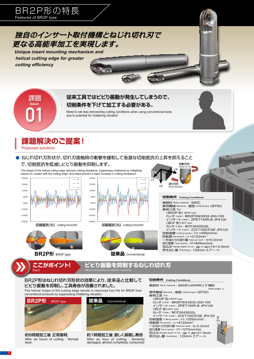
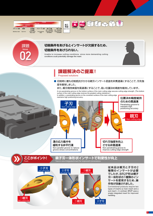
● 切削時に最も切削抵抗がかかる親刃インサート底面を非貫通溝にすることで、刃先強
課題解決のご提案! 度を確保しました。
Proposed solutions また、親刃側拘束面を貫通溝にすることで、高い位置決め精度を維持しています。
A non-penetrating groove on the bottom surface of the main cutting edge secures cutting edge strength. (The bottom
surface of the main cutting edge receives the greatest cutting resistance.)
● ねじれ切れ刃形状が、切れ刃接触時の衝撃を緩和して急激な切削抵抗の上昇を抑えること In addition, a penetrating groove on the constraint surface of the main cutting edge
maintains high positioning accuracy.
で、切削抵抗を低減しビビり振動を抑制します。 回転方向 位置決め精度維持
Hand of cut
The shape of the helical cutting edge reduces cutting resistance, suppresses chattering by mitigating +X のための貫通溝
impact on contact with the cutting edge, and helps prevent a rapid increase in cutting resistance. 子刃 Penetrating groove to
Sub cutting edge maintain high
X X +Y positioning accuracy
Y Y 送り方向
+Z
Z Z Feed direction
親刃
切削条件 Cutting Conditions Main cutting edge
被削材 Work material : S50C
使用機械 Machine : 縦型 Vertical type(BT50)
使用工具 Tool
(BR2P形) BR2P type
カッタ Cutter : BR2P3043S32-200-100
インサート Insert : ZPET150R-B JP4120
切削抵抗(N) cutting force N 切削抵抗(N) cutting force N (BCF形)
BCF type
( ) ( ) カッタ Cutter : BCF3043S32L
インサート Insert : ZCET150CE/SE JP4120
切削速度 Cutting speed:V c =200m/min
回転数 Revolution:n =2122min-1 溝の応力集中を 切れ刃強度を向上
一刃当たりの送り量 Feed per tooth : fz=0.2mm/t
送り速度 :V f =849mm/min 緩和する非平行溝 させる非貫通溝Feed speed
切込み Radial depth of cut : ap×ae=15×0.5mm Non-parallel groove to reduce Non-penetrating groove to
突き出し量 Overhang : 120mmエアー Air groove stress concentrations improve cutting edge strength
BR2P形 BR2P type 従来品 Conventional
ここがポイント! ビビり振動を抑制するねじれ切れ刃 ここがポイント! 親子刃一体形状インサートで利便性が向上Point Two-in-one integrated insert for improved convenience
Point Helical cutting edge to suppress chattering
BR2P形はねじれ切れ刃形状の効果により、従来品と比較して 切削条件 従来品は親刃と子刃のCutting Conditions ②子刃 2
Sub cutting edge
ビビり振動を抑制し、工具寿命が改善されました。 被削材 ②子刃 ①親刃Work material : SKD61(45HRC) 5°傾斜 種類のインサートが必要Sub cutting edge Main cutting edge
The helical shape of the cutting edge results in improved tool life for BR2P than
Slant angle: 5° でしたが、BR2P形は親子
Machine Vertical type
conventional products by suppressing chattering vibration.
使用機械 : 縦型 (BT50)
使用工具 Tool 刃一体形状の1種類のイン
BR2P形 (BR2P形)BR2P typeBR2P type 従来品 Conventional サートを使用するため、操カッタ Cutter : BR2P3043S32-200-100
インサート Insert : ZPET150R-B JP4120 作性が改善されました。
(BCF形)BCF type Conventional products require two
カッタ Cutter : BCF3043S32L types of inserts (a main insert and a
インサート Insert : ZCET150CE/SE JP4120 sub insert ). In contrast, BR2P uses a
切削速度 Cutting speed:V c =200m/min 5°
回転数
single integrated insert for improved
Revolution:n =2122min-1
一刃当たりの送り量 Feed per tooth : fz=0.3mm/t handling.
送り速度 Feed speed:V f =1273mm/min ①親刃
約6時間加工後 正常摩耗 約1時間加工後 激しく損傷し寿命 切込み
Radial depth of cut : ap×ae=3×3mm Main cutting edge
突き出し量 Overhang : 120mmエアー Air ①親刃 ②子刃
After six hours of cutting : Normal After an hour of cutting : Severely Main cutting edge Sub cutting edge
wear damaged; almost completely consumed
2
Page3
BR2P形の特長
Features of BR2P type
独自のインサート取付機構とねじれ切れ刃で TH308
JP4120
更なる高能率加工を実現します。 JS4030 加工 荒 中仕上JS4060 用途 Roughing Semi
ステンレス鋼 鋳鉄 炭素鋼 プリハードン鋼 焼入れ鋼 焼入れ鋼 Applications Finishing
Unique insert mounting mechanism and 合金鋼 45~55HRC 55~62HRCStainless steel Cast iron Carbon steel Pre-hardened Hardened steel Hardened steel
Alloy steel steel 45̃55HRC 55̃62HRC
helical cutting edge for greater
cutting efficiency
課題 切削条件をあげるとインサートが欠損するため、
Issue 切削条件をあげられない。
02 Unable to increase cutting conditions, since more demanding cutting conditions could potentially damage the insert.課題 従来工具ではビビり振動が発生してしまうので、
Issue 切削条件を下げて加工する必要がある。
01 Need to set less demanding cutting conditions when using conventional tools due to potential for chattering vibration 課題解決のご提案!
Proposed solutions
● 切削時に最も切削抵抗がかかる親刃インサート底面を非貫通溝にすることで、刃先強
課題解決のご提案! 度を確保しました。
Proposed solutions また、親刃側拘束面を貫通溝にすることで、高い位置決め精度を維持しています。
A non-penetrating groove on the bottom surface of the main cutting edge secures cutting edge strength. (The bottom
surface of the main cutting edge receives the greatest cutting resistance.)
● ねじれ切れ刃形状が、切れ刃接触時の衝撃を緩和して急激な切削抵抗の上昇を抑えること In addition, a penetrating groove on the constraint surface of the main cutting edge
maintains high positioning accuracy.
で、切削抵抗を低減しビビり振動を抑制します。 回転方向 位置決め精度維持
Hand of cut
The shape of the helical cutting edge reduces cutting resistance, suppresses chattering by mitigating +X のための貫通溝
impact on contact with the cutting edge, and helps prevent a rapid increase in cutting resistance. 子刃 Penetrating groove to
Sub cutting edge maintain high
X X +Y positioning accuracy
Y Y 送り方向
+Z
Z Z Feed direction
親刃
Main cutting edge
切削抵抗(N) cutting force(N) 切削抵抗(N) cutting force(N)
溝の応力集中を 切れ刃強度を向上
緩和する非平行溝 させる非貫通溝
Non-parallel groove to reduce Non-penetrating groove to
groove stress concentrations improve cutting edge strength
BR2P形 BR2P type 従来品 Conventional
ここがポイント! ビビり振動を抑制するねじれ切れ刃 ここがポイント! 親子刃一体形状インサートで利便性が向上Point Two-in-one integrated insert for improved convenience
Point Helical cutting edge to suppress chattering
BR2P形はねじれ切れ刃形状の効果により、従来品と比較して ②子刃 従来品は親刃と子刃の2
Sub cutting edge
ビビり振動を抑制し、工具寿命が改善されました。 ②子刃 ①親刃 種類のインサートが必要Sub cutting edge Main cutting edge
The helical shape of the cutting edge results in improved tool life for BR2P than でしたが、BR2P形は親子
conventional products by suppressing chattering vibration. 刃一体形状の1種類のイン
BR2P形 BR2P type 従来品 Conventional サートを使用するため、操
作性が改善されました。
Conventional products require two
types of inserts (a main insert and a
sub insert ). In contrast, BR2P uses a
single integrated insert for improved
handling.
①親刃
約6時間加工後 正常摩耗 約1時間加工後 激しく損傷し寿命
Main cutting edge ①親刃 ②子刃
After six hours of cutting : Normal After an hour of cutting : Severely Main cutting edge Sub cutting edge
wear damaged; almost completely consumed
3
Page4
BR2P形の特長
Features of BR2P type
課題 プレス金型の補修で用いられる肉盛溶接材の加工は、 課題 大物金型の大荒加工で安定して使用できる工具はないか?
Issue 工具寿命が短く、加工が難しい。何かいい工具はないか? Issue Is there a tool that can be used stably for the roughing cut of large-sized dies?
03 Tool life is reduced due to the difficulty in cutting the overlay welding material used for the press die repair. “Are there any suitable tools?” 04
課題解決のご提案! 課題解決のご提案!
Proposed solutions Proposed solutions
● 切込み量に変動のある肉盛溶接材の加工において、BR2P形はねじれ切れ刃の効果により、切込み量が増加 ● BR2P形はφ40、φ50の大型工具をラインナップしております。また、ボディやインサートの剛性を向上させた
しても切削抵抗の上昇を抑えることができるため、スムーズな加工を可能にします。 形状により、欠損を抑制します。
The BR2P enables smooth cutting of overlay welding materials with variable cutting depths because the helical cutting edge suppresses cutting resistance even as cutting depth Large φ40 and φ50 tools are available for the BR2P. In addition, improved body and insert rigidity helps suppress chipping.
increases.
厚 Thick 薄 Thin
切削条件 Cutting Conditions ボディ中心厚みを大きくすることで
被削材 Work material : ダクタイル鋳鉄 Nodular cast iron ボディ剛性を向上させています。
+TM-2000 *1
使用機械 Machine :縦型 Vertical type( BT50) 更に、インサート厚みを大きくするこ
使用工具 Tool
カッタ
とで高能率条件においても突発的な
Cutter : BR2P30S32-160-80
インサート Insert : ZPET150R-C JP4120 欠損を抑制します。
切削速度 Cutting speed : V c=100m/min
-1
Increasing the body center thickness improves the rigidity
回転数 Revolution : n=1070min of the body. Increasing the insert thickness enables to
一刃当たりの送り量 Feed per tooth : f z=0.17mm/t BR2P形 従来品 suppress sudden chipping under higher efficiency
送り速度 Feed speed : V f=370mm/min BR2P type Conventional machining.
切込み Radial depth of cut : ap×ae=3×1mm
突き出し量 Overhang : 80mm エアー Air
*1 TM-2000は東海溶業株式会社様の製品名です。
*1 TM-2000 is a product name of Tokai Yogyo Co., Ltd.
ここがポイント! 内部クーラントで切り屑排出性良好 ここがポイント! ニック付きインサートで切削抵抗を低減
Point Internal coolant improves chip evacuation Point Nicked inserts reduce cutting resistance
BR2P形はモジュラー、シャンクタイプのすべての径(MTシャンクを除く)にクーラント穴が付いていま
す。内部クーラントを使用すると切り屑排出性が向上するため、切り屑の噛み込みを低減します。
The BR2P has coolant holes for all diameters of the modular and shank types (except MT shank). The internal coolant improves the chip evacuation,
reducing chip biting.
内部クーラント穴付き
With internal coolant hole
BR2P形
BR2P type
4
厚 Thick
薄 Thin
Page5
BR2P形の特長
Features of BR2P type
課題 プレス金型の補修で用いられる肉盛溶接材の加工は、 課題 大物金型の大荒加工で安定して使用できる工具はないか?
Issue 工具寿命が短く、加工が難しい。何かいい工具はないか? Issue Is there a tool that can be used stably for the roughing cut of large-sized dies?
03 Tool life is reduced due to the difficulty in cutting the overlay welding material used for the press die repair. “Are there any suitable tools?” 04
課題解決のご提案! 課題解決のご提案!
Proposed solutions Proposed solutions
● 切込み量に変動のある肉盛溶接材の加工において、BR2P形はねじれ切れ刃の効果により、切込み量が増加 ● BR2P形はφ40、φ50の大型工具をラインナップしております。また、ボディやインサートの剛性を向上させた
しても切削抵抗の上昇を抑えることができるため、スムーズな加工を可能にします。 形状により、欠損を抑制します。
The BR2P enables smooth cutting of overlay welding materials with variable cutting depths because the helical cutting edge suppresses cutting resistance even as cutting depth Large φ40 and φ50 tools are available for the BR2P. In addition, improved body and insert rigidity helps suppress chipping.
increases.
厚 Thick 薄 Thin
ボディ中心厚みを大きくすることで
ボディ剛性を向上させています。
更に、インサート厚みを大きくするこ
とで高能率条件においても突発的な
欠損を抑制します。
Increasing the body center thickness improves the rigidity
of the body. Increasing the insert thickness enables to
BR2P形 従来品 suppress sudden chipping under higher efficiency
BR2P type Conventional machining.
切削条件 Cutting Conditions
被削材 Work material : S50C(220HB)
使用機械 Machine :縦型 Vertical type( BT50)
使用工具 Tool
カッタ Cutter : BR2P5063C508-200-120
インサート Insert : ZPET250R-N JP4120
切削速度 Cutting speed : V c=250m/min
回転数 Revolution : n=1592min-1
一刃当たりの送り量 Feed per tooth : f z=0.23mm/t
送り速度 Feed speed : V f=732mm/min
切込み Radial depth of cut : ap×ae=25×15mm
エアー Air
ここがポイント! 内部クーラントで切り屑排出性良好 ここがポイント! ニック付きインサートで切削抵抗を低減
Point Internal coolant improves chip evacuation Point Nicked inserts reduce cutting resistance
BR2P形はモジュラー、シャンクタイプのすべての径(MTシャンクを除く)にクーラント穴が付いていま ●φ50ニック付きインサートでの比較において、BR2P形は従来品と比較して切削抵抗を低減しています。
す。内部クーラントを使用すると切り屑排出性が向上するため、切り屑の噛み込みを低減します。 Using a φ50 nicked insert, the BR2P reduces cutting resistance compared to conventional products.
The BR2P has coolant holes for all diameters of the modular and shank types (except MT shank). The internal coolant improves the chip evacuation,
reducing chip biting. 切削条件 Cutting Conditions
BR2P形 3684 ■合力 被削材 Work material : S50C(220HB)
BR2P type Resultant force 使用機械 Machine :縦型 Vertical type( BT50)
使用工具 Tool
カッタ Cutter : BR2P5063C508-200-120
従来品A 4112 インサート Insert : ZPET250R-N JP4120
Conventional A 切削速度 Cutting speed : V c=141m/min
内部クーラント穴付き 回転数 Revolution : n=900min-1
With internal coolant hole 従来品B 4397 一刃当たりの送り量
Feed per tooth : f z=0.17mm/t
送り速度 Feed speed : V f=300mm/min
Conventional B 切込み Radial depth of cut : ap×ae=25×1mm
BR2P形 3000 3500 4000 4500 エアー Air
BR2P type
切削抵抗(N) Cutting force
5
厚 Thick
薄 Thin
Page6
R ap
L1 Rs
L
ラインナップ R ap L1 RsL
Line Up
シャンクタイプ Shank type
BR2P - - ap は数字、 は英文字が入ります。
Numeric figure in a circle and Alphabetical character comes in a square .
ap
R L1 Rs
L
R ap
L1 Rs R L1 Rs
L L
Fig.1( レギュラータイプ) Fig.2( ロング刃形)
Regular Type ap Long cutting edge
Fig.3
ap
(ロング刃形)
R L1 Rs Long cutting edge
L
寸 法 Size (mm) 適用インサーR ト Insert L1 Rs 希望小売
商品コード 在庫 ap R刃 R insert 外周刃 Peripheral in
Lsert 形状 価格(円)
Item Code Stock φDc R L φDs φD Suggested 2 ap L1 ℓs 商品コード 刃数 商品コード 刃数 Shape Retail Price
Item Code No.of Flutes Item Code
No.of
Flutes (¥)
R
BR2P16S16-130-50 ● 16 8 130 16 14.8 15 L1 50 80 Rs 31,540
L ZPET080R- ― ―
BR2P16S20-130-50 ● 16 8 130 20 14.8 15 50 80 32,160
BR2P20S20-130-50 ● 20 10 130 20 18.5 18 50 80 34,010
ZPET100R- ― ―
BR2P20S25-140-60 ● 20 10 140 25 18.5 18 60 80 35,930
BR2P25S25-140-60 ● 25 12.5 140 25 23.3 22 60 80 37,800
ZPET125R- 2 ― ― Fig.1
BR2P25S32-150-70 ● 25 12.5 150 32 23.3 2a2p 70 80 38,310
BR2P30S32-160-80 ● 30 15 160 32 28 27 80 80 ap MT5 41,810ZPET150R- ― ―
BR2P30S32-200-120 ● 30 15 200 32 28 27 120 80 47,320
BR2P32S32-160-80 ● 32 16 160 32 30 28 80 80 ZPET160R- ap ― ― 42,500
R MT5
BR2P40S42-200-120 ● 40 20 200 42 37.6 35 L1120 L80 ZP
REs T200R- ― ― 55,450
R M
ストレート BR2P2030S20-160-80 ● 20 10 160 20 18.5 30 80 80
a i 41,040
L1 Rs
シャンクタイプ BR2P2030S20-220-120 ● 20 10 220 20 18.5 30 120 100 L 50,960ZPET100R- CPMT070304
Straight BR2P2030S20-250-150 ● 20 10 250 20 18.5 30 150 100 R a i 56,7
M30
Shank Type BR2P2030S25-180-80 ● 20 10 180 25 18.5 30 80 100 L1 Rs 41,730
L
BR2P2535S25-160-80 ● 25 12.5 160 25 23.3 35 80 80 41,750
BR2P2535S25-200-100 ● 25 12.5 200 25 23.3 35 100 100 46,010
BR2P2535S25-250-150 ● 25 12.5 250 25 23.3 35 150 100 ZPET125R- CPMT070304 55,240
2 2 Fig.2
BR2P2535S32-200-100 ● 25 12.5 200 32 23.3 35 100 100 49,300
BR2P2535S32-250-150 ● 25 12.5 250 32 23.3 35 150 100 59,120
BR2P3043S32-200-100 ● 30 15 200 32 28 43 100 100 50,570
BR2P3043S32-250-150 ● 30 15 250 32 28 43 150 100 ZPET150R- CPMT090308 60,400
BR2P3043S32-260-180 ● 30 15 260 32 28ap 43 180 80 60,700
BR2P4050S42-200-100 ● 40 20 200 42 37.6 50 100 100 MT5 60,100
ZPET200R- CPMT090308
BR2P4050S42-250-150 ● 40 20 250 42 37.6 50 150 100 70,820
コンビネーションシャンクタイプ BR2P5063C508-200-120 ● 50 25 200 50.8 47.3 63 120 80 70,520ZPET250R- 2 CPMT120408 2 Fig.3
Combination Shank Type BR2P5063C508-250-170 ● 50 25 250 50R.8 47.3 63 a170 80 M 82,270i
L1 Rs
L
モジュラータイプ Modular type
BR2PM -M は数字、 は英文字が入ります。
Numeric figure in a circle and Alphabetical character comes in a square .
Lf E
M
R ap C
L1 Fig.4( モジュラータイプ)
L2 Modular type
寸 法 Size (mm) 適用インサート Insert
希望小売
商品コード 在庫 R刃 R insert 形状 価格(円)
Item Code Stock φDc R ap Lf φD2 M φDb L1 L2 C E 商品コード 刃数 Shape Suggested
Retail Price( ¥)
Item Code No.of Flutes
BR2PM16-M8 ● 16 8 15 32 8.5 M8 12.8 5.5 17 8 10 ZPET080R- 31,540
BR2PM20-M10 ● 20 10 18 38 10.5 M10 17.8 5.5 19 10 15 ZPET100R- 32,160
BR2PM25-M12 ● 25 12.5 22 38 12.5 M12 20.8 5.5 22 10 17 ZPET125R- 2 Fig.4 34,010
BR2PM30-M16 ● 30 15 27 43 17 M16 28.8 6 23 12 22 ZPET150R- 35,930
BR2PM32-M16 ● 32 16 28 43 17 M16 28.8 6 23 12 22 ZPET160R- 35,880
【注意】モジュラーミル専用シャンク/アーバとの接続端面部及びネジ部に潤滑剤は塗布しないでください。
【Note】Do not apply lubricants to the threaded section or end surface sections in contact with the dedicated shank/arbor for modular mills.
●印:標準在庫品です。●:Stocked items. 無印:受注生産品です。No mark:Manufactured upon request only.
6
φDc
φDs φDc φDc
φD3
φD2 φD2
φD
φD2
φDc φDc
φDs φDc φDc
φD3
φDs φDs
φDs φD2 φD2
φD
φD2
φD2
φDc
φDb
φDs φDc φDc
φD3 φDs φDs φDs
φD2 φD2
φD
φD2
φDs φDs
φDs
Page7
R ap
L1 Rs
L
ap
R
Lf Rs
L
ap
R L1 l f
L
MTシャンクタイプ MT Shank type
BR2P MT5- -M は数字、 は英文字が入ります。
Numeric figure in a circle and Alphabetical character comes in a square .
ap
MT5
Fig.5
(ロング刃形)
R Ma i Long cutting edge
L1 Rs
L
寸 法 Size (mm) 適用インサート Insert
希望小売
商品コード 在庫 R刃 R insert 外周刃 Peripheral insert 形状 価格(円)
Item Code Stockφ
Suggested
Dc R ap L L1 ℓs φD φD3 a i M Shape商品コード 刃数 商品コード 刃数 Retail Price
Item Code No.of No.of (¥)Flutes Item Code Flutes
BR2P4050MT5-90-M20 ● 40 20 50 219.5 90 37.6 50 M20 65,360
BR2P4050MT5-120-M16 40 20 50 249.5 120 37.6 40 M16 ―
BR2P4050MT5-120-M20 ● 40 20 50 249.5 120 37.6 50 M20 ZPET200R- 2 CPMT090308 2 69,740
BR2P4050MT5-170-M16 40 20 50 299.5 170 37.6 40 M16 ―
BR2P4050MT5-170-M20 ● 40 20 50 299.5 170 37.6 50 M20 73,220
BR2P5063MT5-100-M20 ● 50 25 63 229.5 100 47.3 50 M20 83,510
BR2P5063MT5-120-M16 50 25 63 249.5 120 129.5 44.399 47.3 6.5 40 M16 Fig.5 ―
BR2P5063MT5-120-M20 ● 50 25 63 249.5 120 47.3 50 M20 84,800
BR2P5063MT5-120-M24 50 25 63 249.5 120 47.3 50 M24
ZPET250R-
―
2 CPMT120408 2
BR2P5063MT5-150-M20 ● 50 25 63 279.5 150 47.3 50 M20 87,520
BR2P5063MT5-170-M16 50 25 63 299.5 170 47.3 40 M16 ―
BR2P5063MT5-170-M20 ● 50 25 63 299.5 170 47.3 50 M20 89,260
BR2P5063MT5-170-M24 50 25 63 299.5 170 47.3 50 M24 ―
部品番号 Parts
本体には付属しておりません(別売) Not included with product (sold separately)
部品名 クランプねじ ねじ焼き付き防止剤
Parts Clamp screw ドライバー /レンチ
Screw Driver/Wrench Screw anti-seizure agent
形状
Shape
A B
締付 希望小売 締付 希望小売 希望小売 希望小売 希望小売
R刃 トルク 価格(円) 外周刃 トルク 価格(円) R刃 形状 価格(円) 外周刃 形状 価格(円) 価格(円)
適用カッタ R insert Fastening Suggested Peripheral Fastening Suggested R insert Shape Suggested Peripheral Suggested Suggested torque Retail Price insert torque Retail Price Retail Price insert Shape Retail Price Retail Price
Cutter body (N・m) (¥) (N・m) (¥) (¥) (¥) (¥)
BR2P16S - -
P08-2507 1.1 920 ― ― ― 106-8IP A 2,080 ― ― ―
BR2PM16-M8
BR2P20S - -
― ― ― ― ― ―
BR2PM20-M10 P10-3008 2.0 940 106-10IP A 2,280
BR2P2030S - - P10-3007 2.0 1,000 106-10IP A 2,280
BR2P25S - -
― ― ― ― ― ―
BR2PM25-M12 P15-4011 2.9 1,060 106-15IP A 2,390
BR2P2535S - - P10-3007 2.0 1,000 106-10IP A 2,280
BR2P30S32- -
P-37 840
BR2PM30-M16
― ― ― ― ― ―
BR2P32S32- - P20-5013 4.9 1,060 105-20IP B 4,070
BR2PM32-M16
BR2P3043S32- - P15-4008 2.9 1,040 106-15IP A 2,390
BR2P40S42- - ― ― ― ― ― ―
BR2P4050S42- - P25-6016 8.0 1,380 105-25IP B 4,540
P15-4008 2.9 1,040 106-15IP A 2,390
BR2P4050MT5- -M
BR2P5063C508- -
P30-6019 9.8 1,780 P20-5011 4.9 980 105-30IP B 5,010 105-20IP B 4,070
BR2P5063MT5- -M
【注意】クランプねじは消耗品です。使用環境により交換寿命は変化しますので早めの交換をお願い致します。R刃用のクランプねじは予備が1本付属します。
【Note】The clamp screw is a consumable part. Since replacement life depends on the use environment, it is recommended that it be replaced at an early stage.
One spare clamp screw is provided for the R insert.
7
φDc
φDc φDc φDc
φD3
φD2 φD2
φD
φD2
φDs φDs
φDs
Page8
ラインナップ
Line Up
インサート Inserts
A T
T A T T
A A
R R R
rε
Fig-1 Fig-2 Fig-3 Fig-4
Bブレーカ Cブレーカ Nブレーカ(ニック付き) 外周刃
B breaker C breaker N breake(r With nick) Peripheral insert
P 鋼 Carbon Steel
K FC・FCD :一般切削・第一推奨
General cutting, First recommendation
M SUS 等 SUS, etc :一般切削・第二推奨
General cutting, Second recommendation
H 高硬度材 Hardened steels
TH3 寸 法 Size (mm)
コート
AJコート JSコート 希望小売
タイプ 商品コード 精度 AJ coated JS coated 形状 価格(円)
Type Tolerance
TH3 coated
Item code
Class R rε A B T Shape Suggested
Retail Price(¥)
TH308 JP4120 JS4030 JS4060
ZPET080R-B ● ● ● 8 ― 16.9 ― 3.6 3,680
ZPET100R-B ● ● ● 10 ― 20.3 ― 4.7 4,080
ZPET125R-B ● ● ● 12.5 ― 25.4 ― 6 4,660
R刃 ZPET150R-B E級
E
● ● ● 15 ― 30.5 ― 7.5 Fig-1 5,630
R insert
ZPET160R-B ● ● ● 16 ― 32.5 ― 7.5 6,070
ZPET200R-B ● ● ● 20 ― 40.4 ― 8.8 6,220
ZPET250R-B ● ● ● 25 ― 46.0 ― 10.8 7,500
ZPET080R-C ● ● 8 ― 16.9 ― 3.6 3,680
ZPET100R-C ● ● 10 ― 20.3 ― 4.7 4,080
ZPET125R-C ● ● 12.5 ― 25.4 ― 6 4,660
R刃 ZPET150R-C E級
E
● ● 15 ― 30.5 ― 7.5 Fig- 2 5,630
R insert
ZPET160R-C ● ● 16 ― 32.5 ― 7.5 6,070
ZPET200R-C ● ● 20 ― 40.4 ― 8.8 6,220
ZPET250R-C ● ● 25 ― 46.0 ― 10.8 7,500
R刃 ZPET200R-N E級 ― ● ● ● 20 ― 40.4 ― 8.8 6,220Fig- 3
R insert ZPET250R-N E ― ● ● ● 25 ― 46.0 ― 10.8 7,500
CPMT070304 ― ● ― 0.4 7.14 7.14 3.18 780
外周刃
Peripheral CPMT090308
M級
M
― ● ― 0.8 9.525 9.525 3.18 Fig- 4 910
insert
CPMT120408 ― ● ― 0.8 12.7 12.7 4.76 1,680
【注意】JSコートは通電式タッチセンサーに反応しませんのでご注意ください。
【Note】Please note that the JS coating does not cause a reaction in conductive touch sensors.
コーティング材種使い分け Insert grade selection
材種名 用途 特長
Grade Application Features
TH308 高硬度鋼 超微粒超硬合金とTH3コーテイングを採用。
Features micro grain substrate and TH3 coating.
High-hardened steel 高硬度材加工の汎用性に優れる。Offers excellent versatility for cutting high hard materials.
30~50HRCの合金鋼・
焼入れ鋼・肉盛溶接材 微粒超硬合金と AJコーテイングを採用。Features fine grain substrate and AJ coating.JP4120 Alloy steel, hardened steel, and overlay 鋼一般から焼入れ鋼の加工に優れる。Suitable for cutting materials ranging from general steel to hardened steel.
welding materials with hardness ranging from
30 to 50 HRC
鋼一般 粗粒超硬合金と JSコーテイングを採用。Features rough grain substrate and JS coating.JS4030
General steel 鋼一般の切削に優れる。Suitable for cutting general steel.
JS4060 不安定切削・湿式切削 粗粒超硬合金と JSコーテイングを採用。
Features rough grain substrate and JS coating.
Unstable cutting/wet cutting 軟鋼の不安定切削や湿式切削に優れる。Suitable for unstable mild steel cutting and wet cutting.
●印:標準在庫品です。●:Stocked items. 無印:受注生産品です。No mark:Manufactured upon request only. ー印:製作いたしません。ー:No Manufactured.
8
B
11°
80°
Page9
B、C、Nブレーカの使い分け Suitable uses for B, C, and N chipbreakers
被削材硬度 Hardness of work material
20 30 40 50 60
刃先強度
(高)
Cutting force
High
Cブレーカ
C breaker
JP4120 TH308
Bブレーカ
B breaker
JS4060 JS4030 JP4120
Nブレーカ(ニック付き)
切れ味 N breake(r With nick)
(良) JS4060 JS4030 JP4120
Cutting force
Low
被削材 FC/FCD S50C〜 P20、プリハードン鋼
Work material Pre-hardened steels
SKD61 SKD11
ステンレス鋼 肉盛溶接材 /フレームハード材
Stainless steel Welding material / Flame hardening steel
インサート取付け手順 Insert setup procedures
インサート座面の清掃
Clean the insert seat:
1 エアーブローなどで、インサート座面を清掃ください。
Clean the insert seat surface, such as by using an air blower.
親刃側
▼ On the main cutting edge side
インサートは、親刃と子刃が一体の形状です。
The insert is formed by integrating a main cutting edge and a sub cutting edge. 親刃マーク
2 ボディ親刃側の座へは親刃マークを先端方向へ向けてインサートを着座させてください。 Main cutting edge mark
ボディ子刃側の座へは親刃マークをシャンク方向へ向けてインサートを着座させてください。
On the main cutting edge side, position the insert on the body seat with the main cutting edge mark facing toward the tip.
On the sub cutting edge side, position the insert on the body seat with the main cutting edge mark facing toward the shank.
▼
クランプねじを締め付けてインサートを固定する。
Tighten the clamp screw to fix the insert.
3 クランプねじのドライブサイズは、トルクス プラス®です。
トルクス プラス®に対応したレンチをご使用ください。 子刃側On the sub
The drive type of the clamp screw is Torx Plus® cutting edge side
Use a Torx Plus® wrench.
▼
4 締付け完了。This concludes the insert setup. クランプねじ ドライバー レンチ
Clamp Screw Screw Driver Wrench
トルクス プラス®
Torx Plus®
トルクス プラスⓇ、Torx PlusⓇは、米国アキュメント インテクチュアル プロパティーズ エルエルシー社の登録商標です。
Torx Plus® is a trademark of Acument Intellectual Properties LLC in the United States.
9
Page10
ラインナップ
Line Up
モジュラーミル専用シャンク The Shanks for Modular Mill モジュラーミル用アーバ Modular Mill Arbor
超硬 商品コード
寸 法 Size (mm) 適用 希望小売価格(円)
シャンク 寸 法 Size (mm) Carbide Shank カッタ 商品コード 適用カッタ(θκ)Item code φD2 M L3 L Lf L2 L1 Rs φD3 φDs φD4 Cutter Suggested BT30body Retail Pric(e ¥) Item code φD2 M φD3φDs L3 L Lf L4 L1 θn Cutter body
ASC16-8.5-95-30Z ● 127 95 30 62 65 41,820
56 30 26 5 31 17° φ10(18.8°)φ 12(17.8°)
ASC16-8.5-120-55Z ● 152 120 55 87 65
BT30-6.5-30-9.7
45,700
ASC16-8.5-140-75Z ● 8.5 M8 172 140 32 75 107 65 14.5 16 15.5 A φ16 48,660 BT30-6.5-55-9.7 6.5 M6 9.7 25 81 55 26 10 36 9.6°φ10(13°) φ12(12.3°)
ASC16-8.5-160-95Z ● 192 160 95 127 65 51,210 BT30-6.5-80-9.7 106 80 26 10 36 6.2°φ10(9.9°) φ12(9.4°)
L3 ASC16-8.5-160-30Z ● 192 160 30 62 130 51,210 L3 22 48.4 BT30-8.5-25-15 57 25 32 5 37 20.6°φ16(15.5°)
L
L1 ASC20-10.5-120-50Z ● 158 120 50 88 70 49,370
L f L
L1 θκ BT30-8.5-50-15L f s 8.5 M8 15 30
82 50 32 10 42 10.6°φ16(10.8°)
L2 R ASC20-10.5-170-90Z ● 170 90 128 80
10.5
208
M10 38 18.5 20 19.5 A φ20
55,290 L4 M
ASC20-10.5-220-120Z ● 258 220 120 158 100
BT30-8.5-75-15 107 75 32 10 42 6.6°φ16(8.2°)
60,800
ASC20-10.5-270-150Z ● 308 270 150 188 120 77,120 BT30-10.5-20-18 58 20 38 5 43 29.5°φ20(13.3°)
M
ASC20-10.5-220-50Z ● 258 220 170 BT30-10.5-45-18 10.5 M10 18 35 83 45 38 10 48 13.7°φ20(9.2°)
10.5 M10 38 50 88
●
18.5 φ20
60,800
Aタイプ A type ASC20-10.5-270-50Z 308 270 220
20 19.5 A BT30
77,120
θn
BT30-10.5-70-18 108 70 38 10 48 8.1°φ20(7.1°)
ASC25-12.5-145-65 ● 183 145 65 103 80 56,510 BT30-12.5-15-21 53 15 38 5 43 32.3°φ25(11.9°)
ASC25-12.5-215-115 ● 253 215 115 153 100
12.5 M12 38 23 25 - B
66,200
L3 ASC25-12.5-265-145 ● 303 265 145 183 120
φ25 BT30-12.5-40-21 78 40 38 10 48 17.6°φ25(8°)
L 77,120 12.5 M12 21 40
L1 ASC25-12.5-315-195 ● 353 315 195 233 120 99,450 BT30-12.5-65-21 103 65 38 10 48 9.8°φ25(6°)
L f L2 Rs ASC25-12.5-265-65 ● 303 265 200 77,120 BT30-12.5-85-21 123 85 38 10 48 7.2°φ25(5°)
●
12.5 M12 38 65 103
353 315 250
23 25 - B φ25
ASC25-12.5-315-65 99,450 BT30-17-10-28 53 10 43 5 48 31° φ30(9.1°) φ32(8°)
ASC32-17-160-80 ● 203 160 80 123 80
※首部は、ユーザ様にて追加工可能です。
85,680
M ※For neck section, additional machining to user BT30-17-35-28 17 M16 28 40 78 35 43 10 53 13.5°φ30(6.1°) φ32(5.3°)
ASC32-17-210-110 ● 253 210 110 153 100
φ30
86,700 specifications is possible.
120 BT30-17-60-28
103 60 43 10 53 6.8°φ30(4.6°) φ32(4°)
Bタイプ B type ASC32-17-260-140 ● 17 M16 303 260 43 140 183 28 32 - B φ32 103,020
ASC32-17-310-190 ● 353 310 190 233 120 139,740 【注意】加工状況により振動が懸念される場合は、1.切り込み深さ(ap)を低減する 2.一刃当りの送り(fz)を低減する方法で調整ください。
ASC32-17-360-240 ● 403 360 240 283 120 176,460 【 Note】 If vibrations are a concern due to the processing conditions, adjust conditions by 1.reducing cutting depth (ap) or 2.reducing per-flute feed rate (fz).
ASC32-17-260-80 ● 303 260 180 103,020
ASC32-17-310-80 ● 17 M16 353 310 43 80 123 230 28 32 - B
φ30
139,740 商品コード 寸 法 Size (mm) 適用カッタ(θκ)
ASC32-17-360-80 ● 403 360 280
φ32
176,460 BT40 Item code φD2 M φD3φDs L3 L Lf L4 L1 θn Cutter body
【注意】市販のミ-リングチャック、焼ばめホルダーにて使用できます。 【 Note】 Commercial milling chucks or shrink-fit holders can be used. BT40-6.5-30-9.7 56 30 26 5 31 17° φ10(26.6°) φ12(25.7°)
BT40-6.5-55-9.7 81 φ10(18.8°) φ12(18.1°)
6.5 M6 9.7 25
55 26 10 36 9.6°
BT40-6.5-80-9.7 106 80 26 10 36 6.2°φ10(14.4°) φ12(13.9°)
BT40-6.5-130-9.7 156 130 26 10 36 3.6°φ10(9.8°) φ12(9.5°)
L3 27 65.4 BT40-8.5-25-15 57 25 32 5 37 20.6°φ16(23.5°)
モジュラーミル専用シャンク Lf LThe Shanks for Modular Mill BT40-8.5-50-15 82 50 32 10 42 10.6°φ16(16.6°)L θκ1 8.5 M8 15 30
M BT40-8.5-75-15 107 75 32 10 42 6.6°φ16(12.7°)
鋼
L4
シャンク Steel Shank 寸 法 希望小売 BT40-8.5-125-15 157 125 32 10 42 3.7°φ16(8.7°)Size (mm)
商品コード 価格(円) BT40-10.5-20-18 58 20 38 5 43 29.5°φ20(21.4°)
BT40-10.5-45-18 18 35
83 45 38 10 48 13.7°φ20(15°)
L3 Item code Suggested 10.5 M10
L φD2 M L3 L Lf L2 L1 Rs φD3 φDs φD4 Retail Pric(e ¥) BT40-10.5-70-18 108 70 38 10 48 8.1°φ20(11.6°)
L1
L f L2 Rs θn BT40 BT40-10.5-120-18 158 120 38 10 48 4.4°φ20(7.9°)
BT40-12.5-15-21 53 15 38 5 43 32.3°φ25(20.8°)
BT40-12.5-40-21 78
12.5 M12 21 40
40 38 10 48 17.6°φ25(14.2°)
M
AS16-8.5-95-15 ● 8.5 M8 127 95 32 15 47 8 0 14.5 16 15.5 A φ16 24,480 BT40-12.5-65-21 103 65 38 10 48 9.8°φ25(10.8°)
BT40-12.5-115-21 153 115 38 10 48 5.2°φ25(7.2°)
Aタイプ (首テ-パ) A type (Tapered neck) BT40-17-10-28 53 10 43 5 48 45° φ30(18.3°) φ32(17.2°)
※首部は、ユーザ様にて追加工可能です。 BT40-17-35-28 28 48
78 35
17 M16
43 10 53 21.8°φ30(12.4°) φ32(11.7°)
※For neck section, additional machining to user
specifications is possible. BT40-17-60-28 103 60 43 10 53 11.3°φ30(9.4°) φ32(8.8°)L3
L
AS20-10.5-100-20 ● 10.5 M10 138 100 38 20 58 80 18 20 ̶ B φ20 27,540 BT40-17-110-28 153
110 43 10 53 5.7°φ30(6.3°) φ32(5.9°)
L1 L2 Rs
L f 【注意】加工状況により振動が懸念される場合は、1.切り込み深さ(ap)を低減する 2.一刃当りの送り(fz)を低減する方法で調整ください。
【 Note】 If vibrations are a concern due to the processing conditions, adjust conditions by 1.reducing cutting depth (ap) or 2.reducing per-flute feed rate (fz).
M AS25-12.5-115-35 ● 12.5 M12 153 115 38 35 73 80 23 25 ̶ B φ25 30,810 商品コード 寸 法 Size (mm)HSK 適用カッタ(θκ)
希望小売価格(円)
Suggested
Item code Cutter body
Bタイプ φD2 M φD3φDs L3 L Lf L4 L1 θn Retail Pric(e ¥)B type (モジュラーミルタイプ)
HSK Arbor HSK-A63-10.5-30-18
● 20.8 68 30 38 ̶ 38 3° φ20(18.3°) 82,220
L Modular Mill Type HSK-A63-10.5-70-18 ● 25 108 70 38 10 48 3° φ20(11.6°) 84,460 3 φ30
L
10.5 M10 18
AS32-17-110-30 ● 17 M16 153 110 43 30 73 80 28 32 ̶ B 36,930
φ32
HSK-A63-10.5-70-18S 48 108 70 38 10 48 12° φ20(11.6°) -
L1 L2 Rs L3 26 32
L f HSK-A63-10.5-120-18 ● 30.2 158 120 38 10 48 3° φ20(7.9°) 88,130 L θκ
L1 HSK-A63-12.5-35-21 ● 24.3 73 35 38 ̶ 38 3° φ25(15.2°) 83,030
Lf L4 M HSK-A63-12.5-65-21 ● 27.5 103 65 38 10 48 3° φ25(10.8°) 84,050
M φ30 12.5 M12 21
AS42-17-360-90 ● 17 M16 403 360 43 90 70 270 28 42 ̶ C 70,380 HSK-A63-12.5-65-21S 48 103 65 38 10 48 12° φ25(10.8°) -
Cタイプ C type φ32 HSK-A63-12.5-115-21 ● 32.7 153 115 38 10 48 3° φ25(7.2°) 88,440
HSK-A63-17-40-28 ● 31.8 83 40 43 ̶ 43 3° φ30(11.7°) φ32(11°) 83,030
【注意】市販のミ-リングチャックにて使用できます。 【 Note】 Commercial milling chucks can be used. θn HSK‐A63 HSK-A63-17-60-28 ● 33.9 103 60 43 10 53 3° φ30(9.4°) φ32(8.8°) 84,050
17 M16 28
HSK-A63-17-60-28S 48 103 60 43 10 53 9.5°φ30(9.4°) φ32(8.8°) -
HSK-A63-17-110-28 ● 39.2 153 110 43 10 53 3° φ30(6.3°) φ32(5.9°) 87,930
10
φD2
φD2 φD
φD2
2
φD2 φD3
φD3
φD3
φD4
φD4
φD3
φD3
φDs φDs
φDs φDs φDs
在庫 Stock
在庫 Stock
形状 Shape 形状
Shape
適用カッタ
Cutter body
φD2 φD2
φD 2
φD3
φ
φD 3
D3
φDs φD s
φDs
φ46
φ63
φ63
在庫 Stock
在庫 Stock 在庫 Stock
Page11
モジュラーミル専用シャンク The Shanks for Modular Mill モジュラーミル用アーバ Modular Mill Arbor
寸 法 Size (mm) 適用
超硬 商品コード カッタ 希望小売価格(円)シャンク Carbide Shank Suggested 商品コード 寸 法 Size (mm) 適用カッタ(θκ)Item code φD2 M L3 L Lf L2 L1 Rs φD3 φDs φD4 Cutter BT30body Retail Pric(e ¥) Item code φD2 M φD3φDs L3 L Lf L4 L1 θn Cutter body
ASC16-8.5-95-30Z ● 127 95 30 62 65 41,820
ASC16-8.5-120-55Z ● 152 120 55 87 65
BT30-6.5-30-9.7 56 30 26 5 31 17° φ10(18.8°)φ 12(17.8°)
45,700
ASC16-8.5-140-75Z ● 8.5 M8 172 140 32 75 107 65 14.5 16 15.5 A φ16 48,660 BT30-6.5-55-9.7 6.5 M6 9.7 25 81 55 26 10 36 9.6°φ10(13°) φ12(12.3°)
ASC16-8.5-160-95Z ● 192 160 95 127 65 51,210 BT30-6.5-80-9.7 106 80 26 10 36 6.2°φ10(9.9°) φ12(9.4°)
L3 ASC16-8.5-160-30Z ● 192 160 30 62 130 51,210 L3 22 48.4 BT30-8.5-25-15 57 25 32 5 37 20.6°φ16(15.5°)
L
L1 ASC20-10.5-120-50Z ● 158 120 50 88 70 49,370
L f L
L1 θκ BT30-8.5-50-15 8.5 M8 15 30 82 50 32 10 42 10.6°φ16(10.8°)L f L2 Rs ASC20-10.5-170-90Z ● 208 170 90 128 80 M
10.5 M10 38 18.5 20 19.5 A φ20
55,290 L4
107 75 32 10 42 6.6°φ16(8.2°)
ASC20-10.5-220-120Z ● 258 220 120 158 100
BT30-8.5-75-15
60,800
ASC20-10.5-270-150Z ● 308 270 150 188 120 77,120 BT30-10.5-20-18 58 20 38 5 43 29.5°φ20(13.3°)
M
ASC20-10.5-220-50Z ● 220 170 BT30-10.5-45-18 10.5 M10 18 35 83 45 38 10 48 13.7°φ20(9.2°)
●
10.5
258
M10 38 50 88 18.5
308 270 220
20 19.5 A φ20
60,800
θn BT30
Aタイプ A type ASC20-10.5-270-50Z 77,120 BT30-10.5-70-18 108 70 38 10 48 8.1°φ20(7.1°)
ASC25-12.5-145-65 ● 183 145 65 103 80 56,510 BT30-12.5-15-21 53 15 38 5 43 32.3°φ25(11.9°)
ASC25-12.5-215-115 ● 253 215 115 153 100
L3 ●
12.5 M12 38 23 25 - B
66,200
ASC25-12.5-265-145 303 265 145 183 120
φ25 BT30-12.5-40-21 78 40 38 10 48 17.6°φ25(8°)
L 77,120 12.5 M12 21 40
L ASC25-12.5-315-195 ● 353 315 195 233 120 99,450 BT30-12.5-65-21 103 65 38 10 48 9.8°φ25(6°)1
L f L2 Rs ASC25-12.5-265-65 ● 303 265 200 77,120 BT30-12.5-85-21 123 85 38 10 48 7.2°φ25(5°)
12.5 M12 38 65 103 23 25 - B φ25
ASC25-12.5-315-65 ● 353 315 250 99,450
※首部は、ユーザ様にて追加工可能です。
BT30-17-10-28 53 10 43 5 48 31° φ30(9.1°) φ32(8°)
ASC32-17-160-80 ● 203 160 80 123 80 85,680
M ※For neck section, additional machining to user BT30-17-35-28 17 M16 28 40 78 35 43 10 53 13.5°φ30(6.1°) φ32(5.3°)
ASC32-17-210-110 ● 253 210 110 153 100 86,700 specifications is possible.
103 60 43 10 53 6.8°φ30(4.6°) φ32(4°)
Bタイプ B type ASC32-17-260-140 ● 17 M16 303 260 43 140 183 120 28
φ30 BT30-17-60-28
32 - B φ32 103,020
ASC32-17-310-190 ● 353 310 190 233 120 139,740 【注意】加工状況により振動が懸念される場合は、1.切り込み深さ(ap)を低減する 2.一刃当りの送り(fz)を低減する方法で調整ください。
ASC32-17-360-240 ● 403 360 240 283 120 176,460 【 Note】 If vibrations are a concern due to the processing conditions, adjust conditions by 1.reducing cutting depth (ap) or 2.reducing per-flute feed rate (fz).
ASC32-17-260-80 ● 303 260 180 103,020
ASC32-17-310-80 ● 17 M16 353 310 43 80 123 230 28 32 - B
φ30
139,740 寸 法 Size (mm)
ASC32-17-360-80 ● 403 360 280
φ32
176,460 BT40 商品コード 適用カッタ(θκ)Item code φD2 M φD3φDs L3 L Lf L4 L1 θn Cutter body
【注意】市販のミ-リングチャック、焼ばめホルダーにて使用できます。 【 Note】 Commercial milling chucks or shrink-fit holders can be used. BT40-6.5-30-9.7 56 30 26 5 31 17° φ10(26.6°) φ12(25.7°)
BT40-6.5-55-9.7 9.7 25
81 55 26 10 36 9.6°φ10(18.8°) φ12(18.1°)
6.5 M6
BT40-6.5-80-9.7 106 80 26 10 36 6.2°φ10(14.4°) φ12(13.9°)
BT40-6.5-130-9.7 156 130 26 10 36 3.6°φ10(9.8°) φ12(9.5°)
L3 27 65.4 BT40-8.5-25-15 57 25 32 5 37 20.6°φ16(23.5°)
モジュラーミル専用シャンク Lf LThe Shanks for Modular Mill L θκ BT40-8.5-50-151 8.5 M8 15 30 82 50 32 10 42 10.6°φ16(16.6°)
L M
BT40-8.5-75-15 107 75 32 10 42 6.6°φ16(12.7°)
鋼
4
シャンク Steel Shank 寸 法 希望小売 BT40-8.5-125-15 157 125 32 10 42 3.7°φ16(8.7°)Size (mm)
商品コード 価格(円) BT40-10.5-20-18 58 20 38 5 43 29.5°φ20(21.4°)
BT40-10.5-45-18 18 35
83
10.5 M10
45 38 10 48 13.7°φ20(15°)
L3 Item code Suggested
L φD2 M L3 L Lf L2 L1 Rs φD3 φDs φD4 Retail Pric(e ¥) BT40-10.5-70-18 108 70 38 10 48 8.1°φ20(11.6°)
L1
L f L2 Rs θn BT40 BT40-10.5-120-18 158 120 38 10 48 4.4°φ20(7.9°)
BT40-12.5-15-21 53 15 38 5 43 32.3°φ25(20.8°)
BT40-12.5-40-21 78 40 38 10 48 17.6°φ25(14.2°)
M
AS16-8.5-95-15 ● 8.5 M8 127 95 32 15 47 8 0 14.5 16 15.5 A φ16 24,480 12.5 M12 21 40BT40-12.5-65-21 103 65 38 10 48 9.8°φ25(10.8°)
BT40-12.5-115-21 153 115 38 10 48 5.2°φ25(7.2°)
Aタイプ (首テ-パ) A type (Tapered neck) BT40-17-10-28 53 10 43 5 48 45° φ30(18.3°) φ32(17.2°)
※首部は、ユーザ様にて追加工可能です。 BT40-17-35-28 28 48
78 35 43 10 53 21.8°φ30(12.4°) φ32(11.7°)
※For neck section, additional machining to user 17 M16
specifications is possible. BT40-17-60-28 103 60 43 10 53 11.3°φ30(9.4°) φ32(8.8°)L3 AS20-10.5-100-20 ● 10.5 M10 138 100 38 20 58 80 18 20 ̶ B φ20 27,540
L BT40-17-110-28 153 110 43 10 53 5.7°φ30(6.3°) φ32(5.9°)
L1 L2 Rs
L f 【注意】加工状況により振動が懸念される場合は、1.切り込み深さ(ap)を低減する 2.一刃当りの送り(fz)を低減する方法で調整ください。
【 Note】 If vibrations are a concern due to the processing conditions, adjust conditions by 1.reducing cutting depth (ap) or 2.reducing per-flute feed rate (fz).
M AS25-12.5-115-35 ● 12.5 M12 153 115 38 35 73 80 23 25 ̶ B φ25 30,810
HSK 商品コード
寸 法 Size (mm) 適用カッタ(θκ) 希望小売価格(円)
Suggested
Item code φD2 M φD3φDs L3 L Lf L4 L1 θn Cutter bodyBタイプ Retail Pric(e ¥)B type (モジュラーミルタイプ)
HSK Arbor HSK-A63-10.5-30-18
● 20.8 68 30 38 ̶ 38 3° φ20(18.3°) 82,220
L Modular Mill Type HSK-A63-10.5-70-18 ● 25 108 70 38 10 48 3° φ20(11.6°) 84,460 3 φ30
L
10.5 M10 18
AS32-17-110-30 ● 17 M16 153 110 43 30 73 80 28 32 ̶ B 36,930
φ32
HSK-A63-10.5-70-18S 48 108 70 38 10 48 12° φ20(11.6°) -
L1 L2 Rs L3 26 32
L f HSK-A63-10.5-120-18 ● 30.2 158 120 38 10 48 3° φ20(7.9°) 88,130 L θκ
L1 HSK-A63-12.5-35-21 ● 24.3 73 35 38 ̶ 38 3° φ25(15.2°) 83,030
Lf L4 M HSK-A63-12.5-65-21 ● 27.5 103 65 38 10 48 3° φ25(10.8°) 84,050
M φ30 12.5 M12 21
AS42-17-360-90 ● 17 M16 403 360 43 90 70 270 28 42 ̶ C 70,380 HSK-A63-12.5-65-21S 48 103 65 38 10 48 12° φ25(10.8°) -
Cタイプ C type φ32 HSK-A63-12.5-115-21 ● 32.7 153 115 38 10 48 3° φ25(7.2°) 88,440
HSK-A63-17-40-28 ● 31.8 83 40 43 ̶ 43 3° φ30(11.7°) φ32(11°) 83,030
【注意】市販のミ-リングチャックにて使用できます。 【 Note】 Commercial milling chucks can be used. θn HSK‐A63 HSK-A63-17-60-28 ● 33.9 103 60 43 10 53 3° φ30(9.4°) φ32(8.8°) 84,050
17 M16 28
HSK-A63-17-60-28S 48 103 60 43 10 53 9.5°φ30(9.4°) φ32(8.8°) -
HSK-A63-17-110-28 ● 39.2 153 110 43 10 53 3° φ30(6.3°) φ32(5.9°) 87,930
●印:標準在庫品です。●:Stocked items. 無印:受注生産品です。No mark:Manufactured upon request only.
11
φD
φD2 φD2
φD2 2
φD2 φD3
φD3
φD3
φD4
φD4
φD3
φD3
φDs φDs
φDs φDs φDs
在庫 Stock
在庫 Stock
形状 Shape 形状
Shape
適用カッタ
Cutter body
φD2 φD2
φD 2
φD3
φ
φD 3
D3
φDs φD s
φDs
φ46
φ63
φ63
在庫 Stock
在庫 Stock 在庫 Stock
Page12
標準切削条件表
Recommended cutt ing condi t ions
■ スチールシャンク Steel Shank ※赤字は第 1推奨材種です。Red indicates primary recommended insert grades.
φ16 φ20 φ25
>3Dc >3Dc >3Dc
被削材 推奨材種 切削条件 Recommended Cutting フル R 加工 中仕上げ フル R 加工 中仕上げ フル R 加工 中仕上げWork material inserts grade conditions 汎用 高能率条件 汎用条件 汎用 高能率条件 汎用条件 3Dc~5Dc 5Dc~ 汎用 高能率条件 汎用条件 3Dc~5Dc 5Dc~
General Full R cutting in Semi-finishing General Full R cutting in Semi-finishing General Full R cutting in Semi-finishing
purpose high efficiency in general purpose high efficiency in general purpose high efficiency in general
machining machining machining machining machining machining
n (min-1) 3,190 4,380 4,980 2,550 3,510 3,980 1,760 1,520 2,040 2,810 3,190 1,410 1,210
炭素鋼 vc (m/min) 160 220 250 160 220 250 110 95 160 220 250 110 95
合金鋼 JS4030
Carbon Steels
vf (mm/min) 1,280 880 2,990 1,020 710 2,390 530 370 820 850 1,920 430 300
JP4120
Alloy Steels fz (mm/t) 0.2 0.1 0.3 0.2 0.1 0.3 0.15 0.12 0.2 0.15 0.3 0.15 0.12
(30HRC 以下) JS4060
(30HRC or less) ap (mm) 3 8 0.5 4 10 0.7 2 1 5 12.5 1 2.5 1.5
ae (mm) 3 1 1 4 2 1.2 2 1 5 3 2 2.5 1.5
n (min-1) 2,390 2,590 3,590 1,910 2,070 2,870 1,360 1,120 1,530 1,660 2,300 1,090 900
炭素鋼 JP4120 vc (m/min) 120 130 180 120 130 180 85 70 120 130 180 85 70
合金鋼 JS4030 vf (mm/min) 720 520 1,440 580 420 1,150 330 230 460 500 920 270 180
Carbon Steels
Alloy Steels JS4060 fz (mm/t) 0.15 0.1 0.3 0.15 0.1 0.3 0.12 0.1 0.15 0.15 0.3 0.12 0.1
(30 ~ 45HRC) TH308 ap (mm) 3 8 0.5 4 10 0.7 2 1 5 12.5 1 2.5 1.5
ae (mm) 3 1 1 4 2 1.2 2 1 5 3 2 2.5 1.5
n (min-1) 3,190 4,380 4,980 2,550 3,510 3,980 1,760 1,520 2,040 2,810 3,190 1,410 1,210
JP4120 vc (m/min) 160 220 250 160 220 250 110 95 160 220 250 110 95鋳鉄
Cast Iron JS4060 vf (mm/min) 1,280 880 2,990 1,020 710 2,390 530 370 820 850 1,920 430 300
FC JS4030 fz (mm/t) 0.2 0.1 0.3 0.2 0.1 0.3 0.15 0.12 0.2 0.15 0.3 0.15 0.12
FCD TH308 ap (mm) 3 8 0.5 4 10 0.7 2 1 5 12.5 1 2.5 1.5
ae (mm) 3 1 1 4 2 1.2 2 1 5 3 2 2.5 1.5
n (min-1) 1,990 ― 2,990 1,600 ― 2,390 1,120 960 1,280 ― 1,910 900 770
vc (m/min) 100 ― 150 100 ― 150 70 60 100 ― 150 70 60
ステンレス鋼 JS4060 vf (mm/min) 600 ― 1,200 480 ― 960 270 200 390 ― 770 220 160
Stainless Steels
SUS JP4120 fz (mm/t) 0.15 ― 0.3 0.15 ― 0.3 0.12 0.1 0.15 ― 0.3 0.12 0.1
ap (mm) 3 ― 0.5 4 ― 0.7 2 1 5 ― 1 2.5 1.5
ae (mm) 3 ― 1 4 ― 1.2 2 1 5 ― 2 2.5 1.5
n (min-1) 1,990 ― 2,990 1,600 ― 2,390 1,120 960 1,280 ― 1,910 900 770
vc (m/min) 100 ― 150 100 ― 150 70 60 100 ― 150 70 60
焼入れ鋼 JP4120 vf (mm/min) 480 ― 1,800 390 ― 1,440 180 140 310 ― 1,150 150 110
Hardened Steels
(45 ~ 55HRC) TH308 fz (mm/t) 0.12 ― 0.3 0.12 ― 0.3 0.08 0.07 0.12 ― 0.3 0.08 0.07
ap (mm) 1.5 ― 0.5 2 ― 0.7 1 0.5 2.5 ― 0.5 1.5 0.7
ae (mm) 1.5 ― 1 2 ― 1.2 1 0.5 2.5 ― 2.7 1.5 0.7
n (min-1) 1,600 ― 2,390 1,280 ― 1,910 880 800 1,020 ― 1,530 710 640
vc (m/min) 80 ― 120 80 ― 120 55 50 80 ― 120 55 50
焼入れ鋼 TH308 vf (mm/min) 260 ― 1,440 210 ― 1,150 150 100 170 ― 920 120 80
Hardened Steels
(55 ~ 62HRC) JP4120 fz (mm/t) 0.12 ― 0.3 0.12 ― 0.3 0.08 0.06 0.12 ― 0.3 0.08 0.06
ap (mm) 1.5 ― 0.5 1.5 ― 0.7 0.7 0.5 2 ― 0.5 0.7 0.5
ae (mm) 1.5 ― 0.1 2 ― 1.2 1.5 1 2.5 ― 2.7 1.5 1
【注意】①被削材、加工条件に合わせて、適切なクーラントを使用してください。 ae
②この切削条件表は切削条件の目安を示すものです。実際の加工では加工形状、目的、使用機械等により条件を調整してください。
③ JSコートは、通電式タッチセンサーに反応しませんのでご注意ください。
④切りくず噛み込みによる工具損傷防止のため、必ずエアーブロー等による切り屑除去を行ってください。
⑤排出した切りくずは、飛散し作業者を切傷させ、火傷あるいは目に入って負傷させる恐れがありますので、ご使用に際しては ap
その周辺に安全カバーを取り付け、保護メガネ等の保護具を着用し、安全な環境で作業されることをお願い致します。
⑥インサート交換時間は早めに行い、過度の使用による破損を防止してください。
⑦特に、溝切削の伴う、またはそれに近い切込み幅の加工などで、切りくずの噛み込みやビビり振動が発生し、トラブルに至る場合
がありますので下記を参考に調整してください。
・回転数、テーブル送り速度を 50~70%下げる。
・切り込み深さ apを 50~70%下げる。
・切り込み幅 aeは 50~70%下げる。
⑧ポケット加工等にて傾斜切込みを行う場合は、角度は 3~5°を推奨します。送り速度は 70%を目安にしてください。高硬度材の場合は 3°未満に設定してください。
12
Page13
φ16 φ20 φ25 φ30 φ32 φ40 φ50
>3Dc >3Dc >3Dc >3Dc >3Dc
被削材 推奨材種 切削条件
フル R 加工 フル R 加工
Recommended Cutting フル R 加工 中仕上げ フル R 加工 中仕上げ フル R 加工 中仕上げ フル R 加工 中仕上げ フル R 加工 中仕上げ 汎用 高能率条件 汎用 高能率条件 被削材Work material inserts grade conditions 汎用 高能率条件 汎用条件 汎用 高能率条件 汎用条件 3Dc~5Dc 5Dc~ 汎用 高能率条件 汎用条件 3Dc~5Dc 5Dc~ 汎用 Full R cutting 高能率条件 汎用条件 3Dc~5Dc 5Dc~ 汎用 高能率条件 汎用条件 General General
Full R Work material
General Full R cutting in Semi-finishing General Full R cutting in Semi-finishing General Full R cutting in Semi-finishing General General purpose in high purpose cutting in high
purpose high efficiency in general purpose high efficiency in general purpose high efficiency in general purpose Full R cutting in high Semi-finishing in purpose Full R cutting in high Semi-finishing in efficiency efficiency
machining machining machining machining machining machining efficiency machining general machining efficiency machining general machining machining machining
n (min-1) 3,190 4,380 4,980 2,550 3,510 3,980 1,760 1,520 2,040 2,810 3,190 1,410 1,210 1,700 2,340 2,660 1,170 1,010 1,600 2,190 2,490 1,280 1,990 1,020 1,600
炭素鋼 vc (m/min) 160 220 250 160 220 250 110 95 160 220 250 110 95 160 220 250 110 95 160 220 250 160 250 160 250 炭素鋼
合金鋼 JS4030
Carbon Steels
vf (mm/min) 1,280 880 2,990 1,020 710 2,390 530 370 820 850 1,920 430 300 1,020 710 2,130 470 370 960 660 2,000 770 600 820 740 合金鋼
JP4120 Carbon Steels
Alloy Steels
JS4060 fz (mm/t) 0.2 0.1 0.3 0.2 0.1 0.3 0.15 0.12 0.2 0.15 0.3 0.15 0.12 0.3 0.15 0.4 0.2 0.18 0.3 0.15 0.4 0.3 0.15 0.4 0.23
Alloy Steels
(30HRC 以下) (30HRC 以下)
(30HRC or less) ap (mm) 3 8 0.5 4 10 0.7 2 1 5 12.5 1 2.5 1.5 6 15 1 3 2 6 16 1 8 20 10 25 (30HRC or less)
ae (mm) 3 1 1 4 2 1.2 2 1 5 3 2 2.5 1.5 6 4 3 3 2 6 4 3 8 5 10 6
n (min-1) 2,390 2,590 3,590 1,910 2,070 2,870 1,360 1,120 1,530 1,660 2,300 1,090 900 1,280 1,380 1,910 910 750 1,200 1,300 1,800 960 1,200 770 960
炭素鋼 JP4120 vc (m/min) 120 130 180 120 130 180 85 70 120 130 180 85 70 120 130 180 85 70 120 130 180 120 150 120 150 炭素鋼
合金鋼 JS4030 vf (mm/min) 720 520 1,440 580 420 1,150 330 230 460 500 920 270 180 520 420 1,530 260 180 480 390 1,440 390 360 470 450 合金鋼
Carbon Steels
Alloy Steels JS4060 fz (mm/t) 0.15 0.1 0.3 0.15 0.1 0.3 0.12 0.1 0.15 0.15 0.3 0.12 0.1 0.2 0.15 0.4 0.14 0.12 0.2 0.15 0.4 0.2 0.15 0.3 0.23
Carbon Steels
Alloy Steels
(30 ~ 45HRC) TH308 ap (mm) 3 8 0.5 4 10 0.7 2 1 5 12.5 1 2.5 1.5 6 15 1 3 2 6 16 1 8 20 10 25 (30 ~ 45HRC)
ae (mm) 3 1 1 4 2 1.2 2 1 5 3 2 2.5 1.5 6 4 3 3 2 6 4 3 8 5 10 6
n (min-1) 3,190 4,380 4,980 2,550 3,510 3,980 1,760 1,520 2,040 2,810 3,190 1,410 1,210 1,700 2,340 2,660 1,170 1,010 1,600 2,190 2,490 1,280 1,990 1,020 1,600
JP4120 vc (m/min) 160 220 250 160 220 250 110 95 160 220 250 110 95 160 220 250 110 95 160 220 250 160 250 160 250鋳鉄 鋳鉄
Cast Iron JS4060 vf (mm/min) 1,280 880 2,990 1,020 710 2,390 530 370 820 850 1,920 430 300 1,020 710 2,130 470 370 960 660 2,000 770 600 820 740 Cast Iron
FC JS4030 fz (mm/t) 0.2 0.1 0.3 0.2 0.1 0.3 0.15 0.12 0.2 0.15 0.3 0.15 0.12 0.3 0.15 0.4 0.2 0.18 0.3 0.15 0.4 0.3 0.15 0.4 0.23 FC
FCD TH308 FCDap (mm) 3 8 0.5 4 10 0.7 2 1 5 12.5 1 2.5 1.5 6 15 1 3 2 6 16 1 8 20 10 25
ae (mm) 3 1 1 4 2 1.2 2 1 5 3 2 2.5 1.5 6 4 3 3 2 6 4 3 8 5 10 6
n (min-1) 1,990 ― 2,990 1,600 ― 2,390 1,120 960 1,280 ― 1,910 900 770 1,070 ― 1,600 750 640 1,000 ― 1,500 800 ― 640 ―
vc (m/min) 100 ― 150 100 ― 150 70 60 100 ― 150 70 60 100 ― 150 70 60 100 ― 150 100 ― 100 ―
ステンレス鋼 JS4060 vf (mm/min) 600 ― 1,200 480 ― 960 270 200 390 ― 770 220 160 430 ― 960 210 160 400 ― 900 320 ― 390 ― ステンレス鋼
Stainless Steels
SUS JP4120
Stainless Steels
fz (mm/t) 0.15 ― 0.3 0.15 ― 0.3 0.12 0.1 0.15 ― 0.3 0.12 0.1 0.2 ― 0.3 0.14 0.12 0.2 ― 0.3 0.2 ― 0.3 ― SUS
ap (mm) 3 ― 0.5 4 ― 0.7 2 1 5 ― 1 2.5 1.5 6 ― 1 3 2 6 ― 1 8 ― 10 ―
ae (mm) 3 ― 1 4 ― 1.2 2 1 5 ― 2 2.5 1.5 6 ― 3 3 2 6 ― 3 8 ― 10 ―
n (min-1) 1,990 ― 2,990 1,600 ― 2,390 1,120 960 1,280 ― 1,910 900 770 1,070 ― 1,600 750 640 1,000 ― 1,500 800 ― 640 ―
vc (m/min) 100 ― 150 100 ― 150 70 60 100 ― 150 70 60 100 ― 150 70 60 100 ― 150 100 ― 100 ―
焼入れ鋼 JP4120 vf (mm/min) 480 ― 1,800 390 ― 1,440 180 140 310 ― 1,150 150 110 330 ― 960 150 110 300 ― 900 240 ― 200 ― 焼入れ鋼
Hardened Steels
(45 ~ 55HRC) TH308
Hardened Steels
fz (mm/t) 0.12 ― 0.3 0.12 ― 0.3 0.08 0.07 0.12 ― 0.3 0.08 0.07 0.15 ― 0.3 0.1 0.08 0.15 ― 0.3 0.15 ― 0.15 ― (45 ~ 55HRC)
ap (mm) 1.5 ― 0.5 2 ― 0.7 1 0.5 2.5 ― 0.5 1.5 0.7 3 ― 0.5 2 1 3 ― 0.5 4 ― 5 ―
ae (mm) 1.5 ― 1 2 ― 1.2 1 0.5 2.5 ― 2.7 1.5 0.7 3 ― 3 2 1 3 ― 3 4 ― 5 ―
n (min-1) 1,600 ― 2,390 1,280 ― 1,910 880 800 1,020 ― 1,530 710 640 850 ― 1,280 590 540 800 ― 1,200 640 ― 510 ―
vc (m/min) 80 ― 120 80 ― 120 55 50 80 ― 120 55 50 80 ― 120 55 50 80 ― 120 80 ― 80 ―
焼入れ鋼 TH308 vf (mm/min) 260 ― 1,440 210 ― 1,150 150 100 170 ― 920 120 80 170 ― 770 100 70 160 ― 720 130 ― 110 ― 焼入れ鋼
Hardened Steels
JP4120
Hardened Steels
(55 ~ 62HRC) fz (mm/t) 0.12 ― 0.3 0.12 ― 0.3 0.08 0.06 0.12 ― 0.3 0.08 0.06 0.12 ― 0.3 0.08 0.06 0.12 ― 0.3 0.1 ― 0.1 ― (55 ~ 62HRC)
ap (mm) 1.5 ― 0.5 1.5 ― 0.7 0.7 0.5 2 ― 0.5 0.7 0.5 2 ― 0.5 1 0.5 2 ― 0.5 2 ― 2 ―
ae (mm) 1.5 ― 0.1 2 ― 1.2 1.5 1 2.5 ― 2.7 1.5 1 3 ― 3 2 1 3 ― 3 3 ― 4 ―
【Note】① Use the coolant appropriate for the work material and cutting conditions.
② This table of cutting conditions shows only reference data. For actual cutting, adjust the conditions by accounting for the shape to be machined, purpose,
and machine type.
③ Note that the JS coating does not respond to conductive touch sensors.
④ To prevent tool damage due to chip clogging, always use a chip removal method such as an air blower, etc.
⑤ Since there is a danger of the removed chips flying out and causing injury to workers, fire, or damage to eyes, during use be sure to cover the work area
with a safety cover and have workers wear protective equipment such as glasses, etc. to make the work area safe.
⑥ Replace the insert ahead of time to prevent breakage caused by excessive use.
⑦ In particular, chip clogging or chattering vibration may occur when cutting a groove or processing cutting widths near the groove, which can lead to
problems. Refer to the following to adjust conditions:
・Reduce revolution speed and table feed by 50 to 70%.
・Reduce cutting depth (ap) by 50 to 70%.
・Reduce cutting width (ae) by 50 to 70%.
⑧ A slant angle of 3 to 5° is recommended for pocketing with a feed rate of 70%. Reduce the slant angle to less than 3° for high hard materials.
13
Page14
標準切削条件表
Recommended cutt ing condi t ions
■ モジュラー Modular ※赤字は第 1推奨材種です。Red indicates primary recommended insert grades.
φ16 φ20
被削材 推奨材種 切削条件
Work material Recommended Cutting inserts grade conditions 3Dc~5Dc 5Dc~7Dc >7Dc 3Dc~5Dc 5Dc~7Dc >7Dc
n (min-1) 2,190 1,890 1,600 1,760 1,520 1,280
炭素鋼 vc (m/min) 110 95 80 110 95 80
合金鋼 JS4030
Carbon Steels
vf (mm/min) 1,100 570 320 1,060 610 260
JP4120
Alloy Steels
JS4060 fz (mm/t) 0.25 0.15 0.1 0.3 0.2 0.1(30HRC 以下)
(30HRC or less) ap (mm) 1 1 1 1 1 1
ae (mm) 1.7 1.2 1 2 1.5 1
n (min-1) 1,700 1,400 1,200 1,360 1,120 960
炭素鋼 JP4120 vc (m/min) 85 70 60 85 70 60
合金鋼 JS4030 vf (mm/min) 680 340 170 550 340 140
Carbon Steels
Alloy Steels JS4060 fz (mm/t) 0.2 0.12 0.07 0.2 0.15 0.07
(30 ~ 45HRC) TH308 ap (mm) 1 1 1 1 1 1
ae (mm) 1.7 1.2 1 2 1.5 1
n (min-1) 2,190 1,890 1,600 1,760 1,520 1,280
JP4120 vc (m/min) 110 95 80 110 95 80鋳鉄
Cast Iron JS4060 vf (mm/min) 1,100 570 320 1,060 610 260
FC JS4030 fz (mm/t) 0.25 0.15 0.1 0.3 0.2 0.1
FCD TH308 ap (mm) 1 1 1 1 1 1
ae (mm) 1.7 1.2 1 2 1.5 1
n (min-1) 1,400 1,200 1,000 1,120 960 800
vc (m/min) 70 60 50 70 60 50
ステンレス鋼 JS4060 vf (mm/min) 560 290 140 450 290 120
Stainless Steels
SUS JP4120 fz (mm/t) 0.2 0.12 0.07 0.2 0.15 0.07
ap (mm) 1 1 1 1 1 1
ae (mm) 1.7 1.2 1 2 1.5 1
n (min-1) 1,400 1,200 1,000 1,120 960 800
vc (m/min) 70 60 50 70 60 50
焼入れ鋼 JP4120 vf (mm/min) 280 170 100 230 140 80
Hardened Steels
(45 ~ 55HRC) TH308 fz (mm/t) 0.1 0.07 0.05 0.1 0.07 0.05
ap (mm) 0.5 0.5 0.5 0.5 0.5 0.5
ae (mm) 1 0.7 0.5 1.2 0.8 0.5
n (min-1) 1,100 1,000 800 880 800 640
vc (m/min) 55 50 40 55 50 40
焼入れ鋼 TH308 vf (mm/min) 160 120 80 180 130 70
Hardened Steels
(55 ~ 62HRC) JP4120 fz (mm/t) 0.07 0.06 0.05 0.07 0.06 0.05
ap (mm) 0.5 0.5 0.5 0.5 0.5 0.5
ae (mm) 1 0.7 0.5 1.2 0.8 0.5
【注意】①被削材、加工条件に合わせて、適切なクーラントを使用してください。 ae
②この切削条件表は切削条件の目安を示すものです。実際の加工では加工形状、目的、使用機械等により条件を調整してください。
③ JSコートは、通電式タッチセンサーに反応しませんのでご注意ください。
④切りくず噛み込みによる工具損傷防止のため、必ずエアーブロー等による切り屑除去を行ってください。
⑤排出した切りくずは、飛散し作業者を切傷させ、火傷あるいは目に入って負傷させる恐れがありますので、ご使用に際しては ap
その周辺に安全カバーを取り付け、保護メガネ等の保護具を着用し、安全な環境で作業されることをお願い致します。
⑥インサート交換時間は早めに行い、過度の使用による破損を防止してください。
⑦特に、溝切削の伴う、またはそれに近い切込み幅の加工などで、切りくずの噛み込みやビビり振動が発生し、トラブルに至る場合
がありますので下記を参考に調整してください。
・回転数、テーブル送り速度を 50~70%下げる。
・切り込み深さ apを 50~70%下げる。
・切り込み幅 aeは 50~70%下げる。
⑧ポケット加工等にて傾斜切込みを行う場合は、角度は 3~5°を推奨します。送り速度は 70%を目安にしてください。高硬度材の場合は 3°未満に設定してください。
14
Page15
φ16 φ20 φ25 φ30 φ32
被削材 推奨材種 切削条件 被削材
Work material Recommended Cutting inserts grade conditions 3Dc~5Dc 5Dc~7Dc >7Dc 3Dc~5Dc 5Dc~7Dc >7Dc 3Dc~5Dc 5Dc~7Dc >7Dc 3Dc~5Dc 5Dc~7Dc >7Dc 3Dc~5Dc 5Dc~7Dc >7Dc Work material
n (min-1) 2,190 1,890 1,600 1,760 1,520 1,280 1,410 1,210 1,020 1,170 1,010 850 1,110 950 800
炭素鋼 vc (m/min) 110 95 80 110 95 80 110 95 80 110 95 80 110 95 80 炭素鋼
合金鋼 JS4030 合金鋼
Carbon Steels
vf (mm/min) 1,100 570 320 1,060 610 260 850 490 210 940 610 340 880 570 320
JP4120 Carbon Steels
Alloy Steels
JS4060 fz (mm/t) 0.25 0.15 0.1 0.3 0.2 0.1 0.30 0.20 0.10 0.40 0.30 0.20 0.40 0.30 0.20
Alloy Steels
(30HRC 以下) (30HRC 以下)
(30HRC or less) ap (mm) 1 1 1 1 1 1 1 1 1 1 1 1 1 1 1 (30HRC or less)
ae (mm) 1.7 1.2 1 2 1.5 1 2 1.5 1 3 2 1 3 2 1
n (min-1) 1,700 1,400 1,200 1,360 1,120 960 1,090 900 770 910 750 640 850 700 600
炭素鋼 JP4120 vc (m/min) 85 70 60 85 70 60 85 70 60 85 70 60 85 70 60 炭素鋼
合金鋼 JS4030 vf (mm/min) 680 340 170 550 340 140 440 270 110 550 300 130 510 280 120 合金鋼
Carbon Steels
Alloy Steels JS4060 fz (mm/t) 0.2 0.12 0.07 0.2 0.15 0.07 0.20 0.15 0.07 0.30 0.20 0.10 0.30 0.20 0.10
Carbon Steels
Alloy Steels
(30 ~ 45HRC) TH308 ap (mm) 1 1 1 1 1 1 1 1 1 1 1 1 1 1 1 (30 ~ 45HRC)
ae (mm) 1.7 1.2 1 2 1.5 1 2 1.5 1 3 2 1 3 2 1
n (min-1) 2,190 1,890 1,600 1,760 1,520 1,280 1,410 1,210 1,020 1,170 1,010 850 1,100 950 800
JP4120 vc (m/min) 110 95 80 110 95 80 110 95 80 110 95 80 110 95 80鋳鉄 鋳鉄
Cast Iron JS4060 vf (mm/min) 1,100 570 320 1,060 610 260 850 490 210 940 610 340 880 570 320 Cast Iron
FC JS4030 fz (mm/t) 0.25 0.15 0.1 0.3 0.2 0.1 0.30 0.20 0.10 0.40 0.30 0.20 0.40 0.30 0.20 FC
FCD TH308 FCDap (mm) 1 1 1 1 1 1 1 1 1 1 1 1 1 1 1
ae (mm) 1.7 1.2 1 2 1.5 1 2 1.5 1 3 2 1 3 2 1
n (min-1) 1,400 1,200 1,000 1,120 960 800 900 770 640 750 640 540 700 600 500
vc (m/min) 70 60 50 70 60 50 70 60 50 70 60 50 70 60 50
ステンレス鋼 JS4060 vf (mm/min) 560 290 140 450 290 120 360 240 90 450 260 110 420 240 100 ステンレス鋼
Stainless Steels
JP4120
Stainless Steels
SUS fz (mm/t) 0.2 0.12 0.07 0.2 0.15 0.07 0.2 0.15 0.07 0.3 0.2 0.1 0.3 0.2 0.1 SUS
ap (mm) 1 1 1 1 1 1 1 1 1 1 1 1 1 1 1
ae (mm) 1.7 1.2 1 2 1.5 1 2 1.5 1 3 2 1 3 2 1
n (min-1) 1,400 1,200 1,000 1,120 960 800 900 770 640 750 640 540 700 600 500
vc (m/min) 70 60 50 70 60 50 70 60 50 70 60 50 70 60 50
焼入れ鋼 JP4120 vf (mm/min) 280 170 100 230 140 80 180 110 70 230 130 80 210 120 70 焼入れ鋼
Hardened Steels Hardened Steels
(45 ~ 55HRC) TH308 fz (mm/t) 0.1 0.07 0.05 0.1 0.07 0.05 0.1 0.07 0.05 0.15 0.1 0.07 0.15 0.1 0.07 (45 ~ 55HRC)
ap (mm) 0.5 0.5 0.5 0.5 0.5 0.5 0.5 0.5 0.5 0.5 0.5 0.5 0.5 0.5 0.5
ae (mm) 1 0.7 0.5 1.2 0.8 0.5 1.2 0.8 0.5 1.5 1 0.5 1.5 1 0.5
n (min-1) 1,100 1,000 800 880 800 640 710 640 510 590 540 430 550 500 400
vc (m/min) 55 50 40 55 50 40 55 50 40 55 50 40 55 50 40
焼入れ鋼 TH308 vf (mm/min) 160 120 80 180 130 70 100 80 60 120 80 50 110 70 40 焼入れ鋼
Hardened Steels
JP4120
Hardened Steels
(55 ~ 62HRC) fz (mm/t) 0.07 0.06 0.05 0.07 0.06 0.05 0.07 0.06 0.05 0.1 0.07 0.05 0.1 0.07 0.05 (55 ~ 62HRC)
ap (mm) 0.5 0.5 0.5 0.5 0.5 0.5 0.5 0.5 0.5 0.5 0.5 0.5 0.5 0.5 0.5
ae (mm) 1 0.7 0.5 1.2 0.8 0.5 1.2 0.8 0.5 1.5 1 0.5 1.5 1 0.5
【Note】① Use the coolant appropriate for the work material and cutting conditions.
② This table of cutting conditions shows only reference data. For actual cutting, adjust the conditions by accounting for the shape to be machined, purpose,
and machine type.
③ Note that the JS coating does not respond to conductive touch sensors.
④ To prevent tool damage due to chip clogging, always use a chip removal method such as an air blower, etc.
⑤ Since there is a danger of the removed chips flying out and causing injury to workers, fire, or damage to eyes, during use be sure to cover the work area
with a safety cover and have workers wear protective equipment such as glasses, etc. to make the work area safe.
⑥ Replace the insert ahead of time to prevent breakage caused by excessive use.
⑦ In particular, chip clogging or chattering vibration may occur when cutting a groove or processing cutting widths near the groove, which can lead to
problems. Refer to the following to adjust conditions:
・Reduce revolution speed and table feed by 50 to 70%.
・Reduce cutting depth (ap) by 50 to 70%.
・Reduce cutting width (ae) by 50 to 70%.
⑧ A slant angle of 3 to 5° is recommended for pocketing with a feed rate of 70%. Reduce the slant angle to less than 3° for high hard materials.
15
Page16
標準切削条件表
Recommended cutt ing condi t ions
■ 肉盛溶接材加工用標準切削条件表 ※赤字は第 1推奨材種です。
Recommended cutting conditions table for processing overlay welding materials Red indicates primary recommended insert grades.
被削材 Work material スチールシャンク Steel shank
溶接材料 Welding material 推奨材種 切削条件 φ30
金型素材 Recommended Cutting
Mold material 該当規格(銘柄) 特長・用途 硬さ (HRC) inserts grade conditions
Applicable standard (Brand) Features and Applications Hardness (HRC) >3Dc 3Dc~5Dc 5Dc~
n (min-1) 1700 1170 1010
vc (m/min) 160 110 95
規格:該当なし JP4120 vf (mm/min) 1020 470 370
Standard: N/A 金型硬化肉盛用
Mold hardfacing 20 ~ 30
(TM-2000C) JS4060 fz (mm/t) 0.3 0.2 0.18
ap (mm) ~ 3 ~ 3 2
ae (mm) 3 3 2
n (min-1) 1280 910 750
金型硬化肉盛用
耐摩耗・ vc (m/min) 120 85 70
規格:該当なし 耐かじり JP4120 vf (mm/min) 520 260 180
Standard: N/A 防止用 37 ~ 39
(TM-2000B) Mold hardfacing [for JS4060 fz (mm/t) 0.2 0.14 0.12
鋳鉄
anti-wear and anti- ap (mm) ~ 3 ~ 3 2
galling]
Cast Iron ae (mm) 3 3 2
FC n (min-1) 1070 910 750
FCD 金型硬化肉盛用
耐摩耗・ vc (m/min) 100 85 70
規格:該当なし 耐かじり JP4120 vf (mm/min) 370 220 150
Standard: N/A 防止用 44 ~ 46
(TM-2000) Mold hardfacing [for JS4060 fz (mm/t) 0.17 0.12 0.1
anti-wear and anti- ap (mm) ~ 3 2 1
galling]
ae (mm) 3 2 2
n (min-1) 1070 750 640
規格:該当なし
vc (m/min) 100 70 60
金型硬化肉盛用
Standard: N/A (切刃用) JP4120 vf (mm/min) 330 150 110
(TC-8B) Mold hardfacing (for 52 ~ 58 TH308 fz (mm/t) 0.15 0.1 0.08
(NIW-5) cutting edge)
ap (mm) ~ 3 2 1
ae (mm) 3 2 2
n (min-1) 1070 750 640
規格 vc (m/min) 100 70 60
Standard 金型硬化肉盛用
(切刃用) JP4120 vf (mm/min) 330 150 110炭素鋼 JIS Z3251
DF4A-500-B Mold hardfacing (for
52 ~ 55
合金鋼
TH308 fz (mm/t) 0.15 0.1 0.08
cutting edge)
Carbon Steels (TM-11Cr) ap (mm) ~ 3 2 1
Alloy Steels ae (mm) 3 2 2
(30 ~ 45HRC)
n (min-1) 850 640 540
火炎焼入用型鋼 vc (m/min) 80 60 50
Steel for flame- 規格:該当なし 金型硬化肉盛用(衝撃摩耗用) JP4120 vf (mm/min) 170 110 70hardening Standard: N/A
Mold hardfacing (for
55 ~ 60
(THW) TH308 fz (mm/t) 0.1 0.08 0.06anti-impact wear)
ap (mm) ~ 3 2 1
ae (mm) 3 2 2
n (min-1) 850 640 540
規格 vc (m/min) 80 60 50
Standard 金型硬化肉盛用
(衝撃摩耗用) JP4120 vf (mm/min) 170 110 70JIS Z3251
焼入れ鋼 DF3B-600-B Mold hardfacing (for
54 ~ 58
TH308 fz (mm/t) 0.1 0.08 0.06
anti-impact wear)
Hardened Steels (TM10B) ap (mm) ~ 3 2 1
(55 ~ 62HRC) ae (mm) 3 2 2
-1
SKD11相当材
n (min ) 850 640 540
SKD11 equivalent vc (m/min) 80 60 50
material 規格:該当なし 金型硬化肉盛用
(衝撃摩耗用) JP4120 vf (mm/min) 170 110 70Standard: N/A
(THW) Mold hardfacing (for
55 ~ 60
TH308 fz (mm/t) 0.1 0.08 0.06
anti-impact wear)
ap (mm) ~ 3 2 1
ae (mm) 3 2 2
【注意】①溶接材料の銘柄、特長、硬度については東海溶業株式会社様のカタログを参考とさせていただきました。 ae
②溶接材加工に関して、上記記載にない材種等不明の点、その他ご相談がありましたら弊社営業へお問い合わせください。
③被削材、加工条件に合わせて、適切なクーラントを使用してください。
④この切削条件表は切削条件の目安を示すものです。実際の加工では加工形状、目的、使用機械等により条件を調整してください。
⑤ JSコートは、通電式タッチセンサーに反応しませんのでご注意ください。
ap
⑥切りくず噛み込みによる工具損傷防止のため、必ずエアーブロー等による切りくず除去を行ってください。
⑦排出した切りくずは、飛散し作業者を切傷させ、火傷あるいは目に入って負傷させる恐れがありますので、ご使用に際しては
その周辺に安全カバーを取り付け、保護メガネ等の保護具を着用し、安全な環境で作業されることをお願い致します。
⑧インサート交換時間は早めに行い、過度の使用による破損を防止してください。
⑨特に、溝切削の伴う、またはそれに近い切込み幅の加工などで、切りくずの噛み込みやビビり振動が発生し、トラブルに至る場合がありますので下記を参考に調整して
ください。
・回転数、テーブル送り速度を 50~70%下げる。 ・切込み深さ apを 50~70%下げる。 ・切込み幅 aeは 50~70%下げる。
⑩ポケット加工等にて傾斜切込みを行う場合は、角度は 3~5°を推奨します。送り速度は 70%を目安にしてください。高硬度材の場合は3°未満に設定してください。
16
Page17
被削材 Work material スチールシャンク Steel shank スチールシャンク Steel shank モジュラー Modular 被削材 Work material
溶接材料 Welding material 推奨材種 切削条件 φ30 φ40 φ50 φ30
金型素材 Recommended Cutting 金型素材
Mold material 該当規格(銘柄) 特長・用途 硬さ (HRC) inserts grade conditions Mold material
Applicable standard (Brand) Features and Applications Hardness (HRC) >3Dc 3Dc~5Dc 5Dc~ >3Dc 3Dc~5Dc >3Dc 3Dc~5Dc 3Dc~5Dc 5Dc~7Dc >7Dc
n (min-1) 1700 1170 1010 1280 880 1020 710 1170 1010 850
vc (m/min) 160 110 95 160 110 160 110 110 95 80
規格:該当なし
金型硬化肉盛用 JP4120 vf (mm/min) 1020 470 370 770 360 620 290 940 610 340Standard: N/A 20 ~ 30
(TM-2000C)
Mold hardfacing JS4060 fz (mm/t) 0.3 0.2 0.18 0.3 0.2 0.3 0.2 0.4 0.3 0.2
ap (mm) ~ 3 ~ 3 2 ~ 4 ~ 4 ~ 5 ~ 5 1 1 1
ae (mm) 3 3 2 4 4 5 5 3 2 1
n (min-1) 1280 910 750 960 680 770 550 910 750 640
金型硬化肉盛用
耐摩耗・ vc (m/min) 120 85 70 120 85 120 85 85 70 60
規格:該当なし 耐かじり
37 ~ 39
JP4120 vf (mm/min) 520 260 180 390 200 310 550 300 130
Standard: N/A 防止用
(TM-2000B) Mold hardfacing [for JS4060 fz (mm/t) 0.2 0.14 0.12 0.2 0.14 0.2 0.14 0.3 0.2 0.1
鋳鉄
anti-wear and anti- ap (mm) ~ 3 ~ 3 2 ~ 4 ~ 4 ~ 5 ~ 5 1 1 1
galling] 鋳鉄
Cast Iron ae (mm) 3 3 2 4 4 5 5 3 2 1 Cast Iron
FC n (min-1) 1070 910 750 800 680 640 550 750 640 750 FC
FCD 金型硬化肉盛用
耐摩耗・ vc (m/min) 100 85 70 100 85 100 85 70 60 70
FCD
規格:該当なし 耐かじり JP4120 vf (mm/min) 370 220 150 280 170 220 140 230 130 50
Standard: N/A 防止用 44 ~ 46
(TM-2000) Mold hardfacing [for JS4060 fz (mm/t) 0.17 0.12 0.1 0.17 0.12 0.17 0.12 0.15 0.1 0.07
anti-wear and anti- ap (mm) ~ 3 2 1 ~ 4 3 ~ 5 4 0.5 0.5 0.5
galling]
ae (mm) 3 2 2 4 3 5 4 1.5 1 0.5
n (min-1) 1070 750 640 800 560 640 450 750 640 540
規格:該当なし
vc (m/min) 100 70 60 100 70 100 70 70 60 50
金型硬化肉盛用
Standard: N/A (切刃用) JP4120 vf (mm/min) 330 150 110 240 120 200 90 150 110 90
(TC-8B) Mold hardfacing (for 52 ~ 58 TH308 fz (mm/t) 0.15 0.1 0.08 0.15 0.1 0.15 0.1 0.1 0.08 0.08
(NIW-5) cutting edge)
ap (mm) ~ 3 2 1 ~ 4 3 ~ 5 4 0.5 0.5 0.5
ae (mm) 3 2 2 4 3 5 4 1.5 1 0.5
n (min-1) 1070 750 640 800 560 640 450 750 640 540
規格 vc (m/min) 100 70 60 100 70 100 70 70 60 50
Standard 金型硬化肉盛用 vf (mm/min) 330 150 110 240 120 200 90 150 110 90
炭素鋼 JIS Z3251 (切刃用)Mold hardfacing (for 52 ~ 55
JP4120
合金鋼 DF4A-500-B
TH308 fz (mm/t) 0.15 0.1 0.08 0.15 0.1 0.15 0.1 0.1 0.08 0.08 炭素鋼
cutting edge) 合金鋼
Carbon Steels (TM-11Cr) ap (mm) ~ 3 2 1 ~ 4 3 ~ 5 4 0.5 0.5 0.5 Carbon Steels
Alloy Steels ae (mm) 3 2 2 4 3 5 4 1.5 1 0.5 Alloy Steels
(30 ~ 45HRC)
n (min-1) 850 640 540 640 480 510 390 750 640 540
(30 ~ 45HRC)
火炎焼入用型鋼 vc (m/min) 80 60 50 80 60 80 60 70 60 50 火炎焼入用型鋼
Steel for flame- 規格:該当なし 金型硬化肉盛用(衝撃摩耗用) JP4120 vf (mm/min) 170 110 70 130 80 110 70 120 80 70 Steel for flame-hardening Standard: N/A hardening
(THW) Mold hardfacing (for
55 ~ 60
TH308 fz (mm/t) 0.1 0.08 0.06 0.1 0.08 0.1 0.08 0.08 0.06 0.06
anti-impact wear)
ap (mm) ~ 3 2 1 ~ 4 3 ~ 5 4 0.5 0.5 0.5
ae (mm) 3 2 2 4 3 5 4 1.5 1 0.5
n (min-1) 850 640 540 640 480 510 390 750 640 540
規格 vc (m/min) 80 60 50 80 60 80 60 70 60 50
Standard 金型硬化肉盛用
(衝撃摩耗用) JP4120 vf (mm/min) 170 110 70 130 80 110 70 120 80 70JIS Z3251 54 ~ 58
焼入れ鋼 DF3B-600-B Mold hardfacing (for TH308 fz (mm/t) 0.1 0.08 0.06 0.1 0.08 0.1 0.08 0.08 0.06 0.06anti-impact wear)
Hardened Steels (TM10B) ap (mm) ~ 3 2 1 ~ 4 3 ~ 5 4 0.5 0.5 0.5 焼入れ鋼
(55 ~ 62HRC) a (mm) 3 2 2 4 3 5 4 1.5 1 0.5 Hardened Steelse (55 ~ 62HRC)
SKD11相当材
n (min-1) 850 640 540 640 480 510 390 750 640 540
SKD11 equivalent vc (m/min) 80 60 50 80 60 80 60 70 60 50
material 規格:該当なし 金型硬化肉盛用
SKD11
(衝撃摩耗用) JP4120 vf (mm/min) 170 110 70 130 80 110 70 120 80 70Standard: N/A
(THW) Mold hardfacing (for
55 ~ 60
TH308 fz (mm/t) 0.1 0.08 0.06 0.1 0.08 0.1 0.08 0.08 0.06 0.06
anti-impact wear)
ap (mm) ~ 3 2 1 ~ 4 3 ~ 5 4 0.5 0.5 0.5
ae (mm) 3 2 2 4 3 5 4 1.5 1 0.5
【Note】① Information related to the brand, features, and hardness of the welding materials is drawn from Tokai Yogyo's product catalog.
② Contact our sales department if you have any questions regarding weld material processing, material types not listed above, or other matters.
③ Use the coolant appropriate for the work material and cutting conditions.
④ This table of cutting conditions shows only reference data. For actual cutting, adjust the conditions by accounting for the shape to be machined, purpose,
and machine type.
⑤ Note that the JS coating does not respond to conductive touch sensors.
⑥ To prevent tool damage due to chip clogging, always use a chip removal method such as an air blower, etc.
⑦ Since there is a danger of the removed chips flying out and causing injury to workers, fire, or damage to eyes, during use be sure to cover the work area
with a safety cover and have workers wear protective equipment such as glasses, etc. to make the work area safe.
⑧ Replace the insert ahead of time to prevent breakage caused by excessive use.
⑨ In particular, chip clogging or chattering vibration may occur when cutting a groove or processing cutting widths near the groove, which can lead to
problems. Refer to the following to adjust conditions:
・Reduce revolution speed and table feed by 50 to 70%. ・Reduce cutting depth (ap) by 50 to 70%. ・Reduce cutting width (ae) by 50 to 70%.
⑩ A slant angle of 3 to 5° is recommended for pocketing with a feed rate of 70%. Reduce the slant angle to less than 3° for high hard materials.
17
Page18
切削事例
Field data
01 摩耗曲線 Wear curve
0.4
0.35 切削条件 Cutting Conditions
被削材 Work material 0.3 : SKD61(45HRC)
使用機械 Machine :縦型 Vertical type( BT50)
0.25 使用工具 Tool
カッタ Cutter : BR2P3043S32-200-100 JP4120
0.2 インサート Insert : ZPET150R-C JP4120
0.15 切削速度 Cutting speed : V c=200m/minBR2P 形
BR2P type
回転数 Revolution : n=2122min-1
0.1 一刃当たりの送り量 Feed per tooth : f z=0.3mm/t
従来品
0.05 Conventional
送り速度 Feed speed : V f=1273mm/min
切込み Radial depth of cut : ap×ae=3×3mm
0 エアー Air 平面切削 Planing
0 100 200 300 400
切削長(m) Cutting length
02 Vc-T 線図 Vc-T chart
S50CにおけるVc-T線図 プリハードン鋼におけるVc-T線図 SKD61におけるVc-T線図
Vc-T chart for S50C Vc-T chart for Pre-hardened steel Vc-T chart for SKD61
1000 1000 500
超硬シャンク
Carbide shank
500 500 300
300 300
鋼シャンク
Steel shank
100 100 100
1 10 100 1000 1 10 100 1000 1 10 100 1000
加工時間 Cutting time T(min) 加工時間 Cutting time T(min) 加工時間 Cutting time T(min)
切削条件 Cutting Conditions 切削条件 Cutting Conditions
切削条件 Cutting Conditions
被削材 Work material : S50C(220HB) 被削材Work material : プリハードン鋼Pre-hardened stee(l 40HRC)
使用工具 Tool 使用工具 Tool 被削材 Work material : SKD61(45HRC)
カッタ Cutter : BR2P3043S32-200-100 カッタ Cutter : BR2P2030S20-160-80(鋼シャンク Steel shank) 使用工具 Tool
インサート Insert : ZPET150R-B JS4030 モジュラー Modular : BR2PM20-M10 カッタ Cutter : BR2P3043S32-200-100
突き出し量 Overhang : 120mm 超硬シャンク Carbide shank : ASC20-10.5-120-50Z インサート Insert : ZPET150R-C JP4120
一刃当たりの送り量 Feed per tooth : fz=0.5mm/t インサート Insert : ZPET150R-B JP4120 突き出し量 Overhang : 120mm
切込み Radial depth of cut : ap×ae=3×3mm 突き出し量 Overhang : 100mm 一刃当たりの送り量 Feed per tooth : fz=0.5mm/t
使用機械 Machine :縦型 Vertical type( BT50) 一刃当たりの送り量 Feed per tooth : fz=0.3mm/t 切込み Radial depth of cut : ap×ae=3×3mm
加工形状 Cutting shape : 切込み Radial depth of cut : ap×ae=2×1mm 使用機械 Machine :縦型 Vertical type( BT50)
5°傾斜等高線加工 Contouring cutting on the sloped face 5° 使用機械Machine :縦型Vertical type(HSK-A63) 加工形状 Cutting shape :
エアー Air 加工形状 Cutting shape : 5°傾斜等高線加工 Contouring cutting on the sloped face 5°
5°傾斜等高線加工 Contouring cutting on the sloped face 5° エアー Air
エアー Air
SKD11におけるVc-T線図 SUS304におけるVc-T線図
Vc-T chart for SKD11 Vc-T chart for SUS304
300 500
200 300 5°
200
100
100
50 50
1 10 100 1 10 100 1000
加工時間 Cutting time T(min) 加工時間 Cutting time T(min)
切削条件 Cutting Conditions 切削条件 Cutting Conditions
被削材 Work material : SKD11(60HRC) 被削材 Work material : SUS304
使用工具 Tool 使用工具 Tool
カッタ Cutter : BR2P3043S32-200-100 カッタ Cutter : BR2P3043S32-200-100
インサート Insert : ZPET150R-C TH308 インサート Insert : ZPET150R-B JS4060
突き出し量 Overhang : 120mm 突き出し量 Overhang : 120mm 加工形状 Cutting shape
一刃当たりの送り量 Feed per tooth : fz=0.3mm/t 一刃当たりの送り量 Feed per tooth : fz=0.5mm/t
切込み Radial depth of cut : ap×ae=2×1mm 切込み Radial depth of cut : ap×ae=1×1mm 5°傾斜等高線加工
使用機械 Machine :縦型 Vertical type( BT50) 使用機械 Machine :縦型 Vertical type( BT50) Contouring cutting on the sloped face 5°
加工形状 Cutting shape : 加工形状 Cutting shape :
5°傾斜等高線加工 Contouring cutting on the sloped face 5° 5°傾斜等高線加工 Contouring cutting on the sloped face 5°
エアー Air ウェットWet
18
逃げ面最大摩耗幅 VBmax(mm)
切削速度 Cutting speed Vc(m/min) 切削速度 Cutting speed Vc(m/min) Flank wear
切削速度 Cutting speed Vc(m/min) 切削速度 Cutting speed Vc(m/min)
切削速度 Cutting speed Vc(m/min)
Page19
実績は語る Field Data
加工事例 切削条件 結果
Cutting examples Cutting Conditions Result
プレス型 Press die 使用工具 Tool:BR2P30S32-200-120 BR2P形でボルト穴部を通過す
被削材 Work material:SKD11( 60HRC) る加工を実施。
使用インサート Insert: ZPET150R-C JP4120 切れ刃は欠損することなく加工
使用機械 Machine:門型 Gate type M/C( BT50) することが出来た。
切削速度 Cutting speed:Vc=188m/min 加工能率もアップすることがで
回転数 Revolution:n=2000min-1 きた。
送り速度 Feed speed:V f=1500mm/min Penetrating the bolt hole with the BR2P
1刃当たりの送り Feed per tooth:fz=0.38mm/t caused no breakage at the cutting edge.
This also improved cutting efficiency.
切込み深さ Cutting depth:ap=1mm
ピックフィード Pick feed:ae=2mm
突出し長さ Overhang:120 mm
切削油剤 Coolant:エアー Air
19
Page20
図、表等のデータは試験結果の一例であり、保証値ではありません。
「 」は株式会社MOLDINOの登録商標です。
The diagrams and table data are examples of test results, and are not guaranteed values.
“ ” is a registered trademark of MOLDINO Tool Engineering, Ltd.
安 全 上 の ご 注 意 Attentions on Safety
1. 取扱上のご注意 1. Attentions regarding handling
(1)工具をケース(梱包)から取り出す際は、足元への落下あるいは素手の指先へ落して怪我をしないよ (1) When removing the tool from the case (package), be careful not to drop it on your foot or
うに十分なご注意をお願いします。 drop it onto the tips of your bare fingers.
(2)インサートをセットして実際にご使用する場合は、切れ刃を素手で直接触れないように注意してください。 (2) When actually setting the inserts, be careful not to touch the cutting flute directly with
2. 取付け時のご注意
your bare hands.
(1)ご使用にあたって、インサートのセッティングは確実に行っていただき、アーバ等への取付けも確実に 2. Attentions regarding mounting
行ってください。 (1) When preparing for use, be sure that the inserts are firmly mounted in place and that they
(2)ご使用中に、異常な振動等が発生した場合は、直ちに機械を停止させて、その振動の原因を除いて are firmly mounted on the arbor, etc.
ください。 (2) If abnormal chattering occurs during use, stop the machine immediately and remove the cause of the chattering.
3. 使用上のご注意
(1)切削工具あるいは被削材の寸法・回転の方向は、あらかじめ確認しておいてください。
3. Attentions during use
(1) Before use, confirm the dimensions and direction of rotation of the tool and milling work
(2)標準切削条件表の数値は、新しい作業の立上げの目安としてご利用ください。切込みが大きい場合、 material.
使用機械の剛性が小さい場合あるいは被加工物の性状に応じて切削条件を適正に調整してご使用 (2) The numerical values in the standard cutting conditions table should be used as criteria when
ください。 starting new work. The cutting conditions should be adjusted as appropriate when the cutting
(3)インサートは硬質の材料です。ご使用中に破損して飛散する場合があります。また、切りくずが飛散す depth is large, the rigidity of the machine being used is low, or according to the conditions of
ることがあります。これらの飛散物等は作業者を切傷させ、火傷あるいは目に入って負傷させる恐れが the work material.
ありますので、工具をご使用中はその周囲に安全カバーを取付け、保護めがね等の保護具を着用し (3) The inserts are made of a hard material. During use, they may break and fly off. In addition,
て安全な環境下での作業をお願いいたします。 cutting chips may also fly off. Since there is a danger of injury to workers, fire, or eye damage
・引火や爆発の危険のあるところでは使用しないでください。 from such flying pieces, a safety cover should be installed and safety equipment such as
・不水溶性切削油は、火災の恐れがありますので使用しないでください。 safety glasses should be worn to create a safe environment for work.
(4)工具を本来の目的以外に使用したり、改造したりしないでください。 ・Do not use where there is a risk of fire or explosion.
・Do not use non-water-soluble cutting oils. Such oils may result in fire.
4. 工具に関して、安全上の問題点・不明の点・その他ご相談がありましたら フリーダイヤル技術相談 へ (4) Do not use the tool for any purpose other than that for which it is intended, and do not modify it.
お問い合わせください。
ホームページ フリーダイヤル技術相談
http://www.moldino.com
MOLDINO Tool Engineering, Ltd.
本社 〒130-0026 東京都墨田区両国4-31-11(ヒューリック両国ビル8階)
工具選定データベース【 TOOL SEARCH】
03-6890-5101 FAX 03-6890-5134
International Sales Dept .: +81-3-6890-5103 FAX +81-3-6890-5128
営業企画部 ☎03-6890-5102 FAX03-6890-5134 海外営業部 ☎03-6890-5103 FAX03-6890-5128
東京営業所 ☎03-6890-5110 FAX03-6890-5133 静岡営業所 ☎054-273-0360 FAX054-273-0361
東北営業所 ☎022-208-5100 FAX022-208-5102 名古屋営業所 ☎052-687-9150 FAX052-687-9144
新潟営業所 ☎0258-87-1224 FAX0258-87-1158 大阪営業所 ☎06-7668-0190 FAX06-7668-0194
東関東営業所 ☎0294-88-9430 FAX0294-88-9432 松江営業所 ☎0852-40-0300 FAX0852-40-0617
長野営業所 ☎0268-21-3700 FAX0268-21-3711 中四営業所 ☎082-536-2001 FAX082-536-2003
北関東営業所 ☎0276-59-6001 FAX0276-59-6005 九州営業所 ☎092-289-7010 FAX092-289-7012
神奈川営業所 ☎046-400-9429 FAX046-400-9435 北九州営業所 ☎093-434-2640 FAX093-434-6846
ヨーロッパ/MOLDINO Tool Engineering Europe GmbH Itterpark 12, 40724 Hilden, Germany. TEL : +49-(0)2103-24820, FAX : +49-(0)2103-248230
中 国/MOLDINO Tool Engineering, (Shanghai) Ltd. Room 2604-2605, Metro Plaza, 555 Loushanguan Road, Changning Disctrict, Shanghai, 200051, CHINA TEL:+86-(0)21-3366-3058, FAX:+86-(0)21-3366-3050
アメリカ/MITSUBISHI MATERIALS U.S.A. CORPORATION 41700 Gardenbrook Road, Suite 120, Novi, MI 48375-1320 U.S.A. TEL : +1(248)308-2620, FAX :+1(248)308-2627
メキシコ/MMC METAL DE MEXICO, S.A. DE C.V. Av. La Cañada No.16, Parque Industrial Bernardo Quintana, El Marques, Querétaro, CP 76246, México TEL : +52-442-1926800
ブラジル/MMC METAL DO BRASIL LTDA. Rua Cincinato Braga, 340 13° andar.Bela Vista – CEP 01333-010 São Paulo – SP ., Brasil TEL : +55(11)3506-5600 FAX : +55(11)3506-5677
タ イ/MMC Hardmeta(l Thailand)Co.,Ltd. HT-Division CTI Tower 24 Floor, 191/32 Ratchadapisek Road, Klongtoey, Klongtoey, Bangkok 10110, Thailand TEL:+66-(0)2-661-8170 FAX:+66-(0)2-661-8175
イ ン ド/Hitachi Metals (India) Pvt. Ltd. Plot No 94 & 95,Sector 8, IMT Manesar, Gurgaon -122050, Haryana, India TEL : +91-124-4812315, FAX :+91-124-2290015
掲載価格は消費税抜きの単価を表示しております。予告なく、改良・改善のために仕様変更することがあります。
Specifications for the products listed in this catalog are subject to change without notice due to ベジタブルインクで印刷しています。 2020-4(ME-HKT3)
replacement or modification. Printed using vegetable oil ink. Printed in JAPAN 2020-4:FP