


高硬度鋼加工用ラジアスエンドミル
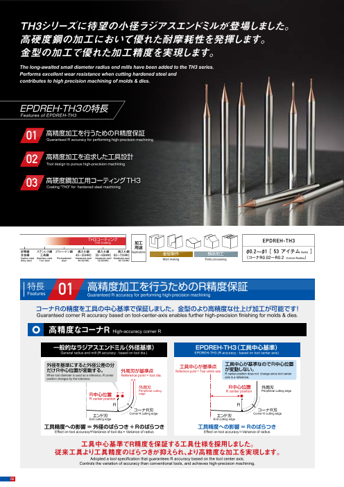
TH3シリーズに待望の小径ラジアスエンドミルが登場しました。高硬度鋼の加工において優れた耐摩耗性を発揮します。金型の加工で優れた加工精度を実現します。
このカタログについて
| ドキュメント名 | エポックディープラジアスエボリューションハード-TH3 |
|---|---|
| ドキュメント種別 | 製品カタログ |
| ファイルサイズ | 1.6Mb |
| 取り扱い企業 | 株式会社MOLDINO (この企業の取り扱いカタログ一覧) |
この企業の関連カタログ


このカタログの内容
Page1
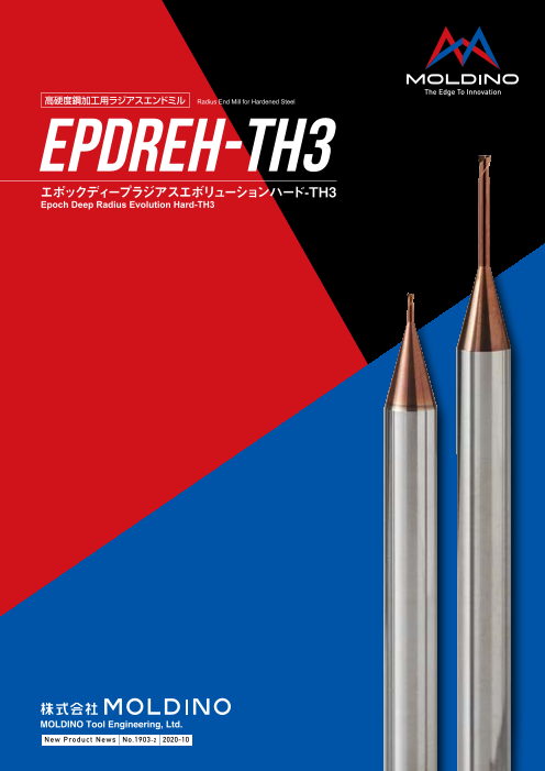
高硬度鋼加工用ラジアスエンドミル Radius End Mill for Hardened Steel
EPDREH-TH3
エポックディープラジアスエボリューションハード-TH3
Epoch Deep Radius Evolution Hard-TH3
図、表等のデータは試験結果の一例であり、保証値ではありません。
「 」は株式会社MOLDINOの登録商標です。
The diagrams and table data are examples of test results, and are not guaranteed values.
“ ” is a registered trademark of MOLDINO Tool Engineering, Ltd.
安 全 上 の ご 注 意 Attentions on Safety
1. 取扱上のご注意 1. Cautions regarding handling
(1)工具をケース(梱包)から取り出す際は、工具の飛び出し、落下にご注意ください。特に工具刃部との接 (1) When removing the tool from its case (packaging), be careful that the tool does not pop out or is
触には十分ご注意をお願いします。 dropped. Be particularly careful regarding contact with the tool flutes.
(2)鋭利な切れ刃を有する工具を取扱う際は、切れ刃を素手で直接触れないように注意してください。 (2) When handling tools with sharp cutting flutes, be careful not to touch the cutting flutes directly with
2. 取付け時のご注意 your bare hands.
(1)ご使用前に、工具の傷・割れ等の外観確認を行っていただき、コレットチャック等への取付けは確実に 2. Cautions regarding mounting
行ってください。 (1) Before use, check the outside appearance of the tool for scratches, cracks, etc. and that it is firmly
(2)ご使用中に、異常な振動等が発生した場合は、直ちに機械を停止させて、その振動の原因を取り除い mounted in the collet chuck, etc.
てください。 (2) If abnormal chattering, etc. occurs during use, stop the machine immediately and remove the cause
3. 使用上のご注意 of the chattering.
(1)切削工具あるいは被削材の寸法・回転の方向は、あらかじめ確認しておいてください。 3. Cautions during use
(2)標準切削条件表の数値は、新しい作業の立上げの目安としてご利用ください。切込みが大きい場合、 (1) Before use, confirm the dimensions and direction of rotation of the tool and milling work material.
使用機械の剛性が小さい場合あるいは被加工物の性状に応じて切削条件を適正に調整してご使用 (2) The numerical values in the standard cutting conditions table should be used as criteria when starting
ください。 new work. The cutting conditions should be adjusted as appropriate when the cutting depth is large,
(3)切削工具材料は硬質の材料です。ご使用中に破損して飛散する場合があります。また、切りくずが飛 the rigidity of the machine being used is low, or according to the conditions of the work material.
散することがあります。これらの飛散物等は作業者を切傷させ、火傷あるいは目に入って負傷させる恐 (3) Cutting tools are made of a hard material. During use, they may break and fly off. In addition, cutting
れがありますので、工具をご使用中はその周囲に安全カバーを取付け、保護めがね等の保護具を着用 chips may also fly off. Since there is a danger of injury to workers, fire, or eye damage from such
して安全な環境下での作業をお願いいたします。 flying pieces, a safety cover should be attached when work is performed and safety equipment such
(4)切削中に発生する火花や、破損による発熱や、切りくずによる引火・火災の危険があります。引火や as safety goggles should be worn to create a safe environment for work.
爆発の危険のあるところでは使用しないでください。不水溶性切削液をご使用される場合は防火対 (4) There is a risk of fire or inflammation due to sparks, heat due to breakage, and cutting chips. Do not
策を必ず行なってください。 use where there is a risk of fire or explosion. Please caution of fire while using oil base coolant, fire
(5)工具を本来の目的以外にはご使用にならないでください。 prevention is necessary.
4. 再研削時のご注意 (5) Do not use the tool for any purpose other than that for which it is intended.
(1)再研削時期が不適当であると工具が破損する恐れがあります。適正な工具と交換するか、再研削を 4. Cautions regarding regrinding
行ってください。
(2)工具を再研削しますと粉塵が発生します。再研削時にはその周囲に安全カバーを取付け、保護め (1) If regrinding is not performed at the proper time, there is a risk of the tool breaking. Replace the tool
がね等の保護具を着用してください。 with one in good condition, or perform regrinding.
(3)本製品には特定化学物質に指定された コバルト及びその無機化合物が含まれています。再研削等の (2) Grinding dust will be created when regrinding a tool. When regrinding, be sure to attach a safety
加工を加える場合は特定化学物質障害予防規則(特化則)に従った取扱いをしてください。 cover over the work area and wear safety clothes such as safety goggles, etc.(3) This product contains the specified chemical substance cobalt and its inorganic compounds. When
5. 工具に関して、安全上の問題点・不明の点・その他相談がありましたら フ リ ーダ イ ヤ ル 技 術 相 談 へ performing regrinding or similar processing, be sure to handle the processing in accordance with
ご相談ください。 thelocal laws and regulations regarding prevention of hazards due to specified chemical substances.
ホームページ フリーダイヤル技術相談
http://www.moldino.com
MOLDINO Tool Engineering, Ltd.
本社 〒130-0026 東京都墨田区両国4-31-11(ヒューリック両国ビル8階)
工具選定データベース【 TOOL SEARCH】
03-6890-5101 FAX 03-6890-5134
International Sales Dept .: +81-3-6890-5103 FAX +81-3-6890-5128
営業企画部 ☎03-6890-5102 FAX03-6890-5134 海外営業部 ☎03-6890-5103 FAX03-6890-5128
東京営業所 ☎03-6890-5110 FAX03-6890-5133 静岡営業所 ☎054-273-0360 FAX054-273-0361
東北営業所 ☎022-208-5100 FAX022-208-5102 名古屋営業所 ☎052-687-9150 FAX052-687-9144
新潟営業所 ☎0258-87-1224 FAX0258-87-1158 大阪営業所 ☎06-7668-0190 FAX06-7668-0194
東関東営業所 ☎0294-88-9430 FAX0294-88-9432 中四営業所 ☎082-536-2001 FAX082-536-2003
長野営業所 ☎0268-21-3700 FAX0268-21-3711 九州営業所 ☎092-289-7010 FAX092-289-7012
北関東営業所 ☎0276-59-6001 FAX0276-59-6005 北九州営業所 ☎093-434-2640 FAX093-434-6846
神奈川営業所 ☎046-400-9429 FAX046-400-9435
ヨーロッパ/MOLDINO Tool Engineering Europe GmbH Itterpark 12, 40724 Hilden, Germany. TEL : +49-(0)2103-24820, FAX : +49-(0)2103-248230
中 国/MOLDINO Tool Engineering, (Shanghai) Ltd. Room 2604-2605, Metro Plaza, 555 Loushanguan Road, Changning Disctrict, Shanghai, 200051, CHINA TEL:+86-(0)21-3366-3058, FAX:+86-(0)21-3366-3050
アメリカ/MITSUBISHI MATERIALS U.S.A. CORPORATION 41700 Gardenbrook Road, Suite 120, Novi, MI 48375-1320 U.S.A. TEL : +1(248)308-2620, FAX :+1(248)308-2627
メキシコ/MMC METAL DE MEXICO, S.A. DE C.V. Av. La Cañada No.16, Parque Industrial Bernardo Quintana, El Marques, Querétaro, CP 76246, México TEL : +52-442-1926800 MOLDINO Tool Engineering, Ltd.
ブラジル/MMC METAL DO BRASIL LTDA. Rua Cincinato Braga, 340 13° andar.Bela Vista – CEP 01333-010 São Paulo – SP ., Brasil TEL : +55(11)3506-5600 FAX : +55(11)3506-5677
タ イ/MMC Hardmetal (Thailand) Co.,Ltd. MOLDINO Division 622 Emporium Tower, Floor 22/1-4, Sukhumvit Road, Klong Tan, Klong Toei, Bangkok 10110, Thailand TEL:+66-(0)2-661-8175 FAX:+66-(0)2-661-8176
イ ン ド/Hitachi Metals (India) Pvt. Ltd. Plot No 94 & 95,Sector 8, IMT Manesar, Gurgaon -122050, Haryana, India TEL : +91-124-4812315, FAX :+91-124-2290015 New Produc t News No.1903-2 2020-10
掲載価格は消費税抜きの単価を表示しております。予告なく、改良・改善のために仕様変更することがあります。
Specifications for the products listed in this catalog are subject to change without notice due to ベジタブルインクで印刷しています。 2020-10(K)
replacement or modification. Printed using vegetable oil ink. Printed in JAPAN 2019-5:FP
Page2
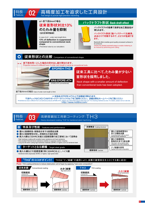
TH3シリーズに待望の小径ラジアスエンドミルが登場しました。 特長 02 高精度加工を追求した工具設計高硬度鋼の加工において優れた耐摩耗性を発揮します。 Features Tool design to pursue high-precision machining
金型の加工で優れた加工精度を実現します。 φ1-首下長8mmの場合 バックドラフト形状 Back draft effect
従来首形状対比13%
The long-awaited small diameter radius end mills have been added to the TH3 series. バックドラフトの効果で良好な加工面品位が
Performs excellent wear resistance when cutting hardened steel and のたわみ量を抑制 得られます。
contributes to high precision machining of molds & dies. (当社計算理論値) バックドラフト形状(強バックテーパ)を継承。
In case of φ1 - under neck length 8mm, 点あたりで切削するので、ビビりが低減でき
13% of deflection is suppressed ます。
compared to conventional neck Backdraft effect enables good-quality processed surfaces to
EPDREH-TH3の特長 shape
be achieved.
Inherits the reliable backdraft shape to enable chattering to
(Theoretical value by our calculation) be reduced by performing point cutting.
Features of EPDREH-TH3
01 高精度加工を行うためのR精度保証 従来形状との比較 Comparison of conventional shapeGuaranteed R accuracy for performing high-precision machining
首下長を同一とした場合の突き出し量が異なります。
02 高精度加工を追求した工具設計 Projection amount is different even if under neck length is same as conventional tools.Tool design to pursue high-precision machining EPDREH-TH3
従来工具に比べて、たわみ量が少ない
03 高硬度鋼加工用コーティング TH3 首形状を採用しました。Coating "TH3" for hardened steel machining
従来品EPDRE-ATH Neck shape with a smaller amount of deflection
EPDRE-ATH (conventional)
than conventional tools has been adopted.
首下長4mmの場合 Case of under neck length is 4mm
⇒ 従来品(EPDRE-ATH)と干渉領域が異なります。
干渉チェックはCAD/CAMサポートデータパックVol.7をご使用ください。詳細は弊社ホームページをご覧ください
TH3コーティング EPDREH-TH3 ⇒Interference area is different from conventional products (EPDRE-ATH). Please use CAD/CAM Support Data Pack Vol.7 for checking interference area. For details, please visit our web site.TH3 Coating 加工 http://www.moldino.com/
用途
炭素鋼 ステンレス鋼 プリハードン鋼 焼入れ鋼 焼入れ鋼 焼入れ鋼 Applications φ0.2~φ1[ 53 アイテム Items ]
合金鋼 工具鋼 45~55HRC 55~65HRC 65~72HRC 金型製作 部品加工
Carbon steel Stainless steel Pre-hardened Hardened steel Hardened steel Hardened steel Mold making Parts processing (コーナR0.02~R0.2 Corner Radius)Alloy steel Tool steel steel 45̃55HRC 55̃65HRC 65̃72HRC
特長 高硬度鋼加工用新コーティング TH3
特長 01 高精度加工を行うためのR精度保証 Features 03 Newly developed coating "TH3" for hardened steel machiningFeatures Guaranteed R accuracy for performing high-precision machining
特長及び性能 Features and performance 皮膜構造 Coating structure
コーナRの精度を工具の中心基準で保証しました。金型のより高精度な仕上げ加工が可能です!
Guaranteed corner R accuracy based on tool-center-axis enables further high-precision finishing for molds & dies. ● 優れた耐摩耗性・耐熱性を有する高硬度皮膜
優れた耐熱衝撃性を
● 優れた耐衝撃性を有し、突発的な欠損を抑制 有する機能皮膜Funcitional layer with excellent
● 焼入れ鋼など50HRCを超える高硬度鋼の加工領域において長寿命 thermal shock resistance
高精度なコーナR High-accuracy corner R ・High hardness coating with excellent wear resistance and heat resistance 優れた耐摩耗性、
・Has excellent thermal shock resistance enables to suppress sudden chipping 耐熱性を有する新皮膜
・Long tool life when cutting high-hardness materials (50HRC or higher) such as hardened steel New layer with excellent wear
resistance and heat resistance
一般的なラジアスエンドミル(外径基準) EPDREH-TH3(工具中心基準) ターゲットとなる鋼種 Target steel grade
General radius end mill (R accuracy : based on tool dia.) EPDREH-TH3 (R accuracy : based on tool center axis) ナノ組織を採用Applies nano-size composition
● 焼入れ鋼などの高硬度鋼(特に50HRC以上)、ハイス鋼 超硬母材 Carbide
外径を基準にすると外径公差の分 工具中心が基準点 工具中心が基準なのでR中心位置 ・Hardened steel (especially 50HRC or higher), high-speed steel
だけR中心位置が変動する。 外周刃が基準点 Reference point = Tool center axis が変動しない。
When tool diameter is used as a reference, R center Reference point = tool dia. R center position does not change since tool center
position changes by the tolerance. axis is a reference. ! “TH3”のココがポイント! TH3は“ナノ組織”の適用により、皮膜の破壊単位を小さくする事に成功!
外周刃 R中心位置 外周刃
Peripheral cutting R center position Peripheral cutting edge Point TH3 coating achieves to reduce destruction unit of layer by applying "nano-size composition".
R中心位置 edge
R center position 従来皮膜 Conventional coating 大きく破壊 T H 3 TH3 coating
R R Big destruction
コーナR刃 コーナR刃 切削抵抗 切削抵抗 小さく破壊Small destruction
エンド刃
Corner R cutting edge
エンド刃
Corner R cutting edge Cutting force Cutting force
End cutting edge End cutting edge
工具精度への影響=外径のばらつき+Rのばらつき 工具精度への影響=Rのばらつき
Effect on tool accuracy=Variance of tool dia.+ Variance of radius Effect on tool accuracy=Variance of radius
工具中心基準でR精度を保証する工具仕様を採用しました。
従来工具より工具精度のばらつきが抑えられ、より高精度な加工を実現します。 超硬母材 Carbide 超硬母材 Carbide 超硬母材 Carbide 超硬母材 Carbide
Adopted a tool specification that guarantees R accuracy based on the tool center axis.
Controls the variation of accuracy than conventional tools, and achieves high-precision machining.
02 03
Page3
TH3シリーズに待望の小径ラジアスエンドミルが登場しました。 特長 02 高精度加工を追求した工具設計高硬度鋼の加工において優れた耐摩耗性を発揮します。 Features Tool design to pursue high-precision machining
金型の加工で優れた加工精度を実現します。 φ1-首下長8mmの場合 バックドラフト形状 Back draft effect
従来首形状対比13%
The long-awaited small diameter radius end mills have been added to the TH3 series. バックドラフトの効果で良好な加工面品位が
Performs excellent wear resistance when cutting hardened steel and のたわみ量を抑制 得られます。
contributes to high precision machining of molds & dies. (当社計算理論値) バックドラフト形状(強バックテーパ)を継承。
In case of φ1 - under neck length 8mm, 点あたりで切削するので、ビビりが低減でき
13% of deflection is suppressed ます。
compared to conventional neck Backdraft effect enables good-quality processed surfaces to
EPDREH-TH3の特長 shape
be achieved.
Inherits the reliable backdraft shape to enable chattering to
(Theoretical value by our calculation) be reduced by performing point cutting.
Features of EPDREH-TH3
01 高精度加工を行うためのR精度保証 従来形状との比較 Comparison of conventional shapeGuaranteed R accuracy for performing high-precision machining
首下長を同一とした場合の突き出し量が異なります。
02 高精度加工を追求した工具設計 Projection amount is different even if under neck length is same as conventional tools.Tool design to pursue high-precision machining EPDREH-TH3
従来工具に比べて、たわみ量が少ない
03 高硬度鋼加工用コーティング TH3 首形状を採用しました。Coating "TH3" for hardened steel machining
従来品EPDRE-ATH Neck shape with a smaller amount of deflection
EPDRE-ATH (conventional)
than conventional tools has been adopted.
首下長4mmの場合 Case of under neck length is 4mm
⇒ 従来品(EPDRE-ATH)と干渉領域が異なります。
干渉チェックはCAD/CAMサポートデータパックVol.7をご使用ください。詳細は弊社ホームページをご覧ください
TH3コーティング EPDREH-TH3 ⇒Interference area is different from conventional products (EPDRE-ATH). Please use CAD/CAM Support Data Pack Vol.7 for checking interference area. For details, please visit our web site.TH3 Coating 加工 http://www.moldino.com/
用途
炭素鋼 ステンレス鋼 プリハードン鋼 焼入れ鋼 焼入れ鋼 焼入れ鋼 Applications φ0.2~φ1[ 53 アイテム Items ]
合金鋼 工具鋼 45~55HRC 55~65HRC 65~72HRC 金型製作 部品加工
Carbon steel Stainless steel Pre-hardened Hardened steel Hardened steel Hardened steel Mold making Parts processing (コーナR0.02~R0.2 Corner Radius)Alloy steel Tool steel steel 45̃55HRC 55̃65HRC 65̃72HRC
特長 高硬度鋼加工用新コーティング TH3
特長 01 高精度加工を行うためのR精度保証 Features 03 Newly developed coating "TH3" for hardened steel machiningFeatures Guaranteed R accuracy for performing high-precision machining
特長及び性能 Features and performance 皮膜構造 Coating structure
コーナRの精度を工具の中心基準で保証しました。金型のより高精度な仕上げ加工が可能です!
Guaranteed corner R accuracy based on tool-center-axis enables further high-precision finishing for molds & dies. ● 優れた耐摩耗性・耐熱性を有する高硬度皮膜
優れた耐熱衝撃性を
● 優れた耐衝撃性を有し、突発的な欠損を抑制 有する機能皮膜Funcitional layer with excellent
● 焼入れ鋼など50HRCを超える高硬度鋼の加工領域において長寿命 thermal shock resistance
高精度なコーナR High-accuracy corner R ・High hardness coating with excellent wear resistance and heat resistance 優れた耐摩耗性、
・Has excellent thermal shock resistance enables to suppress sudden chipping 耐熱性を有する新皮膜
・Long tool life when cutting high-hardness materials (50HRC or higher) such as hardened steel New layer with excellent wear
resistance and heat resistance
一般的なラジアスエンドミル(外径基準) EPDREH-TH3(工具中心基準) ターゲットとなる鋼種 Target steel grade
General radius end mill (R accuracy : based on tool dia.) EPDREH-TH3 (R accuracy : based on tool center axis) ナノ組織を採用Applies nano-size composition
● 焼入れ鋼などの高硬度鋼(特に50HRC以上)、ハイス鋼 超硬母材 Carbide
外径を基準にすると外径公差の分 工具中心が基準点 工具中心が基準なのでR中心位置 ・Hardened steel (especially 50HRC or higher), high-speed steel
だけR中心位置が変動する。 外周刃が基準点 Reference point = Tool center axis が変動しない。
When tool diameter is used as a reference, R center Reference point = tool dia. R center position does not change since tool center
position changes by the tolerance. axis is a reference. ! “TH3”のココがポイント! TH3は“ナノ組織”の適用により、皮膜の破壊単位を小さくする事に成功!
外周刃 R中心位置 外周刃
Peripheral cutting R center position Peripheral cutting edge Point TH3 coating achieves to reduce destruction unit of layer by applying "nano-size composition".
R中心位置 edge
R center position 従来皮膜 Conventional coating 大きく破壊 T H 3 TH3 coating
R R Big destruction
コーナR刃 コーナR刃 切削抵抗 切削抵抗 小さく破壊Small destruction
エンド刃
Corner R cutting edge
エンド刃
Corner R cutting edge Cutting force Cutting force
End cutting edge End cutting edge
工具精度への影響=外径のばらつき+Rのばらつき 工具精度への影響=Rのばらつき
Effect on tool accuracy=Variance of tool dia.+ Variance of radius Effect on tool accuracy=Variance of radius
工具中心基準でR精度を保証する工具仕様を採用しました。
従来工具より工具精度のばらつきが抑えられ、より高精度な加工を実現します。 超硬母材 Carbide 超硬母材 Carbide 超硬母材 Carbide 超硬母材 Carbide
Adopted a tool specification that guarantees R accuracy based on the tool center axis.
Controls the variation of accuracy than conventional tools, and achieves high-precision machining.
02 03
Page4
ラインナップ
Line Up
ラジアス Radius コーナR公差:±0.005mm(中心基準)Tolerance on Corner radius (Central axis)
r θκ 【注意】
2枚刃 φDc エポックディープラジアスエボリュ-ション
実有効
首下長
2 Flutes EPDRE-ATHとは勾配角に対する実有
効首下長が異なります。
The effective
R 15° under-neck
R2
L
再度ご確認お願いいたします。 length
勾配角
【Note】 Draft 干渉角度θκ
The actual effective length in incline angles is angle Interference
different from Epoch Deep Radius Evolution
72 ねじれ30° h5
angle
EPDREH2 - . - -TH3
TH3 EPDRE-ATH.
HRC - - - Please recheck the interference area.
Carbide TH3-coated Helix angle EPDREH2 . TH3
寸 法 Size(mm) 干渉角度 勾配角に対する実有効首下長 希望小売 寸 法 Size(mm) 干渉角度 勾配角に対する実有効首下長 希望小売
商品コード 在庫 外径 コーナR 首下長 刃長 首径 全長 シャンク径 θκ Actual effective length 価格(円) 商品コード 在庫 外径 コーナR 首下長 刃長 首径 全長 シャンク径 θκ Actual effective length 価格(円)
Dc r R2 R D1 L Ds Interference in incline angles Suggested Interference in incline anglesItem code Stock angle Item code Stock Dc r R2 R D1 L Ds angle Suggested
Tool Corner Under neck Flute Neck Overall Shank retail price Tool Corner Under neck Flute Neck Overall Shank retail price
dia. radius length length dia. length dia. (°) 0.5° 1° 1.5° 2° 3° (¥) dia. radius length length dia. length dia. (°) 0.5° 1° 1.5° 2° 3° (¥)
EPDREH2002-0.5-002-TH3 ● 0.5 13.99 0.57 0.59 0.61 0.63 0.68 10,100 EPDREH2010-2-002-TH3 ● 2 11.04 2.18 2.25 2.33 2.42 2.62 5,170
0.02
EPDREH2002-1-002-TH3 ● 1 13.16 1.09 1.12 1.16 1.21 1.3 10,100 EPDREH2010-4-002-TH3 ● 4 8.8 4.24 4.39 4.55 4.72 5.1 5,170
0.2 0.15 0.17 50 4 0.02
EPDREH2002-0.5-005-TH3 ● 0.5 14.05 0.57 0.59 0.61 0.63 0.67 10,100 EPDREH2010-6-002-TH3 ● 6 7.32 6.31 6.53 6.77 7.02 7.59 5,610
0.05
EPDREH2002-1-005-TH3 ● 1 13.21 1.08 1.12 1.16 1.2 1.3 10,100 EPDREH2010-8-002-TH3 ● 8 6.26 8.38 8.67 8.98 9.32 10.07 5,610
EPDREH2003-1-002-TH3 ● 1 13.12 1.09 1.12 1.16 1.21 1.3 9,770 EPDREH2010-2-005-TH3 ● 2 11.08 2.18 2.25 2.33 2.42 2.61 5,170
0.02
EPDREH2003-2-002-TH3 ● 2 11.7 2.12 2.19 2.27 2.36 2.55 9,770 EPDREH2010-4-005-TH3 ● 4 8.83 4.24 4.39 4.55 4.72 5.09 5,170
0.3 0.25 0.27 50 4 0.05
EPDREH2003-1-005-TH3 ● 1 13.17 1.08 1,12 1.16 1.2 1.3 9,770 EPDREH2010-6-005-TH3 ● 6 7.34 6.31 6.53 6.76 7.02 7.58 5,610
0.05
EPDREH2003-2-005-TH3 ● 2 11.73 2.12 2.19 2.27 2.35 2.54 9,770 EPDREH2010-8-005-TH3 ● 8 6.27 8.38 8.67 8.98 9.32 10.07 5,610
1 0.8 0.94 50 4
EPDREH2004-1-002-TH3 ● 1 13.07 1.09 1.12 1.16 1.21 1.3 6,510 EPDREH2010-2-01-TH3 ● 2 11.16 2.17 2.25 2.33 2.41 2.6 5,170
0.02
EPDREH2004-2-002-TH3 ● 2 11.62 2.12 2.19 2.27 2.36 2.55 6,510 EPDREH2010-4-01-TH3 ● 4 8.88 4.24 4.39 4.54 4.71 5.08 5,170
0.1
EPDREH2004-1-005-TH3 ● 1 13.12 1.08 1.12 1.16 1.2 1.3 6,510 EPDREH2010-6-01-TH3 ● 6 7.37 6.31 6.53 6.76 7.01 7.57 5,610
0.4 0.05 0.3 0.37 50 4
EPDREH2004-2-005-TH3 ● 2 11.66 2.12 2.19 2.27 2.35 2.54 6,510 EPDREH2010-8-01-TH3 ● 8 6.29 8.38 8.67 8.97 9.31 10.06 5,610
EPDREH2004-1-01-TH3 ● 1 13.21 1.08 1.12 1.15 1.19 1.28 6,510 EPDREH2010-2-02-TH3 ● 2 11.3 2.17 2.24 2.31 2.39 2.57 5,170
0.1
EPDREH2004-2-01-TH3 ● 2 11.73 2.12 2.19 2.26 2.34 2.53 6,510 EPDREH2010-4-02-TH3 ● 4 8.97 4.24 4.38 4.53 4.69 5.06 5,170
0.2
EPDREH2005-1-002-TH3 ● 1 13.03 1.09 1.12 1.16 1.21 1.3 5,280 EPDREH2010-6-02-TH3 ● 6 7.43 6.31 6.52 6.75 6.99 7.55 5,610
EPDREH2005-2-002-TH3 ● 0.02 2 11.55 2.12 2.19 2.27 2.36 2.55 5,280 EPDREH2010-8-02-TH3 ● 8 6.34 8.37 8.66 8.96 9.29 10.03 5,610
EPDREH2005-3-002-TH3 ● 3 10.37 3.15 3.26 3.38 3.51 3.79 5,280
EPDREH2005-1-005-TH3 ● 1 13.08 1.08 1.12 1.16 1.2 1.3 5,280
EPDREH2005-2-005-TH3 ● 0.5 0.05 2 0.35 0.47 50 4 11.59 2.12 2.19 2.27 2.35 2.54 5,280
EPDREH2005-3-005-TH3 ● 3 10.4 3.15 3.26 3.38 3.5 3.78 5,280
EPDREH2005-1-01-TH3 ● 1 13.16 1.08 1.12 1.15 1.19 1.28 5,280
EPDREH2005-2-01-TH3 ● 0.1 2 11.66 2.12 2.19 2.26 2.34 2.53 5,280
EPDREH2005-3-01-TH3 ● 3 10.46 3.15 3.26 3.37 3.49 3.77 5,280
EPDREH2006-2-002-TH3 ● 2 11.47 2.12 2.19 2.27 2.36 2.55 5,280
0.02
EPDREH2006-4-002-TH3 ● 4 9.31 4.19 4.33 4.49 4.66 5.03 5,280
EPDREH2006-2-005-TH3 ● 2 11.51 2.12 2.19 2.27 2.35 2.54 5,280
0.6 0.05 0.4 0.57 50 4
EPDREH2006-4-005-TH3 ● 4 9.33 4.19 4.33 4.48 4.65 5.03 5,280
EPDREH2006-2-01-TH3 ● 2 11.58 2.12 2.19 2.26 2.34 2.53 5,280
0.1
EPDREH2006-4-01-TH3 ● 4 9.38 4.18 4.33 4.48 4.64 5.01 5,280
EPDREH2008-2-002-TH3 ● 2 11.3 2.12 2.19 2.27 2.36 2.55 6,060
0.02
EPDREH2008-4-002-TH3 ● 4 9.09 4.19 4.33 4.49 4.66 5.03 6,060
EPDREH2008-2-005-TH3 ● 2 11.35 2.12 2.19 2.27 2.35 2.54 6,060
0.05
EPDREH2008-4-005-TH3 ● 4 9.12 4.19 4.33 4.48 4.65 5.03 6,060
0.8 0.5 0.77 50 4
EPDREH2008-2-01-TH3 ● 2 11.42 2.12 2.19 2.26 2.34 2.53 6,060
0.1
EPDREH2008-4-01-TH3 ● 4 9.16 4.18 4.33 4.48 4.64 5.01 6,060
EPDREH2008-2-02-TH3 ● 2 11.56 2.11 2.18 2.25 2.33 2.5 6,060
0.2
EPDREH2008-4-02-TH3 ● 4 9.25 4.18 4.32 4.47 4.63 4.99 6,060
再研磨対応範囲一覧表 Re-grinding compatibility range table
商品コード 商品名称 形 状
再研磨対応外径範囲(㎜)
Re-grinding compatibility range
Item Code Product Name Shape 外周 Outer Dia. エンド End
EPDREH-TH3 エポックディープラジアスエボリューションハード-TH3Epoch Deep Radius Evolution Hard-TH3 × ×
●印:標準在庫品です。 ●:Stocked Items.
04 05
φD1
φDs
Page5
ラインナップ
Line Up
ラジアス Radius コーナR公差:±0.005mm(中心基準)Tolerance on Corner radius (Central axis)
r θκ 【注意】
2枚刃 φDc エポックディープラジアスエボリュ-ション
実有効
首下長
2 Flutes EPDRE-ATHとは勾配角に対する実有
効首下長が異なります。
The effective
R 15° under-neck
R2
L
再度ご確認お願いいたします。 length
勾配角
【Note】 Draft 干渉角度θκ
The actual effective length in incline angles is angle Interference
different from Epoch Deep Radius Evolution
72 ねじれ30° h5
angle
EPDREH2 - . - -TH3
TH3 EPDRE-ATH.
HRC - - - Please recheck the interference area.
Carbide TH3-coated Helix angle EPDREH2 . TH3
寸 法 Size(mm) 干渉角度 勾配角に対する実有効首下長 希望小売 寸 法 Size(mm) 干渉角度 勾配角に対する実有効首下長 希望小売
商品コード 在庫 外径 コーナR 首下長 刃長 首径 全長 シャンク径 θκ Actual effective length 価格(円) 商品コード 在庫 外径 コーナR 首下長 刃長 首径 全長 シャンク径 θκ Actual effective length 価格(円)
Dc r R2 R D1 L Ds Interference in incline angles Suggested Interference in incline anglesItem code Stock angle Item code Stock Dc r R2 R D1 L Ds angle Suggested
Tool Corner Under neck Flute Neck Overall Shank retail price Tool Corner Under neck Flute Neck Overall Shank retail price
dia. radius length length dia. length dia. (°) 0.5° 1° 1.5° 2° 3° (¥) dia. radius length length dia. length dia. (°) 0.5° 1° 1.5° 2° 3° (¥)
EPDREH2002-0.5-002-TH3 ● 0.5 13.99 0.57 0.59 0.61 0.63 0.68 10,100 EPDREH2010-2-002-TH3 ● 2 11.04 2.18 2.25 2.33 2.42 2.62 5,170
0.02
EPDREH2002-1-002-TH3 ● 1 13.16 1.09 1.12 1.16 1.21 1.3 10,100 EPDREH2010-4-002-TH3 ● 4 8.8 4.24 4.39 4.55 4.72 5.1 5,170
0.2 0.15 0.17 50 4 0.02
EPDREH2002-0.5-005-TH3 ● 0.5 14.05 0.57 0.59 0.61 0.63 0.67 10,100 EPDREH2010-6-002-TH3 ● 6 7.32 6.31 6.53 6.77 7.02 7.59 5,610
0.05
EPDREH2002-1-005-TH3 ● 1 13.21 1.08 1.12 1.16 1.2 1.3 10,100 EPDREH2010-8-002-TH3 ● 8 6.26 8.38 8.67 8.98 9.32 10.07 5,610
EPDREH2003-1-002-TH3 ● 1 13.12 1.09 1.12 1.16 1.21 1.3 9,770 EPDREH2010-2-005-TH3 ● 2 11.08 2.18 2.25 2.33 2.42 2.61 5,170
0.02
EPDREH2003-2-002-TH3 ● 2 11.7 2.12 2.19 2.27 2.36 2.55 9,770 EPDREH2010-4-005-TH3 ● 4 8.83 4.24 4.39 4.55 4.72 5.09 5,170
0.3 0.25 0.27 50 4 0.05
EPDREH2003-1-005-TH3 ● 1 13.17 1.08 1,12 1.16 1.2 1.3 9,770 EPDREH2010-6-005-TH3 ● 6 7.34 6.31 6.53 6.76 7.02 7.58 5,610
0.05
EPDREH2003-2-005-TH3 ● 2 11.73 2.12 2.19 2.27 2.35 2.54 9,770 EPDREH2010-8-005-TH3 ● 8 6.27 8.38 8.67 8.98 9.32 10.07 5,610
1 0.8 0.94 50 4
EPDREH2004-1-002-TH3 ● 1 13.07 1.09 1.12 1.16 1.21 1.3 6,510 EPDREH2010-2-01-TH3 ● 2 11.16 2.17 2.25 2.33 2.41 2.6 5,170
0.02
EPDREH2004-2-002-TH3 ● 2 11.62 2.12 2.19 2.27 2.36 2.55 6,510 EPDREH2010-4-01-TH3 ● 4 8.88 4.24 4.39 4.54 4.71 5.08 5,170
0.1
EPDREH2004-1-005-TH3 ● 1 13.12 1.08 1.12 1.16 1.2 1.3 6,510 EPDREH2010-6-01-TH3 ● 6 7.37 6.31 6.53 6.76 7.01 7.57 5,610
0.4 0.05 0.3 0.37 50 4
EPDREH2004-2-005-TH3 ● 2 11.66 2.12 2.19 2.27 2.35 2.54 6,510 EPDREH2010-8-01-TH3 ● 8 6.29 8.38 8.67 8.97 9.31 10.06 5,610
EPDREH2004-1-01-TH3 ● 1 13.21 1.08 1.12 1.15 1.19 1.28 6,510 EPDREH2010-2-02-TH3 ● 2 11.3 2.17 2.24 2.31 2.39 2.57 5,170
0.1
EPDREH2004-2-01-TH3 ● 2 11.73 2.12 2.19 2.26 2.34 2.53 6,510 EPDREH2010-4-02-TH3 ● 4 8.97 4.24 4.38 4.53 4.69 5.06 5,170
0.2
EPDREH2005-1-002-TH3 ● 1 13.03 1.09 1.12 1.16 1.21 1.3 5,280 EPDREH2010-6-02-TH3 ● 6 7.43 6.31 6.52 6.75 6.99 7.55 5,610
EPDREH2005-2-002-TH3 ● 0.02 2 11.55 2.12 2.19 2.27 2.36 2.55 5,280 EPDREH2010-8-02-TH3 ● 8 6.34 8.37 8.66 8.96 9.29 10.03 5,610
EPDREH2005-3-002-TH3 ● 3 10.37 3.15 3.26 3.38 3.51 3.79 5,280
EPDREH2005-1-005-TH3 ● 1 13.08 1.08 1.12 1.16 1.2 1.3 5,280
EPDREH2005-2-005-TH3 ● 0.5 0.05 2 0.35 0.47 50 4 11.59 2.12 2.19 2.27 2.35 2.54 5,280
EPDREH2005-3-005-TH3 ● 3 10.4 3.15 3.26 3.38 3.5 3.78 5,280
EPDREH2005-1-01-TH3 ● 1 13.16 1.08 1.12 1.15 1.19 1.28 5,280
EPDREH2005-2-01-TH3 ● 0.1 2 11.66 2.12 2.19 2.26 2.34 2.53 5,280
EPDREH2005-3-01-TH3 ● 3 10.46 3.15 3.26 3.37 3.49 3.77 5,280
EPDREH2006-2-002-TH3 ● 2 11.47 2.12 2.19 2.27 2.36 2.55 5,280
0.02
EPDREH2006-4-002-TH3 ● 4 9.31 4.19 4.33 4.49 4.66 5.03 5,280
EPDREH2006-2-005-TH3 ● 2 11.51 2.12 2.19 2.27 2.35 2.54 5,280
0.6 0.05 0.4 0.57 50 4
EPDREH2006-4-005-TH3 ● 4 9.33 4.19 4.33 4.48 4.65 5.03 5,280
EPDREH2006-2-01-TH3 ● 2 11.58 2.12 2.19 2.26 2.34 2.53 5,280
0.1
EPDREH2006-4-01-TH3 ● 4 9.38 4.18 4.33 4.48 4.64 5.01 5,280
EPDREH2008-2-002-TH3 ● 2 11.3 2.12 2.19 2.27 2.36 2.55 6,060
0.02
EPDREH2008-4-002-TH3 ● 4 9.09 4.19 4.33 4.49 4.66 5.03 6,060
EPDREH2008-2-005-TH3 ● 2 11.35 2.12 2.19 2.27 2.35 2.54 6,060
0.05
EPDREH2008-4-005-TH3 ● 4 9.12 4.19 4.33 4.48 4.65 5.03 6,060
0.8 0.5 0.77 50 4
EPDREH2008-2-01-TH3 ● 2 11.42 2.12 2.19 2.26 2.34 2.53 6,060
0.1
EPDREH2008-4-01-TH3 ● 4 9.16 4.18 4.33 4.48 4.64 5.01 6,060
EPDREH2008-2-02-TH3 ● 2 11.56 2.11 2.18 2.25 2.33 2.5 6,060
0.2
EPDREH2008-4-02-TH3 ● 4 9.25 4.18 4.32 4.47 4.63 4.99 6,060
再研磨対応範囲一覧表 Re-grinding compatibility range table
商品コード 商品名称 形 状
再研磨対応外径範囲(㎜)
Re-grinding compatibility range
Item Code Product Name Shape 外周 Outer Dia. エンド End
EPDREH-TH3 エポックディープラジアスエボリューションハード-TH3Epoch Deep Radius Evolution Hard-TH3 × ×
●印:標準在庫品です。 ●:Stocked Items.
04 05
φD1
φDs
Page6
標準切削条件表
Recommended Cut t ing Condi t ions
高能率切削条件 高精度切削条件
High efficiency cuttiing condition High accuracy cuttiing condition 高精度切削条件は8ページを参照してください。Please refer to P.8 about high accuracy cutting conditions
1 2 3 4 5 1 2 3 4 5
被削材 プリハードン鋼 焼入れ鋼 焼入れ鋼 焼入れ鋼 焼入れ鋼 被削材 プリハードン鋼 焼入れ鋼 焼入れ鋼 焼入れ鋼 焼入れ鋼
Work material Pre-hardened Steels Hardened Steels Hardened Steels Hardened Steels Hardened Steels Work material Pre-hardened Steels Hardened Steels Hardened Steels Hardened Steels Hardened Steels
(35~45HRC) (45~55HRC) (55~65HRC) (65~68HRC) (68~72HRC) (35~45HRC) (45~55HRC) (55~65HRC) (65~68HRC) (68~72HRC)
切り込み比率 Ratio to standard depth of cut 100% 85% 80% 65% 55% 切り込み比率 Ratio to standard depth of cut 100% 85% 80% 65% 55%
外径Dc コーナR 首下長 ap 回転数 送り速度 回転数 送り速度 回転数 送り速度 回転数 送り速度 回転数 送り速度 外径Dc コーナR 首下長 ap 回転数 送り速度 回転数 送り速度 回転数 送り速度 回転数 送り速度 回転数 送り速度
Tool dia. Corner radius Under necklength (mm) n v f n v f n v f n v f n v f Tool dia. Corner radius Under neck
(mm) (mm)
length (mm) n v f n v f n v f n v f n v f
(mm) min-1 mm/min min-1 mm/min min-1 mm/min min-1 mm/min min-1 mm/min (mm) (mm) (mm) min-1 mm/min min-1 mm/min min-1 mm/min min-1 mm/min min-1 mm/min
0.5 0.016 42,500 710 37,500 550 35,000 450 31,500 410 31,880 320 2 0.016 33,440 1,810 29,620 1,420 27,710 1,160 24,940 1,050 25,170 810
0.02
1 0.011 42,500 710 37,500 550 35,000 450 31,500 410 31,880 320 4 0.013 30,600 1,650 27,000 1,290 25,200 1,060 22,680 950 22,950 740
0.2 0.02
0.5 0.02 42,500 710 37,500 550 35,000 450 31,500 410 31,880 320 6 0.01 24,790 1,340 21,870 1,050 20,410 860 18,370 770 18,590 600
0.05
1 0.014 42,500 710 37,500 550 35,000 450 31,500 410 31,880 320 8 0.008 22,030 1,190 19,440 930 18,140 760 16,330 680 16,520 530
1 0.016 40,800 730 36,000 550 33,600 440 30,240 400 30,600 310 2 0.046 33,440 1,810 29,620 1,420 27,710 1,160 24,940 1,050 25,170 810
0.02
2 0.011 33,050 590 29,160 440 27,220 360 24,490 320 24,790 250 4 0.027 30,600 1,650 27,000 1,290 25,200 1,060 22,680 950 22,950 740
0.3 0.05
1 0.021 40,800 730 36,000 550 33,600 440 30,240 400 30,600 310 6 0.017 24,790 1,340 21,870 1,050 20,410 860 18,370 770 18,590 600
0.05
2 0.012 33,050 590 29,160 440 27,220 360 24,490 320 24,790 250 8 0.016 22,030 1,190 19,440 930 18,140 760 16,330 680 16,520 530
1
1 0.016 32,260 790 28,800 620 26,730 510 24,050 460 24,480 360 2 0.065 33,440 1,810 29,620 1,420 27,710 1,160 24,940 1,050 25,170 810
0.02
2 0.013 32,260 710 28,800 560 26,730 460 24,050 410 24,480 320 4 0.038 30,600 1,650 27,000 1,290 25,200 1,060 22,680 950 22,950 740
0.1
1 0.025 32,260 790 28,800 620 26,730 510 24,050 460 24,480 360 6 0.024 24,790 1,340 21,870 1,050 20,410 860 18,370 770 18,590 600
0.4 0.05
2 0.016 32,260 710 28,800 560 26,730 460 24,050 410 24,480 320 8 0.024 22,030 1,190 19,440 930 18,140 760 16,330 680 16,520 530
1 0.033 32,260 790 28,800 620 26,730 510 24,050 460 24,480 360 2 0.11 33,440 1,810 29,620 1,420 27,710 1,160 24,940 1,050 25,170 810
0.1
2 0.028 32,260 710 28,800 560 26,730 460 24,050 410 24,480 320 4 0.07 30,600 1,650 27,000 1,290 25,200 1,060 22,680 950 22,950 740
0.2
1 0.016 32,260 790 28,800 620 26,730 510 24,050 460 24,480 360 6 0.04 24,790 1,340 21,870 1,050 20,410 860 18,370 770 18,590 600
0.02 2 0.013 32,260 790 28,800 620 26,730 510 24,050 460 24,480 360 8 0.04 22,030 1,190 19,440 930 18,140 760 16,330 680 16,520 530
3 0.01 26,440 630 23,330 470 21,770 380 19,600 340 19,830 270 (1)apは被削材グル-プ1での目安を示しています。その他のグループの場合は、上表の切込み比率を目安に調整してください。
1 0.03 32,260 790 28,800 620 26,730 510 24,050 460 24,480 360 (2)リブ加工や止まり溝など、切りくずがつまりやすい切削の場合、切込み設定は基本切込みに切込み比率をかけて算出した切込み量を、 さらにその80%まで小さくして使用してください。
0.5 0.05 2 0.023 32,260 790 28,800 620 26,730 510 24,050 460 24,480 360 (3)aeの設定はap×切込み比率×5倍以下を目安に調整してください。仕上げ加工を行う場合、理論カスプハイトを計算し設定してください。
0.017 26,440 630 470
(4)彫り込み時の傾斜進入角は1°以下を推奨いたします。また、送り速度は条件表の70%以下に調整してください。
3 23,330 21,770 380 19,600 340 19,830 270 (5)文字彫り加工のような溝切削の際は、送り速度は50%以下・apを30%以下を目安に調整してください。また往復切削による加工を推奨いたします。
1 0.035 32,260 790 28,800 620 26,730 510 24,050 460 24,480 360 (1) ap is shown as the criteria for Group1 workpieces. For other groups, adjust the cutting depth according to the cutting depth factors in the above table.
(2) When performing cutting where cutting chips may cause clogging, such as for rib cutting, blind grooves, etc., cutting depth setting should be set by multiplying a cutting
0.1 2 0.03 32,260 790 28,800 620 26,730 510 24,050 460 24,480 360 depth factor to calculate the cutting depth amount, and this amount should then be reduced to 80% of the calculated value.(3) Adjust by setting ae to (5 or less)×(ap)×(cutting depth ratio). When performing finishing cutting, calculate the theoretical cusp height and set accordingly.
3 0.02 26,440 630 23,330 470 21,770 380 19,600 340 19,830 270 (4) The recommended slope entrance angle when engraving is 1° or less. In addition, feed rate should be adjusted to 70% or less of the values in the cutting condition table.(5) When slotting such engraving letters, adjust feed rate to 50% or less and ap to 30% or less of the values shown. In addition, cutting by reciprocal cutting is recommended.
2 0.016 32,260 990 28,800 770 26,730 640 24,050 570 24,480 440
0.02
4 0.013 26,440 790 23,330 590 21,770 480 19,600 430 19,830 330 【切込み設定例】
EPDREH2010-2-02-TH3の工具で焼入れ鋼(50HRC)をリブ溝等高線切削する場合、
2 0.028 32,260 990 28,800 770 26,730 640 24,050 570 24,480 440
0.6 0.05 切込み=0.11(ap)×0.85(焼入れ鋼グループ2の切込み比率)×0.8(閉鎖域の切削)=0.075mm
4 0.019 26,440 790 23,330 590 21,770 480 19,600 430 19,830 330 Cutting depth setting example: When cutting rib groove contours in hardened steel (50HRC) using an EPDREH2010-2-02-TH3 tool:
Cutting depth = 0.11 (ap) × 0.85 (cutting depth factor for Group 2 hardened steel) × 0.8 (for closed-area cutting) = 0.075mm
2 0.035 32,260 990 28,800 770 26,730 640 24,050 570 24,480 440
0.1
4 0.024 26,440 790 23,330 590 21,770 480 19,600 430 19,830 330 【注意】①被削材、加工形状に合わせて、適切なクーラントを使用してください。
②この標準切削条件表は切削条件の目安を示すものです。実際の加工では加工形状、目的、使用機械等により条件を調整してください。
2 0.023 34,000 1,410 30,000 1,110 28,000 900 25,200 810 25,500 630
0.02 ③機械の回転数が足りない場合は、回転数と送り速度を同じ比率で下げてください。
4 0.016 34,000 1,130 30,000 890 28,000 720 25,200 650 25,500 510 【Note】 ① Use the appropriate coolant for the work material and machining shape.② These Recommended Cutting Conditions indicate only the rule of a thumb for the cutting conditions. In actual machining, the condition should be adjusted according to the
0.038 34,000 1,410 1,110 28,000 900
machining shape, purpose and the machine type.
2 30,000 25,200 810 25,500 630 ③ If the rpm of the machine is low, lower the feed rate also to put the rpm and feed rate in the same ratio.
0.05
4 0.026 34,000 1,130 30,000 890 28,000 720 25,200 650 25,500 510
0.8
2 0.047 34,000 1,410 30,000 1,110 28,000 900 25,200 810 25,500 630
0.1
4 0.032 34,000 1,130 30,000 890 28,000 720 25,200 650 25,500 510
2 0.081 34,000 1,410 30,000 1,110 28,000 900 25,200 810 25,500 630
0.2
4 0.056 34,000 1,130 30,000 890 28,000 720 25,200 650 25,500 510
06 07
Page7
標準切削条件表
Recommended Cut t ing Condi t ions
高能率切削条件 高精度切削条件
High efficiency cuttiing condition High accuracy cuttiing condition 高精度切削条件は8ページを参照してください。Please refer to P.8 about high accuracy cutting conditions
1 2 3 4 5 1 2 3 4 5
被削材 プリハードン鋼 焼入れ鋼 焼入れ鋼 焼入れ鋼 焼入れ鋼 被削材 プリハードン鋼 焼入れ鋼 焼入れ鋼 焼入れ鋼 焼入れ鋼
Work material Pre-hardened Steels Hardened Steels Hardened Steels Hardened Steels Hardened Steels Work material Pre-hardened Steels Hardened Steels Hardened Steels Hardened Steels Hardened Steels
(35~45HRC) (45~55HRC) (55~65HRC) (65~68HRC) (68~72HRC) (35~45HRC) (45~55HRC) (55~65HRC) (65~68HRC) (68~72HRC)
切り込み比率 Ratio to standard depth of cut 100% 85% 80% 65% 55% 切り込み比率 Ratio to standard depth of cut 100% 85% 80% 65% 55%
外径Dc コーナR 首下長 ap 回転数 送り速度 回転数 送り速度 回転数 送り速度 回転数 送り速度 回転数 送り速度 外径Dc コーナR 首下長 ap 回転数 送り速度 回転数 送り速度 回転数 送り速度 回転数 送り速度 回転数 送り速度
Tool dia. Corner radius Under necklength (mm) n v f n v f n v f n v f n v f Tool dia. Corner radius Under neck
(mm) (mm)
length (mm) n v f n v f n v f n v f n v f
(mm) min-1 mm/min min-1 mm/min min-1 mm/min min-1 mm/min min-1 mm/min (mm) (mm) (mm) min-1 mm/min min-1 mm/min min-1 mm/min min-1 mm/min min-1 mm/min
0.5 0.016 42,500 710 37,500 550 35,000 450 31,500 410 31,880 320 2 0.016 33,440 1,810 29,620 1,420 27,710 1,160 24,940 1,050 25,170 810
0.02
1 0.011 42,500 710 37,500 550 35,000 450 31,500 410 31,880 320 4 0.013 30,600 1,650 27,000 1,290 25,200 1,060 22,680 950 22,950 740
0.2 0.02
0.5 0.02 42,500 710 37,500 550 35,000 450 31,500 410 31,880 320 6 0.01 24,790 1,340 21,870 1,050 20,410 860 18,370 770 18,590 600
0.05
1 0.014 42,500 710 37,500 550 35,000 450 31,500 410 31,880 320 8 0.008 22,030 1,190 19,440 930 18,140 760 16,330 680 16,520 530
1 0.016 40,800 730 36,000 550 33,600 440 30,240 400 30,600 310 2 0.046 33,440 1,810 29,620 1,420 27,710 1,160 24,940 1,050 25,170 810
0.02
2 0.011 33,050 590 29,160 440 27,220 360 24,490 320 24,790 250 4 0.027 30,600 1,650 27,000 1,290 25,200 1,060 22,680 950 22,950 740
0.3 0.05
1 0.021 40,800 730 36,000 550 33,600 440 30,240 400 30,600 310 6 0.017 24,790 1,340 21,870 1,050 20,410 860 18,370 770 18,590 600
0.05
2 0.012 33,050 590 29,160 440 27,220 360 24,490 320 24,790 250 8 0.016 22,030 1,190 19,440 930 18,140 760 16,330 680 16,520 530
1
1 0.016 32,260 790 28,800 620 26,730 510 24,050 460 24,480 360 2 0.065 33,440 1,810 29,620 1,420 27,710 1,160 24,940 1,050 25,170 810
0.02
2 0.013 32,260 710 28,800 560 26,730 460 24,050 410 24,480 320 4 0.038 30,600 1,650 27,000 1,290 25,200 1,060 22,680 950 22,950 740
0.1
1 0.025 32,260 790 28,800 620 26,730 510 24,050 460 24,480 360 6 0.024 24,790 1,340 21,870 1,050 20,410 860 18,370 770 18,590 600
0.4 0.05
2 0.016 32,260 710 28,800 560 26,730 460 24,050 410 24,480 320 8 0.024 22,030 1,190 19,440 930 18,140 760 16,330 680 16,520 530
1 0.033 32,260 790 28,800 620 26,730 510 24,050 460 24,480 360 2 0.11 33,440 1,810 29,620 1,420 27,710 1,160 24,940 1,050 25,170 810
0.1
2 0.028 32,260 710 28,800 560 26,730 460 24,050 410 24,480 320 4 0.07 30,600 1,650 27,000 1,290 25,200 1,060 22,680 950 22,950 740
0.2
1 0.016 32,260 790 28,800 620 26,730 510 24,050 460 24,480 360 6 0.04 24,790 1,340 21,870 1,050 20,410 860 18,370 770 18,590 600
0.02 2 0.013 32,260 790 28,800 620 26,730 510 24,050 460 24,480 360 8 0.04 22,030 1,190 19,440 930 18,140 760 16,330 680 16,520 530
3 0.01 26,440 630 23,330 470 21,770 380 19,600 340 19,830 270 (1)apは被削材グル-プ1での目安を示しています。その他のグループの場合は、上表の切込み比率を目安に調整してください。
1 0.03 32,260 790 28,800 620 26,730 510 24,050 460 24,480 360 (2)リブ加工や止まり溝など、切りくずがつまりやすい切削の場合、切込み設定は基本切込みに切込み比率をかけて算出した切込み量を、 さらにその80%まで小さくして使用してください。
0.5 0.05 2 0.023 32,260 790 28,800 620 26,730 510 24,050 460 24,480 360 (3)aeの設定はap×切込み比率×5倍以下を目安に調整してください。仕上げ加工を行う場合、理論カスプハイトを計算し設定してください。
0.017 26,440 630 470
(4)彫り込み時の傾斜進入角は1°以下を推奨いたします。また、送り速度は条件表の70%以下に調整してください。
3 23,330 21,770 380 19,600 340 19,830 270 (5)文字彫り加工のような溝切削の際は、送り速度は50%以下・apを30%以下を目安に調整してください。また往復切削による加工を推奨いたします。
1 0.035 32,260 790 28,800 620 26,730 510 24,050 460 24,480 360 (1) ap is shown as the criteria for Group1 workpieces. For other groups, adjust the cutting depth according to the cutting depth factors in the above table.
(2) When performing cutting where cutting chips may cause clogging, such as for rib cutting, blind grooves, etc., cutting depth setting should be set by multiplying a cutting
0.1 2 0.03 32,260 790 28,800 620 26,730 510 24,050 460 24,480 360 depth factor to calculate the cutting depth amount, and this amount should then be reduced to 80% of the calculated value.(3) Adjust by setting ae to (5 or less)×(ap)×(cutting depth ratio). When performing finishing cutting, calculate the theoretical cusp height and set accordingly.
3 0.02 26,440 630 23,330 470 21,770 380 19,600 340 19,830 270 (4) The recommended slope entrance angle when engraving is 1° or less. In addition, feed rate should be adjusted to 70% or less of the values in the cutting condition table.(5) When slotting such engraving letters, adjust feed rate to 50% or less and ap to 30% or less of the values shown. In addition, cutting by reciprocal cutting is recommended.
2 0.016 32,260 990 28,800 770 26,730 640 24,050 570 24,480 440
0.02
4 0.013 26,440 790 23,330 590 21,770 480 19,600 430 19,830 330 【切込み設定例】
EPDREH2010-2-02-TH3の工具で焼入れ鋼(50HRC)をリブ溝等高線切削する場合、
2 0.028 32,260 990 28,800 770 26,730 640 24,050 570 24,480 440
0.6 0.05 切込み=0.11(ap)×0.85(焼入れ鋼グループ2の切込み比率)×0.8(閉鎖域の切削)=0.075mm
4 0.019 26,440 790 23,330 590 21,770 480 19,600 430 19,830 330 Cutting depth setting example: When cutting rib groove contours in hardened steel (50HRC) using an EPDREH2010-2-02-TH3 tool:
Cutting depth = 0.11 (ap) × 0.85 (cutting depth factor for Group 2 hardened steel) × 0.8 (for closed-area cutting) = 0.075mm
2 0.035 32,260 990 28,800 770 26,730 640 24,050 570 24,480 440
0.1
4 0.024 26,440 790 23,330 590 21,770 480 19,600 430 19,830 330 【注意】①被削材、加工形状に合わせて、適切なクーラントを使用してください。
②この標準切削条件表は切削条件の目安を示すものです。実際の加工では加工形状、目的、使用機械等により条件を調整してください。
2 0.023 34,000 1,410 30,000 1,110 28,000 900 25,200 810 25,500 630
0.02 ③機械の回転数が足りない場合は、回転数と送り速度を同じ比率で下げてください。
4 0.016 34,000 1,130 30,000 890 28,000 720 25,200 650 25,500 510 【Note】 ① Use the appropriate coolant for the work material and machining shape.② These Recommended Cutting Conditions indicate only the rule of a thumb for the cutting conditions. In actual machining, the condition should be adjusted according to the
0.038 34,000 1,410 1,110 28,000 900
machining shape, purpose and the machine type.
2 30,000 25,200 810 25,500 630 ③ If the rpm of the machine is low, lower the feed rate also to put the rpm and feed rate in the same ratio.
0.05
4 0.026 34,000 1,130 30,000 890 28,000 720 25,200 650 25,500 510
0.8
2 0.047 34,000 1,410 30,000 1,110 28,000 900 25,200 810 25,500 630
0.1
4 0.032 34,000 1,130 30,000 890 28,000 720 25,200 650 25,500 510
2 0.081 34,000 1,410 30,000 1,110 28,000 900 25,200 810 25,500 630
0.2
4 0.056 34,000 1,130 30,000 890 28,000 720 25,200 650 25,500 510
06 07
Page8
標準切削条件表
Recommended Cut t ing Condi t ions
高能率切削条件 高精度切削条件
High efficiency cuttiing condition High accuracy cuttiing condition 高能率切削条件は6ページを参照してください。Please refer to P.6 about high efficiency cutting conditions
1 2 3 4 5 1 2 3 4 5
被削材 プリハードン鋼 焼入れ鋼 焼入れ鋼 焼入れ鋼 焼入れ鋼 被削材 プリハードン鋼 焼入れ鋼 焼入れ鋼 焼入れ鋼 焼入れ鋼
Work material Pre-hardened Steels Hardened Steels Hardened Steels Hardened Steels Hardened Steels Work material Pre-hardened Steels Hardened Steels Hardened Steels Hardened Steels Hardened Steels
(35~45HRC) (45~55HRC) (55~65HRC) (65~68HRC) (68~72HRC) (35~45HRC) (45~55HRC) (55~65HRC) (65~68HRC) (68~72HRC)
切り込み比率 Ratio to standard depth of cut 100% 85% 80% 65% 55% 切り込み比率 Ratio to standard depth of cut 100% 85% 80% 65% 55%
外径Dc コーナR 首下長 ap 回転数 送り速度 回転数 送り速度 回転数 送り速度 回転数 送り速度 回転数 送り速度 外径Dc コーナR 首下長 ap 回転数 送り速度 回転数 送り速度 回転数 送り速度 回転数 送り速度 回転数 送り速度
Tool dia. Corner radius Under necklength (mm) n v f n v f n v f n v f n v f Tool dia. Corner radius Under necklength (mm) n v f n v f n v f n v f n v f
(mm) (mm) (mm) min-1 mm/min min-1 mm/min min-1 mm/min min-1 mm/min min-1 mm/min (mm) (mm) (mm) min-1 mm/min min-1 mm/min min-1 mm/min min-1 mm/min min-1 mm/min
0.5 0.016 50,000 210 50,000 180 50,000 160 45,000 140 42,500 110 2 0.016 30,290 1,210 26,730 960 24,950 800 22,450 720 21,210 560
0.02
1 0.011 50,000 210 50,000 180 50,000 160 45,000 140 42,500 110 4 0.013 27,540 1,040 24,300 820 22,680 670 20,410 600 19,280 470
0.2 0.02
0.5 0.02 50,000 210 50,000 180 50,000 160 45,000 140 42,500 110 6 0.01 22,310 840 19,680 660 18,370 540 16,530 490 15,620 380
0.05
1 0.014 50,000 210 50,000 180 50,000 160 45,000 140 42,500 110 8 0.008 19,830 750 17,500 590 16,330 480 14,700 430 13,880 340
1 0.016 50,000 460 50,000 340 50,000 320 45,000 290 42,500 220 2 0.046 30,250 1,210 26,730 960 24,950 800 22,450 720 21,210 560
0.02
2 0.011 45,000 420 45,000 300 45,000 290 40,500 260 38,250 200 4 0.027 28,920 1,130 24,300 820 22,680 670 20,410 600 19,280 470
0.3 0.05
1 0.021 50,000 460 50,000 340 50,000 320 45,000 290 42,500 220 1
6 0.017 24,540 930 19,680 660 18,370 540 16,530 490 15,620 380
0.05
2 0.012 45,000 420 45,000 300 45,000 290 40,500 260 38,250 200 8 0.016 19,830 750 17,500 590 16,330 480 14,700 430 13,880 340
1 0.016 50,000 460 40,000 320 36,000 270 32,400 240 30,600 190 2 0.065 30,290 1,210 26,730 960 24,950 800 22,450 720 21,210 560
0.02
2 0.013 45,000 410 36,000 290 34,000 240 30,600 220 28,900 170 4 0.038 27,540 1,040 24,300 820 22,680 670 20,410 600 19,280 470
0.1
1 0.025 50,000 460 40,000 320 36,000 270 32,400 240 30,600 190 6 0.024 22,310 840 19,680 660 18,370 540 16,530 490 15,620 380
0.4 0.05
2 0.016 45,000 410 36,000 290 34,000 240 30,600 220 28,900 170 8 0.024 19,830 750 17,500 590 16,330 480 14,700 430 13,880 340
1 0.033 50,000 460 40,000 320 36,000 270 32,400 240 30,600 190 2 0.11 30,290 1,210 26,730 960 24,950 800 22,450 720 21,210 560
0.1
2 0.028 45,000 410 36,000 290 34,000 240 30,600 220 28,900 170 4 0.07 27,540 1,040 24,300 820 22,680 670 20,410 600 19,280 470
0.2
1 0.016 40,000 460 30,000 380 28,000 320 25,200 280 23,800 220 6 0.04 22,310 840 19,680 660 18,370 540 16,530 490 15,620 380
0.02 2 0.013 40,000 460 30,000 380 28,000 320 25,200 280 23,800 220 8 0.04 19,830 750 17,500 590 16,330 480 14,700 430 13,880 340
3 0.01 36,000 410 27,000 320 24,500 260 22,050 230 20,830 180 (1)apは被削材グル-プ1での目安を示しています。その他のグループの場合は、上表の切込み比率を目安に調整してください。
1 0.03 40,000 460 30,000 380 28,000 320 25,200 280 23,800 220 (2)リブ加工や止まり溝など、切りくずがつまりやすい切削の場合、切込み設定は基本切込みに切込み比率をかけて算出した切込み量を、 さらにその80%まで小さくして使用してください。
0.5 0.05 2 0.023 40,000 460 30,000 380 28,000 320 25,200 280 23,800 220 (3)aeの設定はap×切込み比率×5倍以下を目安に調整してください。仕上げ加工を行う場合、理論カスプハイトを計算し設定してください。
0.017 36,000 410 320
(4)彫り込み時の傾斜進入角は1°以下を推奨いたします。また、送り速度は条件表の70%以下に調整してください。
3 27,000 24,500 260 22,050 230 20,830 180 (5)文字彫り加工のような溝切削の際は、送り速度は50%以下・apを30%以下を目安に調整してください。また往復切削による加工を推奨いたします。
1 0.035 40,000 460 30,000 380 28,000 320 25,200 280 23,800 220 (1) ap is shown as the criteria for Group1 workpieces. For other groups, adjust the cutting depth according to the cutting depth factors in the above table.
(2) When performing cutting where cutting chips may cause clogging, such as for rib cutting, blind grooves, etc., cutting depth setting should be set by multiplying a cutting
0.1 2 0.03 40,000 460 30,000 380 28,000 320 25,200 280 23,800 220 depth factor to calculate the cutting depth amount, and this amount should then be reduced to 80% of the calculated value.
(3) Adjust by setting ae to (5 or less)×(ap)×(cutting depth ratio). When performing finishing cutting, calculate the theoretical cusp height and set accordingly.
3 0.02 36,000 410 27,000 320 24,500 260 22,050 230 20,830 180 (4) The recommended slope entrance angle when engraving is 1° or less. In addition, feed rate should be adjusted to 70% or less of the values in the cutting condition table.(5) When slotting such engraving letters, adjust feed rate to 50% or less and ap to 30% or less of the values shown. In addition, cutting by reciprocal cutting is recommended.
2 0.016 37,830 600 28,200 390 23,000 320 20,700 290 19,550 220
0.02
4 0.013 27,800 440 23,600 280 21,000 230 18,900 210 17,850 160 【切込み設定例】
EPDREH2010-2-02-TH3の工具で焼入れ鋼(50HRC)をリブ溝等高線切削する場合、
2 0.028 37,830 600 28,200 390 23,000 320 20,700 290 19,550 220
0.6 0.05 切込み=0.11(ap)×0.85(焼入れ鋼グループ2の切込み比率)×0.8(閉鎖域の切削)=0.075mm
4 0.019 27,800 440 23,600 280 21,000 230 18,900 210 17,850 160 Cutting depth setting example: When cutting rib groove contours in hardened steel (50HRC) using an EPDREH2010-2-02-TH3 tool:
Cutting depth = 0.11 (ap) × 0.85 (cutting depth factor for Group 2 hardened steel) × 0.8 (for closed-area cutting) = 0.075mm
2 0.035 37,830 600 28,200 390 23,000 320 20,700 290 19,550 220
0.1
4 0.024 27,800 440 23,600 280 21,000 230 18,900 210 17,850 160 【注意】①被削材、加工形状に合わせて、適切なクーラントを使用してください。
②この標準切削条件表は切削条件の目安を示すものです。実際の加工では加工形状、目的、使用機械等により条件を調整してください。
2 0.023 28,000 650 20,000 400 20,000 360 18,000 320 17,000 250
0.02 ③機械の回転数が足りない場合は、回転数と送り速度を同じ比率で下げてください。
4 0.016 28,000 520 20,000 320 20,000 290 18,000 260 17,000 200 【Note】 ① Use the appropriate coolant for the work material and machining shape.② These Recommended Cutting Conditions indicate only the rule of a thumb for the cutting conditions. In actual machining, the condition should be adjusted according to the
0.038 28,000 650 400 20,000 360
machining shape, purpose and the machine type.
2 20,000 18,000 320 17,000 250 ③ If the rpm of the machine is low, lower the feed rate also to put the rpm and feed rate in the same ratio.
0.05
4 0.026 28,000 520 20,000 320 20,000 290 18,000 260 17,000 200
0.8
2 0.047 28,000 650 20,000 400 20,000 360 18,000 320 17,000 250
0.1
4 0.032 28,000 520 20,000 320 20,000 290 18,000 260 17,000 200
2 0.081 28,000 650 20,000 400 20,000 360 18,000 320 17,000 250
0.2
4 0.056 28,000 520 20,000 320 20,000 290 18,000 260 17,000 200
08 09
Page9
標準切削条件表
Recommended Cut t ing Condi t ions
高能率切削条件 高精度切削条件
High efficiency cuttiing condition High accuracy cuttiing condition 高能率切削条件は6ページを参照してください。Please refer to P.6 about high efficiency cutting conditions
1 2 3 4 5 1 2 3 4 5
被削材 プリハードン鋼 焼入れ鋼 焼入れ鋼 焼入れ鋼 焼入れ鋼 被削材 プリハードン鋼 焼入れ鋼 焼入れ鋼 焼入れ鋼 焼入れ鋼
Work material Pre-hardened Steels Hardened Steels Hardened Steels Hardened Steels Hardened Steels Work material Pre-hardened Steels Hardened Steels Hardened Steels Hardened Steels Hardened Steels
(35~45HRC) (45~55HRC) (55~65HRC) (65~68HRC) (68~72HRC) (35~45HRC) (45~55HRC) (55~65HRC) (65~68HRC) (68~72HRC)
切り込み比率 Ratio to standard depth of cut 100% 85% 80% 65% 55% 切り込み比率 Ratio to standard depth of cut 100% 85% 80% 65% 55%
外径Dc コーナR 首下長 ap 回転数 送り速度 回転数 送り速度 回転数 送り速度 回転数 送り速度 回転数 送り速度 外径Dc コーナR 首下長 ap 回転数 送り速度 回転数 送り速度 回転数 送り速度 回転数 送り速度 回転数 送り速度
Tool dia. Corner radius Under necklength (mm) n v f n v f n v f n v f n v f Tool dia. Corner radius Under necklength (mm) n v f n v f n v f n v f n v f
(mm) (mm) (mm) min-1 mm/min min-1 mm/min min-1 mm/min min-1 mm/min min-1 mm/min (mm) (mm) (mm) min-1 mm/min min-1 mm/min min-1 mm/min min-1 mm/min min-1 mm/min
0.5 0.016 50,000 210 50,000 180 50,000 160 45,000 140 42,500 110 2 0.016 30,290 1,210 26,730 960 24,950 800 22,450 720 21,210 560
0.02
1 0.011 50,000 210 50,000 180 50,000 160 45,000 140 42,500 110 4 0.013 27,540 1,040 24,300 820 22,680 670 20,410 600 19,280 470
0.2 0.02
0.5 0.02 50,000 210 50,000 180 50,000 160 45,000 140 42,500 110 6 0.01 22,310 840 19,680 660 18,370 540 16,530 490 15,620 380
0.05
1 0.014 50,000 210 50,000 180 50,000 160 45,000 140 42,500 110 8 0.008 19,830 750 17,500 590 16,330 480 14,700 430 13,880 340
1 0.016 50,000 460 50,000 340 50,000 320 45,000 290 42,500 220 2 0.046 30,250 1,210 26,730 960 24,950 800 22,450 720 21,210 560
0.02
2 0.011 45,000 420 45,000 300 45,000 290 40,500 260 38,250 200 4 0.027 28,920 1,130 24,300 820 22,680 670 20,410 600 19,280 470
0.3 0.05
1 0.021 50,000 460 50,000 340 50,000 320 45,000 290 42,500 220 1
6 0.017 24,540 930 19,680 660 18,370 540 16,530 490 15,620 380
0.05
2 0.012 45,000 420 45,000 300 45,000 290 40,500 260 38,250 200 8 0.016 19,830 750 17,500 590 16,330 480 14,700 430 13,880 340
1 0.016 50,000 460 40,000 320 36,000 270 32,400 240 30,600 190 2 0.065 30,290 1,210 26,730 960 24,950 800 22,450 720 21,210 560
0.02
2 0.013 45,000 410 36,000 290 34,000 240 30,600 220 28,900 170 4 0.038 27,540 1,040 24,300 820 22,680 670 20,410 600 19,280 470
0.1
1 0.025 50,000 460 40,000 320 36,000 270 32,400 240 30,600 190 6 0.024 22,310 840 19,680 660 18,370 540 16,530 490 15,620 380
0.4 0.05
2 0.016 45,000 410 36,000 290 34,000 240 30,600 220 28,900 170 8 0.024 19,830 750 17,500 590 16,330 480 14,700 430 13,880 340
1 0.033 50,000 460 40,000 320 36,000 270 32,400 240 30,600 190 2 0.11 30,290 1,210 26,730 960 24,950 800 22,450 720 21,210 560
0.1
2 0.028 45,000 410 36,000 290 34,000 240 30,600 220 28,900 170 4 0.07 27,540 1,040 24,300 820 22,680 670 20,410 600 19,280 470
0.2
1 0.016 40,000 460 30,000 380 28,000 320 25,200 280 23,800 220 6 0.04 22,310 840 19,680 660 18,370 540 16,530 490 15,620 380
0.02 2 0.013 40,000 460 30,000 380 28,000 320 25,200 280 23,800 220 8 0.04 19,830 750 17,500 590 16,330 480 14,700 430 13,880 340
3 0.01 36,000 410 27,000 320 24,500 260 22,050 230 20,830 180 (1)apは被削材グル-プ1での目安を示しています。その他のグループの場合は、上表の切込み比率を目安に調整してください。
1 0.03 40,000 460 30,000 380 28,000 320 25,200 280 23,800 220 (2)リブ加工や止まり溝など、切りくずがつまりやすい切削の場合、切込み設定は基本切込みに切込み比率をかけて算出した切込み量を、 さらにその80%まで小さくして使用してください。
0.5 0.05 2 0.023 40,000 460 30,000 380 28,000 320 25,200 280 23,800 220 (3)aeの設定はap×切込み比率×5倍以下を目安に調整してください。仕上げ加工を行う場合、理論カスプハイトを計算し設定してください。
0.017 36,000 410 320
(4)彫り込み時の傾斜進入角は1°以下を推奨いたします。また、送り速度は条件表の70%以下に調整してください。
3 27,000 24,500 260 22,050 230 20,830 180 (5)文字彫り加工のような溝切削の際は、送り速度は50%以下・apを30%以下を目安に調整してください。また往復切削による加工を推奨いたします。
1 0.035 40,000 460 30,000 380 28,000 320 25,200 280 23,800 220 (1) ap is shown as the criteria for Group1 workpieces. For other groups, adjust the cutting depth according to the cutting depth factors in the above table.
(2) When performing cutting where cutting chips may cause clogging, such as for rib cutting, blind grooves, etc., cutting depth setting should be set by multiplying a cutting
0.1 2 0.03 40,000 460 30,000 380 28,000 320 25,200 280 23,800 220 depth factor to calculate the cutting depth amount, and this amount should then be reduced to 80% of the calculated value.
(3) Adjust by setting ae to (5 or less)×(ap)×(cutting depth ratio). When performing finishing cutting, calculate the theoretical cusp height and set accordingly.
3 0.02 36,000 410 27,000 320 24,500 260 22,050 230 20,830 180 (4) The recommended slope entrance angle when engraving is 1° or less. In addition, feed rate should be adjusted to 70% or less of the values in the cutting condition table.(5) When slotting such engraving letters, adjust feed rate to 50% or less and ap to 30% or less of the values shown. In addition, cutting by reciprocal cutting is recommended.
2 0.016 37,830 600 28,200 390 23,000 320 20,700 290 19,550 220
0.02
4 0.013 27,800 440 23,600 280 21,000 230 18,900 210 17,850 160 【切込み設定例】
EPDREH2010-2-02-TH3の工具で焼入れ鋼(50HRC)をリブ溝等高線切削する場合、
2 0.028 37,830 600 28,200 390 23,000 320 20,700 290 19,550 220
0.6 0.05 切込み=0.11(ap)×0.85(焼入れ鋼グループ2の切込み比率)×0.8(閉鎖域の切削)=0.075mm
4 0.019 27,800 440 23,600 280 21,000 230 18,900 210 17,850 160 Cutting depth setting example: When cutting rib groove contours in hardened steel (50HRC) using an EPDREH2010-2-02-TH3 tool:
Cutting depth = 0.11 (ap) × 0.85 (cutting depth factor for Group 2 hardened steel) × 0.8 (for closed-area cutting) = 0.075mm
2 0.035 37,830 600 28,200 390 23,000 320 20,700 290 19,550 220
0.1
4 0.024 27,800 440 23,600 280 21,000 230 18,900 210 17,850 160 【注意】①被削材、加工形状に合わせて、適切なクーラントを使用してください。
②この標準切削条件表は切削条件の目安を示すものです。実際の加工では加工形状、目的、使用機械等により条件を調整してください。
2 0.023 28,000 650 20,000 400 20,000 360 18,000 320 17,000 250
0.02 ③機械の回転数が足りない場合は、回転数と送り速度を同じ比率で下げてください。
4 0.016 28,000 520 20,000 320 20,000 290 18,000 260 17,000 200 【Note】 ① Use the appropriate coolant for the work material and machining shape.② These Recommended Cutting Conditions indicate only the rule of a thumb for the cutting conditions. In actual machining, the condition should be adjusted according to the
0.038 28,000 650 400 20,000 360
machining shape, purpose and the machine type.
2 20,000 18,000 320 17,000 250 ③ If the rpm of the machine is low, lower the feed rate also to put the rpm and feed rate in the same ratio.
0.05
4 0.026 28,000 520 20,000 320 20,000 290 18,000 260 17,000 200
0.8
2 0.047 28,000 650 20,000 400 20,000 360 18,000 320 17,000 250
0.1
4 0.032 28,000 520 20,000 320 20,000 290 18,000 260 17,000 200
2 0.081 28,000 650 20,000 400 20,000 360 18,000 320 17,000 250
0.2
4 0.056 28,000 520 20,000 320 20,000 290 18,000 260 17,000 200
08 09
Page10
加工事例
Field data
STAVAX(52HRC)60分加工後の工具摩耗 立壁仕上げ加工事例
Tool wear after 60 minutes machining of STAVAX (52 HRC). Application for vertical wall finishing.
EPDREH-TH3 従来品 4枚刃 従来品 2枚刃 工具サイズ:φ1(r0.05)首下長 2mm 機械:立型 MC(HSK-E32) 被削材:STAVAX(52HRC) クーラント:ミストブローConventional 4flutes radius end mill Conventional 2flutes radius end mill Tool size Under neck length Machine : Vertical MC(HSK-E32), Work material: STAVAX(52HRC) Coolant : Mist blow
被 削 材:STAVAX(52HRC)
Work material 工程 工具 外径 コーナR L/D 刃数 仕上げ代 加工時間
機 械:立型 MC(HSK-F63) n vc v f fz ap aeProcess Tools Tool dia. Corner No. of Finishing
radius flutes (min
-1) (m/min) (mm/min) (mm/t) (mm) (mm) allowance Machining
Machine Vertical MC (mm) time
加工方法:底面切削 荒
Cutting method Flat machining Rouging EHHRE6040-S6-TH3 4 0.397 3 6 6,400 80 3,840 0.1 0.04 2.8 0.1 56分 min
切削条件:n=28,662min-1
Cutting conditions (v
中仕上げ
c=90m/min) Semi-finishing EPDREH2008-2-005-TH3 0.8 0.05 2.5 2 25,000 63 800 0.016 0.03 0.25 0.03 177分 min
逃げ面摩耗幅 19μm 逃げ面摩耗幅 38μm 逃げ面摩耗幅 46μm
vf=1,376mm/min
( 2枚刃 2flutes:fz=0.024㎜/t)
仕上げ
FInishing EPDREH2008-2-005-TH3 0.8 0.05 2.5 2 25,000 63 800 0.016 0.03 0.1 0 124分 min
Flank wear Flank wear Flank wear ( 4枚刃 4flutes:fz=0.012㎜/t)
ap0.02mm ae 0.1mm ※CAMは呼び径で設定 Set CAM with nominal diameter
Dry(エアブロー Air blow) ■ 凸部の寸法測定結果(20個加工後)Measurement result of convex part (After machining 20 pieces)
10
0.05mm
(単位 Unit:mm)
TH3の効果で摩耗量は従来品の1/2以下。 4枚刃エンドミルと同条件でも良好な摩耗状態。 寸法測定箇所
Measurement point
Wear is less than half of conventional tools by the effect of TH3. Excellent wear even under the same cutting conditions as a 4-flute end mill.
5 9.0 5.0
4.0
1.9
PD613(58HRC)66分加工後の工具摩耗 45
Tool wear after 66 minutes machining of PD613 (58 HRC). 55
0.85
EPDREH-TH3 従来品2枚刃Conventional 2flutes radius end mill 工具サイズ Tool size: φ0.8(r0.05)首下長 Under neck length 2mm 0 従来品 加工ワークモデル 凸部形状:5.0×9.0×1.9mm
逃げ面摩耗幅 43μm 逃げ面摩耗幅 65μm 被 削 材 Work material:PD613(58HRC) EPDREH-TH3Flank wear Flank wear 機 械 :立型 MC (HSK-F63) Conventional
Work shape Convex part
Machine Vertical MC
加工方法:等高線ポケット加工(ポケットサイズ:10×10×0.5㎜)
Cutting method : Contour pocketing Pocket size EPDREH-TH3は削り残り量が少なく、狙い寸法に近い高精度な加工が可能。
切削条件:n=23,000min-1(vc=58m/min)
C u tt in g c o n d it io n s vf=700mm/min(fz=0.015mm/t) EPDREH-TH3 reduces the cutting remain, and enables high-precision machining close to the target dimensions.
0.1mm ap0.02mm ae 0.16mm ミストブロー Mist blow
従来品と比較して高硬度鋼の加工で優れた耐摩耗性を発揮。
Performs superior wear resistance in high hardness steel machining compared to conventional tools. 高精度加工を行うためには For high-precision machining
一般的なラジアスエンドミル(外径基準) EPDREH-TH3(工具中心基準)
General radius end mill (R accuracy : based on tool dia.) EPDREH-TH3 (R accuracy : based on tool center axis)立壁加工精度の比較 PD613(58HRC)
Comparison of wall surface finishing accuracy 高精度な加工をするには、外径を測定し 呼び径をCAMに入力することで
実測値をCAMに入力しなければならない。 高精度な加工が可能
30 For high-precision machining, it is necessary to measure
※仕上げ代 Finishing allowance:0.05mm 図 加工形状 High precision machining is possible by inputting nominal diameter to CAM.Figure : Machining shape the tool diameter and input the measured value to CAM.
25
20
16.5 16.5 勾配角:0°(立壁)
Incline angle : 0° (Vertical wall) ←加工狙い Target ←加工狙い Target
15
10 20mm 19.6mm 実測値をCAMに入力しないと 中心基準の採用により従来品よりも
6.0 4mm
5 削り残りが多く発生してしまいます!! 削り残り量を低減します。
Cutting remain should increase if the measured value is R accuracy based on tool center axis reduces cutting
0 not input to CAM. remain than conventional tools.
EPDREH-TH3 従来品 2枚刃 従来品 4枚刃
Conventional 2flutes radius end mill Conventional 4flutes radius end mill
工具サイズ Tool size: φ0.8(r0.2)首下長 Under neck length 4mm
被削材 Work material:PD613(58HRC) 機械 Machine: 立型 MC Vertical MC (HSK-E25) EPDREH-TH3のここがポイント!! Point
切削条件:n=23,000min-1(vc=57.8m/min) 仕上げ加工時間10分
C u tt in g c o n d it io n s vf=600mm/min(2枚刃 2flutes fz=0.013㎜/t、4枚刃 4flutes fz=0.0065㎜/t) FInishing time : 10min EPDREH-TH3はボールエンドミルと同じ工具中心基準でR精度を保証しているので、呼び径設定でも高精度
ap0.015㎜ ae 0.05㎜ ミストブロー Mist blow
※CAMは呼び径で設定 Set CAM with nominal diameter な仕上げ加工ができる。
EPDREH-TH3 enables high precision finishing even inputting nominal diameter to CAM since corner R accuracy is guaranteed with basis of tool center
従来品と比較して削り残り量を約60%抑制! axis as same as ball end mill.
Reduces cutting remain approx. 60% compared to conventional tools
10 11
立壁片側の削り残り量 (μm)
Cutting remain per one side
on vertical wall
立壁削り残り量 (μm)
Cutting remain of machined vertical wall
Page11
加工事例
Field data
STAVAX(52HRC)60分加工後の工具摩耗 立壁仕上げ加工事例
Tool wear after 60 minutes machining of STAVAX (52 HRC). Application for vertical wall finishing.
EPDREH-TH3 従来品 4枚刃 従来品 2枚刃 工具サイズ:φ1(r0.05)首下長 2mm 機械:立型 MC(HSK-E32) 被削材:STAVAX(52HRC) クーラント:ミストブローConventional 4flutes radius end mill Conventional 2flutes radius end mill Tool size Under neck length Machine : Vertical MC(HSK-E32), Work material: STAVAX(52HRC) Coolant : Mist blow
被 削 材:STAVAX(52HRC)
Work material 工程 工具 外径 コーナR L/D 刃数 仕上げ代 加工時間
機 械:立型 MC(HSK-F63) n vc v f fz ap aeProcess Tools Tool dia. Corner No. of Finishing
radius flutes (min
-1) (m/min) (mm/min) (mm/t) (mm) (mm) allowance Machining
Machine Vertical MC (mm) time
加工方法:底面切削 荒
Cutting method Flat machining Rouging EHHRE6040-S6-TH3 4 0.397 3 6 6,400 80 3,840 0.1 0.04 2.8 0.1 56分 min
切削条件:n=28,662min-1
Cutting conditions (v
中仕上げ
c=90m/min) Semi-finishing EPDREH2008-2-005-TH3 0.8 0.05 2.5 2 25,000 63 800 0.016 0.03 0.25 0.03 177分 min
逃げ面摩耗幅 19μm 逃げ面摩耗幅 38μm 逃げ面摩耗幅 46μm
vf=1,376mm/min
( 2枚刃 2flutes:fz=0.024㎜/t)
仕上げ
FInishing EPDREH2008-2-005-TH3 0.8 0.05 2.5 2 25,000 63 800 0.016 0.03 0.1 0 124分 min
Flank wear Flank wear Flank wear ( 4枚刃 4flutes:fz=0.012㎜/t)
ap0.02mm ae 0.1mm ※CAMは呼び径で設定 Set CAM with nominal diameter
Dry(エアブロー Air blow) ■ 凸部の寸法測定結果(20個加工後)Measurement result of convex part (After machining 20 pieces)
10
0.05mm
(単位 Unit:mm)
TH3の効果で摩耗量は従来品の1/2以下。 4枚刃エンドミルと同条件でも良好な摩耗状態。 寸法測定箇所
Measurement point
Wear is less than half of conventional tools by the effect of TH3. Excellent wear even under the same cutting conditions as a 4-flute end mill.
5 9.0 5.0
4.0
1.9
PD613(58HRC)66分加工後の工具摩耗 45
Tool wear after 66 minutes machining of PD613 (58 HRC). 55
0.85
EPDREH-TH3 従来品2枚刃Conventional 2flutes radius end mill 工具サイズ Tool size: φ0.8(r0.05)首下長 Under neck length 2mm 0 従来品 加工ワークモデル 凸部形状:5.0×9.0×1.9mm
逃げ面摩耗幅 43μm 逃げ面摩耗幅 65μm 被 削 材 Work material:PD613(58HRC) EPDREH-TH3Flank wear Flank wear 機 械 :立型 MC (HSK-F63) Conventional
Work shape Convex part
Machine Vertical MC
加工方法:等高線ポケット加工(ポケットサイズ:10×10×0.5㎜)
Cutting method : Contour pocketing Pocket size EPDREH-TH3は削り残り量が少なく、狙い寸法に近い高精度な加工が可能。
切削条件:n=23,000min-1(vc=58m/min)
C u tt in g c o n d it io n s vf=700mm/min(fz=0.015mm/t) EPDREH-TH3 reduces the cutting remain, and enables high-precision machining close to the target dimensions.
0.1mm ap0.02mm ae 0.16mm ミストブロー Mist blow
従来品と比較して高硬度鋼の加工で優れた耐摩耗性を発揮。
Performs superior wear resistance in high hardness steel machining compared to conventional tools. 高精度加工を行うためには For high-precision machining
一般的なラジアスエンドミル(外径基準) EPDREH-TH3(工具中心基準)
General radius end mill (R accuracy : based on tool dia.) EPDREH-TH3 (R accuracy : based on tool center axis)立壁加工精度の比較 PD613(58HRC)
Comparison of wall surface finishing accuracy 高精度な加工をするには、外径を測定し 呼び径をCAMに入力することで
実測値をCAMに入力しなければならない。 高精度な加工が可能
30 For high-precision machining, it is necessary to measure
※仕上げ代 Finishing allowance:0.05mm 図 加工形状 High precision machining is possible by inputting nominal diameter to CAM.Figure : Machining shape the tool diameter and input the measured value to CAM.
25
20
16.5 16.5 勾配角:0°(立壁)
Incline angle : 0° (Vertical wall) ←加工狙い Target ←加工狙い Target
15
10 20mm 19.6mm 実測値をCAMに入力しないと 中心基準の採用により従来品よりも
6.0 4mm
5 削り残りが多く発生してしまいます!! 削り残り量を低減します。
Cutting remain should increase if the measured value is R accuracy based on tool center axis reduces cutting
0 not input to CAM. remain than conventional tools.
EPDREH-TH3 従来品 2枚刃 従来品 4枚刃
Conventional 2flutes radius end mill Conventional 4flutes radius end mill
工具サイズ Tool size: φ0.8(r0.2)首下長 Under neck length 4mm
被削材 Work material:PD613(58HRC) 機械 Machine: 立型 MC Vertical MC (HSK-E25) EPDREH-TH3のここがポイント!! Point
切削条件:n=23,000min-1(vc=57.8m/min) 仕上げ加工時間10分
C u tt in g c o n d it io n s vf=600mm/min(2枚刃 2flutes fz=0.013㎜/t、4枚刃 4flutes fz=0.0065㎜/t) FInishing time : 10min EPDREH-TH3はボールエンドミルと同じ工具中心基準でR精度を保証しているので、呼び径設定でも高精度
ap0.015㎜ ae 0.05㎜ ミストブロー Mist blow
※CAMは呼び径で設定 Set CAM with nominal diameter な仕上げ加工ができる。
EPDREH-TH3 enables high precision finishing even inputting nominal diameter to CAM since corner R accuracy is guaranteed with basis of tool center
従来品と比較して削り残り量を約60%抑制! axis as same as ball end mill.
Reduces cutting remain approx. 60% compared to conventional tools
10 11
立壁片側の削り残り量 (μm)
Cutting remain per one side
on vertical wall
立壁削り残り量 (μm)
Cutting remain of machined vertical wall
Page12
高硬度鋼加工用ラジアスエンドミル Radius End Mill for Hardened Steel
EPDREH-TH3
エポックディープラジアスエボリューションハード-TH3
Epoch Deep Radius Evolution Hard-TH3
図、表等のデータは試験結果の一例であり、保証値ではありません。
「 」は株式会社MOLDINOの登録商標です。
The diagrams and table data are examples of test results, and are not guaranteed values.
“ ” is a registered trademark of MOLDINO Tool Engineering, Ltd.
安 全 上 の ご 注 意 Attentions on Safety
1. 取扱上のご注意 1. Cautions regarding handling
(1)工具をケース(梱包)から取り出す際は、工具の飛び出し、落下にご注意ください。特に工具刃部との接 (1) When removing the tool from its case (packaging), be careful that the tool does not pop out or is
触には十分ご注意をお願いします。 dropped. Be particularly careful regarding contact with the tool flutes.
(2)鋭利な切れ刃を有する工具を取扱う際は、切れ刃を素手で直接触れないように注意してください。 (2) When handling tools with sharp cutting flutes, be careful not to touch the cutting flutes directly with
2. 取付け時のご注意 your bare hands.
(1)ご使用前に、工具の傷・割れ等の外観確認を行っていただき、コレットチャック等への取付けは確実に 2. Cautions regarding mounting
行ってください。 (1) Before use, check the outside appearance of the tool for scratches, cracks, etc. and that it is firmly
(2)ご使用中に、異常な振動等が発生した場合は、直ちに機械を停止させて、その振動の原因を取り除い mounted in the collet chuck, etc.
てください。 (2) If abnormal chattering, etc. occurs during use, stop the machine immediately and remove the cause
3. 使用上のご注意 of the chattering.
(1)切削工具あるいは被削材の寸法・回転の方向は、あらかじめ確認しておいてください。 3. Cautions during use
(2)標準切削条件表の数値は、新しい作業の立上げの目安としてご利用ください。切込みが大きい場合、 (1) Before use, confirm the dimensions and direction of rotation of the tool and milling work material.
使用機械の剛性が小さい場合あるいは被加工物の性状に応じて切削条件を適正に調整してご使用 (2) The numerical values in the standard cutting conditions table should be used as criteria when starting
ください。 new work. The cutting conditions should be adjusted as appropriate when the cutting depth is large,
(3)切削工具材料は硬質の材料です。ご使用中に破損して飛散する場合があります。また、切りくずが飛 the rigidity of the machine being used is low, or according to the conditions of the work material.
散することがあります。これらの飛散物等は作業者を切傷させ、火傷あるいは目に入って負傷させる恐 (3) Cutting tools are made of a hard material. During use, they may break and fly off. In addition, cutting
れがありますので、工具をご使用中はその周囲に安全カバーを取付け、保護めがね等の保護具を着用 chips may also fly off. Since there is a danger of injury to workers, fire, or eye damage from such
して安全な環境下での作業をお願いいたします。 flying pieces, a safety cover should be attached when work is performed and safety equipment such
(4)切削中に発生する火花や、破損による発熱や、切りくずによる引火・火災の危険があります。引火や as safety goggles should be worn to create a safe environment for work.
爆発の危険のあるところでは使用しないでください。不水溶性切削液をご使用される場合は防火対 (4) There is a risk of fire or inflammation due to sparks, heat due to breakage, and cutting chips. Do not
策を必ず行なってください。 use where there is a risk of fire or explosion. Please caution of fire while using oil base coolant, fire
(5)工具を本来の目的以外にはご使用にならないでください。 prevention is necessary.
4. 再研削時のご注意 (5) Do not use the tool for any purpose other than that for which it is intended.
(1)再研削時期が不適当であると工具が破損する恐れがあります。適正な工具と交換するか、再研削を 4. Cautions regarding regrinding
行ってください。
(2)工具を再研削しますと粉塵が発生します。再研削時にはその周囲に安全カバーを取付け、保護め (1) If regrinding is not performed at the proper time, there is a risk of the tool breaking. Replace the tool
がね等の保護具を着用してください。 with one in good condition, or perform regrinding.
(3)本製品には特定化学物質に指定された コバルト及びその無機化合物が含まれています。再研削等の (2) Grinding dust will be created when regrinding a tool. When regrinding, be sure to attach a safety
加工を加える場合は特定化学物質障害予防規則(特化則)に従った取扱いをしてください。 cover over the work area and wear safety clothes such as safety goggles, etc.(3) This product contains the specified chemical substance cobalt and its inorganic compounds. When
5. 工具に関して、安全上の問題点・不明の点・その他相談がありましたら フ リ ーダ イ ヤ ル 技 術 相 談 へ performing regrinding or similar processing, be sure to handle the processing in accordance with
ご相談ください。 thelocal laws and regulations regarding prevention of hazards due to specified chemical substances.
ホームページ フリーダイヤル技術相談
http://www.moldino.com
MOLDINO Tool Engineering, Ltd.
本社 〒130-0026 東京都墨田区両国4-31-11(ヒューリック両国ビル8階)
工具選定データベース【 TOOL SEARCH】
03-6890-5101 FAX 03-6890-5134
International Sales Dept .: +81-3-6890-5103 FAX +81-3-6890-5128
営業企画部 ☎03-6890-5102 FAX03-6890-5134 海外営業部 ☎03-6890-5103 FAX03-6890-5128
東京営業所 ☎03-6890-5110 FAX03-6890-5133 静岡営業所 ☎054-273-0360 FAX054-273-0361
東北営業所 ☎022-208-5100 FAX022-208-5102 名古屋営業所 ☎052-687-9150 FAX052-687-9144
新潟営業所 ☎0258-87-1224 FAX0258-87-1158 大阪営業所 ☎06-7668-0190 FAX06-7668-0194
東関東営業所 ☎0294-88-9430 FAX0294-88-9432 中四営業所 ☎082-536-2001 FAX082-536-2003
長野営業所 ☎0268-21-3700 FAX0268-21-3711 九州営業所 ☎092-289-7010 FAX092-289-7012
北関東営業所 ☎0276-59-6001 FAX0276-59-6005 北九州営業所 ☎093-434-2640 FAX093-434-6846
神奈川営業所 ☎046-400-9429 FAX046-400-9435
ヨーロッパ/MOLDINO Tool Engineering Europe GmbH Itterpark 12, 40724 Hilden, Germany. TEL : +49-(0)2103-24820, FAX : +49-(0)2103-248230
中 国/MOLDINO Tool Engineering, (Shanghai) Ltd. Room 2604-2605, Metro Plaza, 555 Loushanguan Road, Changning Disctrict, Shanghai, 200051, CHINA TEL:+86-(0)21-3366-3058, FAX:+86-(0)21-3366-3050
アメリカ/MITSUBISHI MATERIALS U.S.A. CORPORATION 41700 Gardenbrook Road, Suite 120, Novi, MI 48375-1320 U.S.A. TEL : +1(248)308-2620, FAX :+1(248)308-2627
メキシコ/MMC METAL DE MEXICO, S.A. DE C.V. Av. La Cañada No.16, Parque Industrial Bernardo Quintana, El Marques, Querétaro, CP 76246, México TEL : +52-442-1926800 MOLDINO Tool Engineering, Ltd.
ブラジル/MMC METAL DO BRASIL LTDA. Rua Cincinato Braga, 340 13° andar.Bela Vista – CEP 01333-010 São Paulo – SP ., Brasil TEL : +55(11)3506-5600 FAX : +55(11)3506-5677
タ イ/MMC Hardmetal (Thailand) Co.,Ltd. MOLDINO Division 622 Emporium Tower, Floor 22/1-4, Sukhumvit Road, Klong Tan, Klong Toei, Bangkok 10110, Thailand TEL:+66-(0)2-661-8175 FAX:+66-(0)2-661-8176
イ ン ド/Hitachi Metals (India) Pvt. Ltd. Plot No 94 & 95,Sector 8, IMT Manesar, Gurgaon -122050, Haryana, India TEL : +91-124-4812315, FAX :+91-124-2290015 New Produc t News No.1903-2 2020-10
掲載価格は消費税抜きの単価を表示しております。予告なく、改良・改善のために仕様変更することがあります。
Specifications for the products listed in this catalog are subject to change without notice due to ベジタブルインクで印刷しています。 2020-10(K)
replacement or modification. Printed using vegetable oil ink. Printed in JAPAN 2019-5:FP