


高精度に曲げる静粛性に優れたシリーズ
◆より静かに 歯研スパイラルマイタベベル
・高精度
・高速回転
・高強度
◆コンパクト設計(適正歯数を採用) ファインカットマイタ
・高精度
・高速回転
・高強度
・価格改定「平均15%値下げ」
◆詳細はカタログをダウンロードしご覧いただくか、お気軽にお問い合わせ下さい。
このカタログについて
| ドキュメント名 | ファインカットマイタ(スパイラルマイタギヤ / スパイラルベベルギヤ) |
|---|---|
| ドキュメント種別 | 製品カタログ |
| ファイルサイズ | 7.9Mb |
| 取り扱い企業 | 協育歯車工業株式会社 (この企業の取り扱いカタログ一覧) |
この企業の関連カタログ


このカタログの内容
Page1
NEW 高精度に曲げる静粛性に優れたシリーズ
より静かに
歯研スパイラルマイタベベル
・高精度・高速回転・高強度
コンパクト設計(適正歯数を採用)
ファインカットマイタ
・高精度・高速回転・高強度
価格改定「平均 15%値下げ」
(2017年11月1日御用命分より実施)
C
M
Y
CM
MY
CY
CMY
K
1
Page2
RoHS指令対応
RoHS Compliance
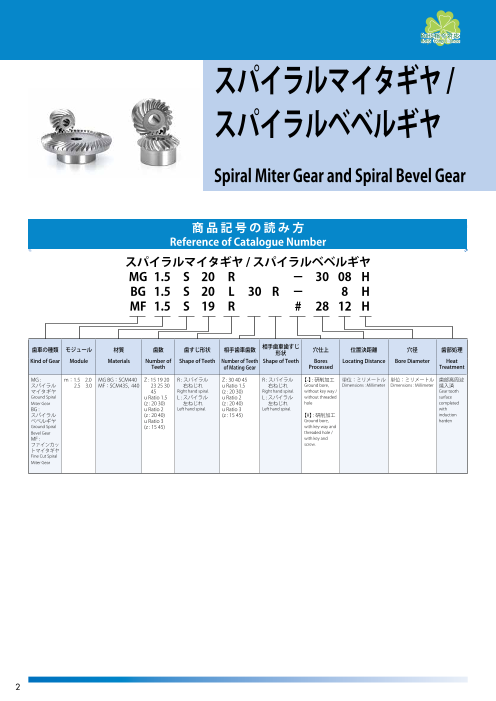
スパイラルマイタギヤ /
スパイラルベベルギヤ
Spiral Miter Gear and Spiral Bevel Gear
商 品 記 号 の 読 み 方
Reference of Catalogue Number
スパイラルマイタギヤ / スパイラルベベルギヤ
MG 1.5 S 20 R - 30 08 H
BG 1.5 S 20 L 30 R - 8 H
MF 1.5 S 19 R # 28 12 H
歯車の種類 モジュール 材質 歯数 歯すじ形状 相手歯車歯数 相手歯車歯すじ形状 穴仕上 位置決距離 穴径 歯部処理
Kind of Gear Module Materials Number of Shape of Teeth Number of Teeth Shape of Teeth Bores Locating Distance Bore Diameter Heat
Teeth of Mating Gear Processed Treatment
MG : m:1.5 2.0 MG BG:SCM440 Z : 15 19 20 R : スパイラル Z : 30 40 45 R : スパイラル 【-】 : 研削加工 単位:ミリメートル 単位:ミリメートル 歯部高周波
スパイラル 2.5 3.0 MF:SCM435, 440 23 25 30 右ねじれ u Ratio 1.5 右ねじれ Ground bore, Dimensions : Millimeter Dimensions : Millimeter 焼入済
マイタギヤ 45 Right hand spiral. (z : 20 30) Right hand spiral. without key way / Gear tooth
Ground Spiral u Ratio 1.5 L : スパイラル u Ratio 2 L : スパイラル without threaded surface
Miter Gear (z : 20 30) 左ねじれ (z : 20 40) 左ねじれ hole completed
BG : u Ratio 2 Left hand spiral. u Ratio 3 Left hand spiral. with
スパイラル (z : 20 40) (z : 15 45) 【#】 : 研削加工 induction
ベベルギヤ u Ratio 3 Ground bore, harden
Ground Spiral (z : 15 45) with key way and
Bevel Gear threaded hole /
MF : with key and
ファインカッ screw.
トマイタギヤ
Fine Cut Spiral
Miter Gear
2
Page3
KGギヤ・インフォメーション
KG Gear - Information
ファインカットベベルの特徴
Features of Fine Cut Spiral Miter Gears
コンパクトな設計とコストダウンに最適な高精度スパイラルマイタギヤです
Fine Cut Spiral Spiral Miter Gears are suitable for compact design and cost reductions
・JIS B 1704 2 級以上の精度に仕上げた高精度なスパイラルマイタギヤです
歯部を研磨せずに高精度に仕上げておりますので、同精度の歯研品と比較してコストダウンをご検討いただけます。
・P recision spiral miter gears with system of accuracy JIS B 1704 class 2 and above. This spiral miter gears offer competitive price compared with ground-finished JIS class2 spiral miter
gears.
・ コンパクト設計に最適な歯数 19 枚と 23 枚を採用しております。
ベアリングやオイルシールの規格を考慮して歯車を設計しました。
そのため、一般的な歯数 20 枚・25 枚のスパイラルマイタギヤと比較してベアリングサイズ等の歯車周辺の設計を含めサイズダウンが可能です。詳細は、以下を
ご参照ください。
・Number of teeth is 19 and 23 which is suitable for compact design
W e designed this spiral miter gears in consideration for standard sizes of bearings and oil seals. Therefore, you can make your design around gears like bearings smaller compared
with general spiral miter gears of number of teeth 20 and 25.
F or more details, please refer to the followings.
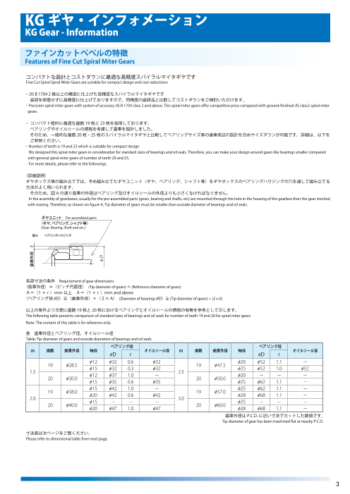
(詳細説明)
ギヤボックス等の組み立てでは、予め組み立てたギヤユニット(ギヤ、ベアリング、シャフト等)をギヤボックスのベアリングハウジングの穴を通して組み立てる
方法がよく用いられます。
そのため、図 A の通り歯車の外径はベアリング及びオイルシールの外径よりも小さくなければなりません。
In the assembly of gearboxes, usually for the pre-assembled parts (gears, bearing and shafts, etc) are mounted through the hole in the housing of the gearbox then the gear meshed
with mating. Therefore, as shown on figure A, Tip diameter of gears must be smaller than outside diameter of bearings and oil seals.
ギヤユニット Pre-assembled parts
(ギヤ、ベアリング、シャフト等)
(Gear, Bearing, Shaft and etc.)
図A ベアリングハウジング
r
各部寸法の条件 Requirement of gear dimensions
(歯車外径)≒(ピッチ円直径) (Tip diameter of gears) ≒ (Reference diameter of gears)
A=(1 +r)mm 以上 A=(1 +r)mm and above
(ベアリング径φD)≧(歯車外径)+(2× A) (Diameter of bearings φD)≧ (Tip diameter of gears) + (2 x A)
以上の条件より次表に歯数 19 枚と 20 枚におけるベアリングとオイルシールの規格の有無を参考として示します。
The following table presents comparison of standard sizes of bearings and oil seals for number of teeth 19 and 20 for spiral miter gears.
Note: The content of this table is for reference only.
表 歯車外径とベアリング径、オイルシール径
Table: Tip diameter of gears and outside diameters of bearings and oil seals
ベアリング径 ベアリング径
m 歯数 歯車外径 軸径 オイルシール径 m 歯数 歯車外径 軸径 オイルシール径
φD r φD r
φ12 φ32 0.6 φ32 φ20 φ52 1.1 -
19 φ28.5 19 φ47.5
φ15 φ32 0.3 φ32 φ25 φ52 1.0 φ52
1.5 2.5
φ12 φ37 1.0 - φ20 - - -
20 φ30.0 20 φ50.0
φ15 φ35 0.6 φ35 φ25 φ62 1.1 -
φ15 φ42 1.0 - φ25 φ62 1.1 -
19 φ38.0 19 φ57.0
φ20 φ42 0.6 φ42 φ28 φ68 1.1 -
2.0 3.0
φ15 - - - φ25 - - -
20 φ40.0 20 φ60.0
φ20 φ47 1.0 φ47 φ28 φ68 1.1 -
歯車外径は P.C.D. に近い寸法でカットした数値です。
Tip diameter of gear has been machined flat at nearby P.C.D.
寸法表は次ページをご覧ください。
Please refer to dimensional table from next page.
3
歯車外径 A
φ D
Page4
KGギヤ・インフォメーション
KG Gear - Information
KG 歯研スパイラルベベルギヤの特徴
Feature of GROUND SPIRAL BEVEL GEARS
JIS B 1704 1 級以上の精度に仕上げた高精度スパイラルベベルギヤです。
High precision spiral bevel gears with system of accuracy JIS B 1704 class 1 and above.
・高精度な歯車仕様
歯車精度は、歯面研削仕上げの JIS B 1704 1 級以上となります。
モジュールサイズは m = 1.5、2.0、2.5、3.0 よりお選びいただけます。
歯数比は、u=1:1、1:1.5、1:2、1:3(m=3.0 は、u=1:1 のみ)よりお選びいただけます。
バックラッシ量は 30 μ以下の設定が可能です。
・High precision Spiral Miter and Bevel Gears
Size of module is available from 1.5 to 3.0.
Available ratio are u=1:1, 1.5:1, 2:1 and 3:1 (Gears of module 3.0 is u=1:1 only).
Amount of backlash can be set 30μmm and below
・高速運転に最適
歯切品と比較して高速回転が可能で静粛性にも富んでおります。
・Suitable for high speed operation
Suitable for high revolution, less oscillation and low noise usage compared with cutting finished products.
・高強度仕様
歯部高周波焼入れ後、歯部に研磨加工を施し、高精度に仕上げております。そのため、歯切品と比較して曲げ強度、歯面強さが 20%以上向上しております。
・High strength gears
After hardening of the tooth part, the tooth part is ground and finished with high precision. Therefore, the bending strength and the tooth surface durability are improved by 20%
or more compared with cutting-finished products.
・高精度にカスタマイズ
お客様での追加工時の精度維持と加工性を重視し、ハブ外周及び歯先外周は研磨加工仕上げを施しております(歯先外周は、軸心と平行に面取りをしてあります
ので、精度良くチャッキング出来ます)。追加工時の注意事項は、図 A 及び、KG 総合カタログの「KG STOCKG GEARS の追加工上の注意」をご参照ください。
・For precise modification
・W e place importance on maintaining accuracy at the time of additional work by the customer and process-ability, and the Hub diameter and the Tip diameter are ground. Please
refer to page-16 for notes on additional processing
(注記事項)
歯切品や他の製品との噛み合いは避け、当社製・歯研品同士でのご使用として下さい
運転時は回転数や負荷から適正な油かグリース潤滑にてご使用ください
Note:
Please avoid meshing with other product’ s series, or use with other company’ s products.
For lubrication of the gears, please use appropriate oil or grease base on the rpm and torque.
図 B 高精度にカスタマイズ
※必ず生づめスクロールチャックを用いて、商品の穴面の振れを極力 0 に近付けてください(目標 0.003mm 以内)。
Figure B
We recommend the use of three-jaw chuck (scroll chuck) that is not surface hardened for centering of the gear. In order to maintain the quality of performance after the additional
machining, the run-out tolerance of the gear to the chuck should be 0-0.003mm.
G
G
G
高精度に追加工をして頂くためにハブ外周及 高精度に追加工をして頂くために歯先外周及
び、端面を研磨仕上げしています。 び、端面を研磨仕上げしています。
The drawing above is highly recommended to The drawing above is highly recommended to
follow, in order to obtain the centering easier follow, in order to obtain the centering easier
because the gear has been ground because the gear has been ground
4
G
G
G
G
G
G
G
Page5
歯研スパイラルマイタギヤ モジュール 1.5/2 圧力角 20° 歯数比 1 : 1 ねじれ角 35°GROUND SPIRAL MITER GEARS MODULE 1 : 1 Ratio 20°PRESSURE ANGLE 35°SPIRAL ANGLE
歯部高周波焼入れ HRC 52 ~ 58
Gear tooth surface completed with induction hardening, Hardness HRC 52 ~ 58
JIS B 1704 1 級
System of Accuracy : JIS B 1704 class1 RoHS指令対応
RoHS Compliance A
lw
lh
b
G
ds l G dd dh d da
la
SCM440 クロムモリブデン鋼 (JIS G4053) 単位:mm
Material : Chromium Molybdenum Steel (ISO 42CrMo4) Dimensions:mm
歯数比 歯 数 基準円 歯先円 組 立 穴 径 ハ ブ ハ ブ 穴長さ 全 長 歯 幅 キ ー ね じ 歯先角 重 量
直 径 直 径 距 離 外 径 長 さ み ぞ
商 品 記 号 Ratio Number Reference Tip Locating Bore Hub Hub Bore Overall Tip Face Key Set Screw Face Weight
Catalogue Number of Teeth Diameter Diameter Distance Diameter Diameter Projection Length Length Distance Width Way Angle
u z d da A dd(H7) dh lh l lw la b b2 × t2 M ls δa ds W(g)
MG1.5S 20R-3008H φ1 20 φ30 ( 31.92)φ30.5 30 φ8 φ26 13 19 21.11 15.96 8 - - - 50°08’ φ15.37 74.4
MG1.5S 20L-3008H φ1 20 φ30 ( 31.92)φ30.5 30 φ8 φ26 13 19 21.11 15.96 8 - - - 50°08’ φ15.37 74.4
MG1.5S 25R-3410H φ1 25 φ37.5 ( 39.43)φ38 34 φ10 φ32 12.5 19 22.1 16.21 9 - - - 49°18’ φ19.54 118.2
MG1.5S 25L-3410H φ1 25 φ37.5 ( 39.43)φ38 34 φ10 φ32 12.5 19 22.1 16.21 9 - - - 49°18’ φ19.54 118.2
MG1.5S 30R-4310H φ1 30 φ45 ( 46.81)φ45.2 43 φ10 φ40 18 25 28.13 21.41 10 - - - 47°48’ φ25.72 240.6
MG1.5S 30L-4310H 1 30 φ45 (φ46.81)φ45.2 43 φ10 φ40 18 25 28.13 21.41 10 - - - 47°48’ φ25.72 240.6
MG2S 20R-3712H φ1 20 φ40 ( 42.53)φ41 37 φ12 φ35 14.5 22 24.71 18.27 10 - - - 50°04’ φ21.72 152.3
MG2S 20L-3712H φ1 20 φ40 ( 42.53)φ41 37 φ12 φ35 14.5 22 24.71 18.27 10 - - - 50°04’ φ21.72 152.3
MG2S 25R-4012H φ1 25 φ50 ( 52.58)φ51 40 φ12 φ44 12 20 24.12 16.29 12 - - - 49°25’ φ26.06 238.4
MG2S 25L-4012H φ1 25 φ50 ( 52.58)φ51 40 φ12 φ44 12 20 24.12 16.29 12 - - - 49°25’ φ26.06 238.4
MG2S 30R-5012H φ1 30 φ60 ( 62.41)φ60.8 50 φ12 φ52 16 25 29.12 21.21 12 - - - 47°52’ φ36.06 427.8
MG2S 30L-5012H φ1 30 φ60 ( 62.41)φ60.8 50 φ12 φ52 16 25 29.12 21.21 12 - - - 47°52’ φ36.06 427.8
歯先円直径 da の( )内は理論値です。最大外径は軸心と平行に面取りしてありますので、理論値よ
り小さくなっています。
The numeric indicated in the bracket ( ) under the column. Outside diameter da has been machined flat. With this
process, the outer diameter is smaller than the theory with respect to shaft center to parallel.
許容伝達動力表 曲げ強さ (kW) 許容伝達動力表 歯面強さ(kW)
Allowable transfer capability table (kW) Bending Strength Allowable transfer capability table (kW) Surface Durability
回転速度(min-1) 回転速度(min-1)
商 品 記 号 revolution/min revolution/min
Catalogue Numbers
250 500 800 1,000 1,500 2,000 2,500 3,000 4,000 250 500 800 1,000 1,500 2,000 2,500 3,000 4,000
MG1.5S 20R-3008H 0.15 0.31 0.48 0.59 0.86 1.11 1.36 1.61 2.09 0.08 0.17 0.27 0.33 0.49 0.64 0.79 0.94 1.24
MG1.5S 25R-3410H 0.23 0.47 0.72 0.89 1.27 1.66 2.03 2.40 3.11 0.15 0.32 0.50 0.62 0.91 1.20 1.48 1.76 2.32
MG1.5S 30R-4310H 0.33 0.65 1.01 1.23 1.77 2.30 2.83 3.33 4.26 0.26 0.53 0.84 1.04 1.52 2.00 2.48 2.95 3.82
MG2S 20R-3712H 0.35 0.69 1.07 1.31 1.88 2.45 3.00 3.55 4.58 0.19 0.39 0.61 0.76 1.11 1.46 1.80 2.15 2.81
MG2S 25R-4012H 0.55 1.08 1.66 2.03 2.93 3.80 4.66 5.49 6.95 0.37 0.76 1.19 1.47 2.16 2.84 3.51 4.17 5.35
MG2S 30R-5012H 0.72 1.41 2.16 2.63 3.80 4.95 6.05 7.04 8.79 0.59 1.19 1.86 2.29 3.37 4.44 5.49 6.43 8.13
The above references are JGMA standard.
5
G
G
Page6
歯研スパイラルマイタギヤ モジュール 圧力角 20° 歯数比 1 : 1 ねじれ角 35°
GROUND SPIRAL MITER GEARS MODULE 2.5/3 1 : 1 Ratio 20°PRESSURE ANGLE 35°SPIRAL ANGLE
歯部高周波焼入れ HRC 52 ~ 58 ds の寸法は参考値です。
Gear tooth surface completed with induction hardening, Hardness HRC 52 ~ 58 Dimension of ds is for reference only.
JIS B 1704 1 級
System of Accuracy : JIS B 1704 class1 RoHS指令対応
RoHS Compliance A
lw
lh
b
G
ds l G dd dh d da
la
SCM440 クロムモリブデン鋼 (JIS G4053) 単位:mm
Material : Chromium Molybdenum Steel (ISO 42CrMo4) Dimensions:mm
歯数比 歯 数 基準円 歯先円 組 立 穴 径 ハ ブ ハ ブ 穴長さ 全 長 歯 幅 キ ー ね じ 歯先角 重 量
直 径 直 径 距 離 外 径 長 さ み ぞ
商 品 記 号 Ratio Number Reference Tip Locating Bore Hub Hub Bore Overall Tip Face Key Set Screw Face Weight
Catalogue Number of Teeth Diameter Diameter Distance Diameter Diameter Projection Length Length Distance Width Way Angle
u z d da A dd(H7) dh lh l lw la b b2 × t2 M ls δa ds W(g)
MG2.5S 20R-4814H φ1 20 φ50 ( 53.22)φ51.5 48 φ14 φ44 20 29 32.28 24.61 12 - - - 50°32’ φ28.06 321.2
MG2.5S 20L-4814H φ1 20 φ50 ( 53.22)φ51.5 48 φ14 φ44 20 29 32.28 24.61 12 - - - 50°32’ φ28.06 321.2
MG2.5S 25R-5016H φ1 25 φ62.5 ( 65.61)φ64 50 φ16 φ54 14.5 26 30.21 20.31 15 - - - 48°49’ φ34.57 456.8
MG2.5S 25L-5016H φ1 25 φ62.5 ( 65.61)φ64 50 φ16 φ54 14.5 26 30.21 20.31 15 - - - 48°49’ φ34.57 456.8
MG2.5S 30R-6216H 1 30 φ75 (φ78.03)φ76.5 62 φ16 φ66 20 32 36.08 26.01 15 - - - 47°56’ φ47.57 848.3
MG2.5S 30L-6216H φ1 30 φ75 ( 78.03)φ76.5 62 φ16 φ66 20 32 36.08 26.01 15 - - - 47°56’ φ47.57 848.3
MG3S 20R-5816H φ1 20 φ60 ( 63.8)φ62 58 φ16 φ52 24 35 39.57 29.9 15 - - - 50°04’ φ31.57 556.1
MG3S 20L-5816H φ1 20 φ60 ( 63.8)φ62 58 φ16 φ52 24 35 39.57 29.9 15 - - - 50°04’ φ31.57 556.1
歯先円直径 da の( )内は理論値です。最大外径は軸心と平行に面取りしてありますので、理論値よ
り小さくなっています。
The numeric indicated in the bracket ( ) under the column. Outside diameter da has been machined flat. With this
process, the outer diameter is smaller than the theory with respect to shaft center to parallel.
許容伝達動力表 曲げ強さ (kW) 許容伝達動力表 歯面強さ(kW)
Allowable transfer capability table (kW) Bending Strength Allowable transfer capability table (kW) Surface Durability
回転速度(min-1) 回転速度(min-1)
商 品 記 号 revolution/min revolution/min
Catalogue Numbers
250 500 800 1,000 1,500 2,000 2,500 3,000 4,000 250 500 800 1,000 1,500 2,000 2,500 3,000 4,000
MG2.5S 20R-4814H 0.66 1.29 1.99 2.43 3.50 4.55 5.58 6.57 8.32 0.37 0.74 1.17 1.44 2.12 2.78 3.44 4.09 5.24
MG2.5S 25R-5016H 1.07 2.07 3.16 3.86 5.58 7.26 8.86 10.28 - 0.74 1.49 2.32 2.86 4.21 5.55 6.83 7.99 -
MG2.5S 30R-6216H 1.41 2.69 4.09 5.02 7.27 9.43 11.33 13.08 - 1.18 2.33 3.61 4.48 6.59 8.66 10.51 12.23 -
MG3S 20R-5816H 1.16 2.25 3.44 4.19 6.07 7.90 9.66 11.23 14.03 0.66 1.32 2.06 2.53 3.74 4.92 6.08 7.13 9.01
The above references are JGMA standard.
6
G
G
Page7
歯研スパイラルベベルギヤ モジュール 圧力角 20° 歯数比 1:1.5, 1:2, 1:3 ねじれ角 35°
GROUND SPIRAL BEVEL GEARS MODULE 1.5/2 1:1.5, 1:2 and 1:3 Ratio 20° PRESSURE ANGLE 35° SPIRAL ANGLE
歯部高周波焼入れ HRC 52 ~ 58
Gear tooth surface completed with induction hardening, Hardness HRC 52 ~ 58
JIS B 1704 1 級
System of Accuracy : JIS B 1704 class1 RoHS指令対応
RoHS Compliance
A
lw
lh
b
G
ds l G dd dh d da
la
SCM440 クロムモリブデン鋼 (JIS G4053) 単位:mm
Material : Chromium Molybdenum Steel (ISO 42CrMo4) Dimensions:mm
歯数比 歯 数 基準円 歯先円 組 立 穴 径 ハ ブ ハ ブ 穴長さ 全 長 歯 幅 キ ー ね じ 歯先角 重 量
直 径 直 径 距 離 外 径 長 さ み ぞ
商 品 記 号 Ratio Number Reference Tip Locating Bore Hub Hub Bore Overall Tip Face Key Set Screw Face Weight
Catalogue Number of Teeth Diameter Diameter Distance Diameter Diameter Projection Length Length Distance Width Way Angle
u z d da A dd(H7) dh lh l lw la b b2 × t2 M ls δa ds W(g)
BG1.5S 20L30R-8H φ1.5 20 φ30 ( 32.96)φ31.5 37 φ8 φ26 13.16 20 22.49 15.48 9 - - - 39°08’ φ14.07 79.0
BG1.5S 30R20L-8H φ1.5 30 φ45 ( 46.02)φ44.6 26 φ8 φ32 8 14 16.39 11.77 9 - - - 59°11’ φ27.45 112.8
BG1.5S 20L40R-8H φ2 20 φ30 ( 33.45)φ32 45 φ8 φ26 14 24 25.29 15.87 11 - - - 31°21’ φ16.80 90.5
BG1.5S 40R20L-10H φ2 40 φ60 ( 60.69)φ59.5 30 φ10 φ40 10 18 20.27 15.69 11 - - - 65°24’ φ38.40 247.9
BG1.5S 15L45R-8H (φ3 15 φ22.5 26.37)φ25.2 45 φ8 φ20 10.83 21 22.03 11.89 11 - - - 23°19’ φ11.45 42.3
BG1.5S 45R15L-12H φ3 45 φ67.5 ( 67.92)φ67 30 φ12 φ45 12 20 22.56 19.38 11 - - - 73°13’ φ45.14 350.3
BG2S 20L30R-10H φ1.5 20 φ40 ( 43.94)φ42.2 45 φ10 φ34 12.99 22 24.87 16.31 11 - - - 39°12’ φ21.36 153.4
BG2S 30R20L-12H φ1.5 30 φ60 ( 61.35)φ60 40 φ12 φ40 15 23 26.66 21.02 11 - - - 59°12’ φ37.55 294.8
BG2S 20L40R-12H 2 20 φ40 (φ44.68)φ43.2 60 φ12 φ35 18.75 32 34 21.17 15 - - - 31°36’ φ20.91 175.8
BG2S 40R20L-12H φ2 40 φ80 ( 80.93)φ79.5 45 φ12 φ50 18 27 32.16 25.93 15 - - - 65°29’ φ48.46 616.2
BG2S 15L45R-10H (φ3 15 φ30 35.13)φ33.8 60 φ10 φ24.5 14.08 29 29.69 15.85 15 - - - 23°07’ φ19.16 94.4
BG2S 45R15L-12H φ3 45 φ90 ( 90.55)φ89.5 40 φ12 φ60 17 26 30.18 25.83 15 - - - 73°07’ φ59.04 815.4
歯先円直径 da の( )内は理論値です。最大外径は軸心と平行に面取りしてありますので、理論値よ
り小さくなっています。
The numeric indicated in the bracket ( ) under the column. Outside diameter da has been machined flat. With this
process, the outer diameter is smaller than the theory with respect to shaft center to parallel.
許容伝達動力表 曲げ強さ (kW) 許容伝達動力表 歯面強さ(kW)
Allowable transfer capability table (kW) Bending Strength Allowable transfer capability table (kW) Surface Durability
回転速度(min-1) 回転速度(min-1)
商 品 記 号 revolution/min revolution/min
Catalogue Numbers
250 500 800 1,000 1,500 2,000 2,500 3,000 4,000 250 500 800 1,000 1,500 2,000 2,500 3,000 4,000
BG1.5S 20L30R-8H 0.19 0.37 0.59 0.72 1.04 1.34 1.65 1.95 2.53 0.11 0.23 0.37 0.46 0.68 0.89 1.10 1.31 1.73
BG1.5S 20L40R-8H 0.24 0.47 0.75 0.92 1.33 1.72 2.11 2.49 3.24 0.15 0.30 0.49 0.61 0.89 1.17 1.45 1.72 2.26
BG1.5S 15L45R-8H 0.18 0.36 0.58 0.71 1.04 1.35 1.64 1.94 2.52 0.08 0.17 0.28 0.35 0.53 0.69 0.85 1.01 1.33
BG2S 20L30R-10H 0.41 0.83 1.28 1.57 2.25 2.94 3.59 4.25 5.48 0.26 0.53 0.84 1.04 1.52 2.00 2.48 2.95 3.86
BG2S 20L40R-12H 0.56 1.13 1.75 2.14 3.07 4.00 4.89 5.78 7.47 0.36 0.74 1.18 1.46 2.13 2.81 3.47 4.13 5.41
BG2S 15L45R-10H 0.42 0.85 1.34 1.65 2.39 3.08 3.78 4.46 5.80 0.21 0.43 0.69 0.86 1.26 1.65 2.04 2.43 3.20
The above references are JGMA standard.
7
G
G
Page8
歯研スパイラルベベルギヤ モジュール 2.5 圧力角 20° 歯数比 1:1.5, 1:2, 1:3 ねじれ角 35°GROUND SPIRAL BEVEL GEARS MODULE 1:1.5, 1:2 and 1:3 Ratio 20° PRESSURE ANGLE 35° SPIRAL ANGLE
歯部高周波焼入れ HRC 52 ~ 58 ds の寸法は参考値です。
Gear tooth surface completed with induction hardening, Hardness HRC 52 ~ 58 Dimension of ds is for reference only.
JIS B 1704 1 級
System of Accuracy : JIS B 1704 class1 RoHS指令対応
RoHS Compliance
A
lw
lh
b
G
ds l G dd dh d da
la
SCM440 クロムモリブデン鋼 (JIS G4053) 単位:mm
Material : Chromium Molybdenum Steel (ISO 42CrMo4) Dimensions:mm
歯数比 歯 数 基準円 歯先円 組 立 穴 径 ハ ブ ハ ブ 穴長さ 全 長 歯 幅 キ ー ね じ 歯先角 重 量
直 径 直 径 距 離 外 径 長 さ み ぞ
商 品 記 号 Ratio Number Reference Tip Locating Bore Hub Hub Bore Overall Tip Face Key Set Screw Face Weight
Catalogue Number of Teeth Diameter Diameter Distance Diameter Diameter Projection Length Length Distance Width Way Angle
u z d da A dd(H7) dh lh l lw la b b2 × t2 M ls δa ds W(g)
BG2.5S 20L30R-12H φ1.5 20 φ50 ( 55)φ53.5 55 φ12 φ44 15.49 28 30.81 19.16 15 - - - 39°24’ φ27.44 311.0
BG2.5S 30R20L-15H φ1.5 30 φ75 ( 76.72)φ75 50 φ15 φ50 18 30 33.97 26.3 15 - - - 59°17’ φ45.6 605.3
BG2.5S 20L40R-12H (φ2 20 φ50 55.55)φ54.2 75 φ12 φ44 23.5 40 43.66 26.39 20 - - - 30°31’ φ20.54 441.2
BG2.5S 40R20L-15H (φ2 40 φ100 101.1)φ100 55 φ15 φ65 20 34 39.55 31.1 20 - - - 65°01’ φ59.28 1294.1
BG2.5S 15L45R-12H φ3 15 φ37.5 ( 43.55)φ42.5 75 φ12 φ33 18 37 38.34 19.75 20 - - - 21°57’ φ20.54 206.6
BG2.5S 45R15L-15H φ3 45 φ112.5 ( 113.15)φ112.2 50 φ15 φ75 22 35 38.16 32.22 20 - - - 72°43’ φ72.84 1655.6
歯先円直径 da の( )内は理論値です。最大外径は軸心と平行に面取りしてありますので、理論値よ
り小さくなっています。
The numeric indicated in the bracket ( ) under the column. Outside diameter da has been machined flat. With this
process, the outer diameter is smaller than the theory with respect to shaft center to parallel.
許容伝達動力表 曲げ強さ (kW) 許容伝達動力表 歯面強さ(kW)
Allowable transfer capability table (kW) Bending Strength Allowable transfer capability table (kW) Surface Durability
回転速度(min-1) 回転速度(min-1)
商 品 記 号 revolution/min revolution/min
Catalogue Numbers
250 500 800 1,000 1,500 2,000 2,500 3,000 4,000 250 500 800 1,000 1,500 2,000 2,500 3,000 4,000
BG2.5S 20L30R-12H 0.85 1.68 2.59 3.16 4.56 5.91 7.26 8.55 10.82 0.54 1.10 1.73 2.13 3.14 4.12 5.11 6.06 7.77
BG2.5S 20L40R-12H 1.14 2.24 3.45 4.21 6.08 7.89 9.68 11.40 14.43 0.75 1.52 2.39 2.94 4.32 5.68 7.04 8.36 10.71
BG2.5S 15L45R-12H 0.85 1.71 2.66 3.26 4.67 6.08 7.44 8.80 11.41 0.43 0.89 1.41 1.74 2.54 3.35 4.14 4.93 6.48
The above references are JGMA standard.
8
G
G
Page9
ファインカットマイタギヤ モジュール 圧力角 20° 歯数比 1 : 1 ねじれ角 35°
FINE CUT SPIRAL MITER GEARS MODULE 1.5 1 : 1 Ratio 20°PRESSURE ANGLE 35°SPIRAL ANGLE
歯部高周波焼入 HRC47 ~ 51
JIS B1704 2 級 New 仕様変更 締結加工不要。
System of accuracy : JIS B1704 Class 2 Additional machining on tightening is not necessary.
RoHS指令対応
RoHS Compliance A
lw
lh
b
l 2-M (120°)G s
b2
120°
t2
ds l G dd dh d da
la
SCM435、440 クロムモリブデン鋼(JIS G 4053) 単位:mm
Material : Chromium Molybdenum Steel (ISO 34CrMo4,42CrMo4) Dimensions:mm
歯 数 基準円 歯先円 組 立 穴 径 ハ ブ ハ ブ 穴長さ 全 長 歯 幅 キ ー ね じ 歯先角 重 量
直 径 直 径 距 離 外 径 長 さ み ぞ
商 品 記 号 Number Reference Tip Locating Bore Hub Hub Bore Overall Tip Face Key Set Screw Face Weight
Catalogue Number of Teeth Diameter Diameter Distance Diameter Diameter Projection Length Length Distance Width Way Angle
z d da A dd(H7) dh lh l lw la b b2 × t2 M ls δa ds W(g)
MF1.5S 19R - 2810H φ19 φ28.5 ( 30.34)φ28.5 28 φ10 φ25 12 16 18.19 14.67 5.5 - - - 50°23’ φ17.4 54.7
MF1.5S 19L - 2810H φ19 φ28.5 ( 30.34)φ28.5 28 φ10 φ25 12 16 18.19 14.67 5.5 - - - 50°23’ φ17.4 54.7
MF1.5S 19R # 2812H (φ19 φ28.5 30.34)φ28.5 28 φ12 φ25 12 16 18.19 14.67 5.5 4 × 1.8 2-M4 6 50°23’ φ17.4 49.1
MF1.5S 19L # 2812H φ19 φ28.5 ( 30.34)φ28.5 28 φ12 φ25 12 16 18.19 14.67 5.5 4 × 1.8 2-M4 6 50°23’ φ17.4 49.1
MF1.5S 23R - 3212H (φ23 φ34.5 36.33)φ34.5 32 φ12 φ30 12.5 18 19.91 15.67 6.5 - - - 49°22’ φ22.6 88.1
MF1.5S 23L - 3212H (φ23 φ34.5 36.33)φ34.5 32 φ12 φ30 12.5 18 19.91 15.67 6.5 - - - 49°22’ φ22.6 88.1
MF1.5S 23R # 3215H φ23 φ34.5 ( 36.33)φ34.5 32 φ15 φ30 12.5 18 19.91 15.67 6.5 5 × 2.3 2-M5 8 49°22’ φ22.6 77.1
MF1.5S 23L # 3215H (φ23 φ34.5 36.33)φ34.5 32 φ15 φ30 12.5 18 19.91 15.67 6.5 5 × 2.3 2-M5 8 49°22’ φ22.6 77.1
カタログ記号の末尾に【H】を付した商品は歯部高周波焼入済です。[H] : Gear tooth surface completed with induction hardening, Hardness HRC 47 to 51.
【#】(シャープ)にはキー材とセットスクリューが付いております。[#] : Gear with key way and threaded hole / with key and screw.
歯先円直径 da の( )内は理論値です。最大外径は軸心と平行に面取りしてありますので、理論値よ
り小さくなっています。
The numeric indicated in the bracket ( ) under the column. Outside diameter da has been machined flat. With this
process, the outer diameter is smaller than the theory with respect to shaft center to parallel.
許容伝達動力表 曲げ強さ (kW) 歯面強さ(kW)
Allowable transfer capability table (kW) Bending Strength Allowable transfer capability table (kW) Surface Durability
回転速度(min-1) 回転速度(min-1)
商 品 記 号 revolution/min revolution/min
Catalogue Numbers
100 250 500 800 1,000 1,500 2,000 100 250 500 800 1,000 1,500 2,000
MF1.5S 19R 0.054 0.137 0.274 0.432 0.525 0.736 0.922 0.025 0.067 0.138 0.223 0.273 0.391 0.495
MF1.5S 23R 0.084 0.212 0.424 0.652 0.789 1.094 1.385 0.047 0.123 0.255 0.401 0.489 0.691 0.886
The above references are JGMA standard.
9
Page10
ファインカットマイタギヤ モジュール 圧力角 20° 歯数比 1 : 1 ねじれ角 35°
FINE CUT SPIRAL MITER GEARS MODULE 2 1 : 1 Ratio 20°PRESSURE ANGLE 35°SPIRAL ANGLE
歯部高周波焼入 HRC47 ~ 51 御注文には必ず “フルネームで商品記号” を明記してください。
JIS B1704 2 級
System of accuracy : JIS B1704 Class 2 Please refer to the catalogue reference while ordering.
RoHS指令対応 ds の寸法は参考値です。
RoHS Compliance A Dimension of ds is for reference only.
lw
lh
b
l 2-M (120°)G s
b2
120°
t2
ds l G dd dh d da
la
SCM435、440 クロムモリブデン鋼(JIS G 4053) 単位:mm
Material : Chromium Molybdenum Steel (ISO 34CrMo4,42CrMo4) Dimensions:mm
歯 数 基準円 歯先円 組 立 穴 径 ハ ブ ハ ブ 穴長さ 全 長 歯 幅 キ ー ね じ 歯先角 重 量
直 径 直 径 距 離 外 径 長 さ み ぞ
商 品 記 号 Number Reference Tip Locating Bore Hub Hub Bore Overall Tip Face Key Set Screw Face Weight
Catalogue Number of Teeth Diameter Diameter Distance Diameter Diameter Projection Length Length Distance Width Way Angle
z d da A dd(H7) dh lh l lw la b b2 × t2 M ls δa ds W(g)
MF2S 19R - 3512H φ19 φ38 ( 40.43)φ38.0 35 φ12 φ32 13 19 22.09 17.21 7.5 - - - 49°39’ φ22.8 113.4
MF2S 19L - 3512H φ19 φ38 ( 40.43)φ38.0 35 φ12 φ32 13 19 22.09 17.21 7.5 - - - 49°39’ φ22.8 113.4
MF2S 19R # 3515H 19 φ38 (φ40.43)φ38.0 35 φ15 φ32 13 19 22.09 17.21 7.5 5 × 2.3 2-M5 8 49°39’ φ22.8 101.9
MF2S 19L # 3515H φ19 φ38 ( 40.43)φ38.0 35 φ15 φ32 13 19 22.09 17.21 7.5 5 × 2.3 2-M5 8 49°39’ φ22.8 101.9
MF2S 23R - 4015H (φ23 φ46 48.52)φ46.0 40 φ15 φ40 14 21 24.43 18.26 9.5 - - - 49°39’ φ27.1 191.9
MF2S 23L - 4015H (φ23 φ46 48.52)φ46.0 40 φ15 φ40 14 21 24.43 18.26 9.5 - - - 49°39’ φ27.1 191.9
MF2S 23R # 4020H φ23 φ46 ( 48.52)φ46.0 40 φ20 φ40 14 21 24.43 18.26 9.5 6 × 2.8 2-M5 9 49°39’ φ27.1 166.5
MF2S 23L # 4020H (φ23 φ46 48.52)φ46.0 40 φ20 φ40 14 21 24.43 18.26 9.5 6 × 2.8 2-M5 9 49°39’ φ27.1 166.5
カタログ記号の末尾に【H】を付した商品は歯部高周波焼入済です。[H] : Gear tooth surface completed with induction hardening, Hardness HRC 47 to 51.
【#】(シャープ)にはキー材とセットスクリューが付いております。[#] : Gear with key way and threaded hole / with key and screw.
歯先円直径 da の( )内は理論値です。最大外径は軸心と平行に面取りしてありますので、理論値よ
り小さくなっています。
The numeric indicated in the bracket ( ) under the column. Outside diameter da has been machined flat. With this
process, the outer diameter is smaller than the theory with respect to shaft center to parallel.
許容伝達動力表 曲げ強さ (kW) 歯面強さ(kW)
Allowable transfer capability table (kW) Bending Strength Allowable transfer capability table (kW) Surface Durability
回転速度(min-1) 回転速度(min-1)
商 品 記 号 revolution/min revolution/min
Catalogue Numbers
100 250 500 800 1,000 1,500 2,000 100 250 500 800 1,000 1,500 2,000
MF2S 19R 0.133 0.334 0.668 1.014 1.223 1.685 2.150 0.064 0.167 0.344 0.533 0.649 0.911 1.178
MF2S 23R 0.215 0.539 1.060 1.587 1.901 2.640 3.359 0.123 0.320 0.648 0.991 1.199 1.694 2.183
The above references are JGMA standard.
10
Page11
ファインカットマイタギヤ モジュール 圧力角 20° 歯数比 1 : 1 ねじれ角 35°
FINE CUT SPIRAL MITER GEARS MODULE 2.5 1 : 1 Ratio 20°PRESSURE ANGLE 35°SPIRAL ANGLE
歯部高周波焼入 HRC47 ~ 51
JIS B1704 2 級 New 仕様変更 締結加工不要。
System of accuracy : JIS B1704 Class 2 Additional machining on tightening is not necessary.
RoHS指令対応
RoHS Compliance A
lw
lh
b
l 2-M (120°)G s
b2
120°
t2
ds l G dd dh d da
la
SCM435、440 クロムモリブデン鋼(JIS G 4053) 単位:mm
Material : Chromium Molybdenum Steel (ISO 34CrMo4,42CrMo4) Dimensions:mm
歯 数 基準円 歯先円 組 立 穴 径 ハ ブ ハ ブ 穴長さ 全 長 歯 幅 キ ー ね じ 歯先角 重 量
直 径 直 径 距 離 外 径 長 さ み ぞ
商 品 記 号 Number Reference Tip Locating Bore Hub Hub Bore Overall Tip Face Key Set Screw Face Weight
Catalogue Number of Teeth Diameter Diameter Distance Diameter Diameter Projection Length Length Distance Width Way Angle
z d da A dd(H7) dh lh l lw la b b2 × t2 M ls δa ds W(g)
MF2.5S 19R - 4215H φ19 φ47.5 ( 50.55)φ47.5 42 φ15 φ40 14.5 23 25.93 19.78 9.5 - - - 49°48’ φ30.1 210.8
MF2.5S 19L - 4215H φ19 φ47.5 ( 50.55)φ47.5 42 φ15 φ40 14.5 23 25.93 19.78 9.5 - - - 49°48’ φ30.1 210.8
MF2.5S 19R # 4220H (φ19 φ47.5 50.55)φ47.5 42 φ20 φ40 14.5 23 25.93 19.78 9.5 6 × 2.8 2-M6 10 49°48’ φ30.1 182.5
MF2.5S 19L # 4220H φ19 φ47.5 ( 50.55)φ47.5 42 φ20 φ40 14.5 23 25.93 19.78 9.5 6 × 2.8 2-M6 10 49°48’ φ30.1 182.5
MF2.5S 23R - 4815H φ23 φ57.5 ( 60.63)φ57.5 48 φ15 φ50 15.5 24 28.30 20.81 11.5 - - - 49°30’ φ34.5 363.9
MF2.5S 23L - 4815H φ23 φ57.5 ( 60.63)φ57.5 48 φ15 φ50 15.5 24 28.30 20.81 11.5 - - - 49°30’ φ34.5 363.9
MF2.5S 23R # 4825H φ23 φ57.5 ( 60.63)φ57.5 48 φ25 φ50 15.5 24 28.30 20.81 11.5 8 × 3.3 2-M6 10 49°30’ φ34.5 300.5
MF2.5S 23L # 4825H (φ23 φ57.5 60.63)φ57.5 48 φ25 φ50 15.5 24 28.30 20.81 11.5 8 × 3.3 2-M6 10 49°30’ φ34.5 300.5
カタログ記号の末尾に【H】を付した商品は歯部高周波焼入済です。[H] : Gear tooth surface completed with induction hardening, Hardness HRC 47 to 51.
【#】(シャープ)にはキー材とセットスクリューが付いております。[#] : Gear with key way and threaded hole / with key and screw.
歯先円直径 da の( )内は理論値です。最大外径は軸心と平行に面取りしてありますので、理論値よ
り小さくなっています。
The numeric indicated in the bracket ( ) under the column. Outside diameter da has been machined flat. With this
process, the outer diameter is smaller than the theory with respect to shaft center to parallel.
許容伝達動力表(kW)曲げ強さ 許容伝達動力表(kW)歯面強さ
Allowable transfer capability table (kW) Bending Strength Allowable transfer capability table (kW) Surface Durability
回転速度(min-1) 回転速度(min-1)
商 品 記 号 revolution/min revolution/min
Catalogue Numbers
100 250 500 800 1,000 1,500 2,000 100 250 500 800 1,000 1,500 2,000
MF2.5S 19R 0.264 0.662 1.298 1.939 2.321 3.228 4.103 0.128 0.335 0.678 1.034 1.250 1.769 2.278
MF2.5S 23R 0.414 1.036 1.980 2.923 3.474 4.897 6.240 0.240 0.624 1.230 1.853 2.224 3.192 4.119
The above references are JGMA standard.
11
Page12
ファインカットマイタギヤ モジュール 3 圧力角 20° 歯数比 1 : 1 ねじれ角 35°FINE CUT SPIRAL MITER GEARS MODULE 1 : 1 Ratio 20°PRESSURE ANGLE 35°SPIRAL ANGLE
歯部高周波焼入 HRC47 ~ 51 御注文には必ず “フルネームで商品記号” を明記してください。
JIS B1704 2 級
System of accuracy : JIS B1704 Class 2 Please refer to the catalogue reference while ordering.
RoHS指令対応 ds の寸法は参考値です。
RoHS Compliance A Dimension of ds is for reference only.
lw
lh
b
l 2-M (120°)G s
b2
120°
t2
ds l G dd dh d da
la
SCM435、440 クロムモリブデン鋼(JIS G 4053) 単位:mm
Material : Chromium Molybdenum Steel (ISO 34CrMo4,42CrMo4) Dimensions:mm
歯 数 基準円 歯先円 組 立 穴 径 ハ ブ ハ ブ 穴長さ 全 長 歯 幅 キ ー ね じ 歯先角 重 量
直 径 直 径 距 離 外 径 長 さ み ぞ
商 品 記 号 Number Reference Tip Locating Bore Hub Hub Bore Overall Tip Face Key Set Screw Face Weight
Catalogue Number of Teeth Diameter Diameter Distance Diameter Diameter Projection Length Length Distance Width Way Angle
z d da A dd(H7) dh lh l lw la b b2 × t2 M ls δa ds W(g)
MF3S 19R - 5020H φ19 φ57 ( 60.68)φ57.0 50 φ20 φ48 17 27 31.09 23.34 12.0 - - - 49°56’ φ34.1 347.8
MF3S 19L - 5020H φ19 φ57 ( 60.68)φ57.0 50 φ20 φ48 17 27 31.09 23.34 12.0 - - - 49°56’ φ34.1 347.8
MF3S 19R # 5025H φ19 φ57 ( 60.68)φ57.0 50 φ25 φ48 17 27 31.09 23.34 12.0 8 × 3.3 2-M6 10 49°56’ φ34.1 306.4
MF3S 19L # 5025H φ19 φ57 ( 60.68)φ57.0 50 φ25 φ48 17 27 31.09 23.34 12.0 8 × 3.3 2-M6 10 49°56’ φ34.1 306.4
MF3S 23R - 5520H φ23 φ69 ( 72.73)φ68.0 55 φ20 φ60 16 27 31.51 22.36 14.0 - - - 49°22’ φ42.4 571.3
MF3S 23L - 5520H φ23 φ69 ( 72.73)φ68.0 55 φ20 φ60 16 27 31.51 22.36 14.0 - - - 49°22’ φ42.4 571.3
MF3S 23R # 5530H φ23 φ69 ( 72.73)φ68.0 55 φ30 φ60 16 27 31.51 22.36 14.0 8 × 3.3 2-M8 9 49°22’ φ42.4 478.7
MF3S 23L # 5530H φ23 φ69 ( 72.73)φ68.0 55 φ30 φ60 16 27 31.51 22.36 14.0 8 × 3.3 2-M8 9 49°22’ φ42.4 478.7
カタログ記号の末尾に【H】を付した商品は歯部高周波焼入済です。[H] : Gear tooth surface completed with induction hardening, Hardness HRC 47 to 51.
【#】(シャープ)にはキー材とセットスクリューが付いております。[#] : Gear with key way and threaded hole / with key and screw.
歯先円直径 da の( )内は理論値です。最大外径は軸心と平行に面取りしてありますので、理論値よ
り小さくなっています。
The numeric indicated in the bracket ( ) under the column. Outside diameter da has been machined flat. With this
process, the outer diameter is smaller than the theory with respect to shaft center to parallel.
許容伝達動力表(kW)曲げ強さ 許容伝達動力表(kW)歯面強さ
Allowable transfer capability table (kW) Bending Strength Allowable transfer capability table (kW) Surface Durability
回転速度(min-1) 回転速度(min-1)
商 品 記 号 revolution/min revolution/min
Catalogue Numbers
100 250 500 800 1,000 1,500 2,000 100 250 500 800 1,000 1,500 2,000
MF3S 19R 0.472 1.188 2.274 3.360 3.995 5.626 7.166 0.233 0.608 1.201 1.812 2.176 3.119 4.023
MF3S 23R 0.726 1.815 3.374 4.916 5.923 8.319 10.061 0.425 1.108 2.123 3.157 3.841 5.493 7.098
The above references are JGMA standard.
12
Page13
2017 年 9 月 25 日 初版発行 Printed:25thSEP2017
編集・発行/協育歯車工業株式会社 KYOUIKU GEAR MFG. CO., LTD.
URL http://www.kggear.co.jp/ URL http://www.kggear.co.jp/english
本 社 〒 110-0015 東京都台東区東上野 1-8-3 Head Office
管 理 部 電話(03)3831-8238 ㈹ FAX(03)3835-2877 1-8-3,Higashi-uenoTaito-kuTokyoJapan
営 業 部 〒 344-0057 埼玉県春日部市南栄町 14-9-13 TEL81-3-3831-8238FAX81-3-3835-2877
電話(048)754-5842 FAX(048)754-1299 Sales Department and factory
大 阪 支 店 〒541-0057 大 阪府大阪市中央区北久宝寺町 14-9-13,Minami-sakaeKasukabe-citySaitamaJapan
1-4-15 SC 堺筋本町ビル 9階 TEL81-48-754-5842FAX81-48-754-1299
電話(06)4705-8177 ㈹ FAX(06)4705-8188 Osaka branch
名古屋支店 〒 456-0053 名古屋市熱田区一番 2-24-9 541-0057,9FSakaisujiHonmachiBldKita-kyuhouji
電話(052)652-7211 ㈹ FAX(052)652-7213 Chuo-kuOsaka-cityOsakaJapan
TEL81-6-4705-8177FAX81-6-4705-8188
春日部工場 〒 344-0057 埼玉県春日部市南栄町 14-9-13
電話(048)754-5842 FAX(048)754-1299 Nagoya branch
2-24-9,IchibanAtsuta-kuNagoya-cityAichiJapan
技 術 電話(048)763-4905(ダイヤルイン) TEL81-52-652-7211FAX81-52-652-7213
シンガポール支店 Singapore branch
BLK808FrenchRoad,#07-163,
KitchenerComplex,Singapore200808 BLK808FrenchRoad,#07-163,KitchenerComplex,
TEL :65-62996494 Singapore200808
FAX:65-62995405 TEL65-62996494FAX65-62995405
制作/全研本社株式会社
ISO 9001 : 2008 認証取得
Certicates obtained
ISO14001 : 2004 認証取得(春日部工場)
Certificates obtained
掲載内容は予告なく変更することがあります。 (Kasukabe factory)
13
Page14
NEW 高精度に曲げる静粛性に優れたシリーズ
より静かに
歯研スパイラルマイタベベル
・高精度・高速回転・高強度
コンパクト設計(適正歯数を採用)
ファインカットマイタ
・高精度・高速回転・高強度
価格改定「平均 15%値下げ」
(2017年11月1日御用命分より実施)
C
M
Y
CM
MY
CY
CMY
K
14