


このカタログについて
| ドキュメント名 | 【三菱電機】数値制御装置 仕様選定ガイド M800V/M80V/E80/C80シリーズ |
|---|---|
| ドキュメント種別 | 製品カタログ |
| ファイルサイズ | 33.4Mb |
| 登録カテゴリ | |
| 取り扱い企業 | 株式会社RYODEN (この企業の取り扱いカタログ一覧) |
この企業の関連カタログ


このカタログの内容
Page1
FACTORY AUTOMATION
三菱電機数値制御装置
仕様選定ガイド
M800V/M80V/E80/C80シリーズ
• M800VWシリーズ
• M800VSシリーズ
• M80VWシリーズ
• M80Vシリーズ
• E80シリーズ
• C80シリーズ
Page2
Global Player Contents
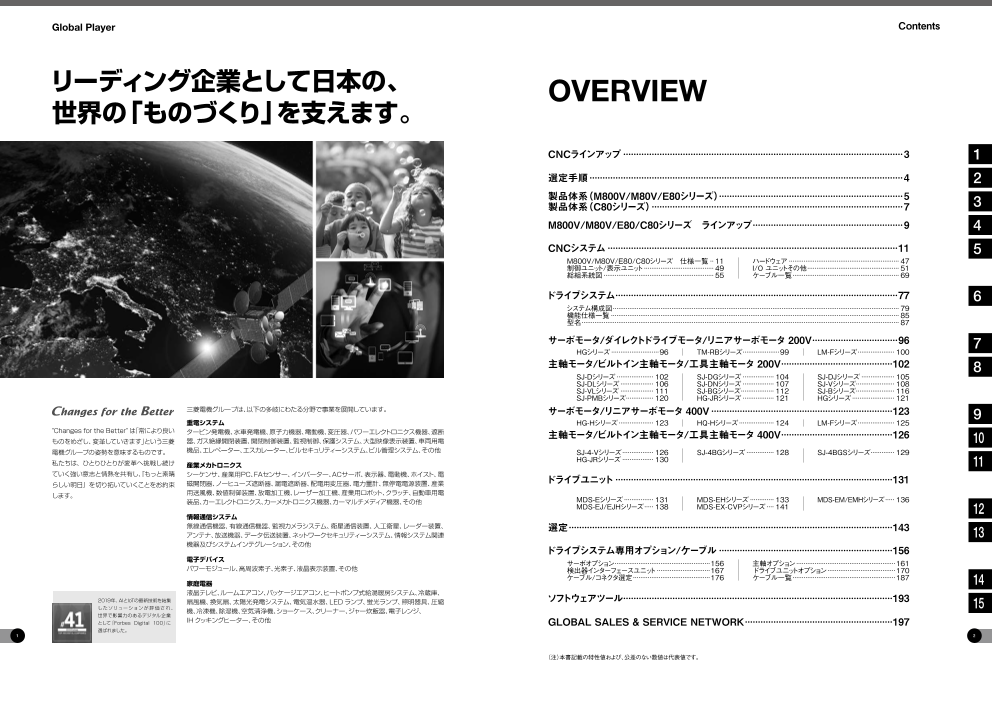
リーディング企業として日本の、 OVERVIEW
世界の「ものづくり」を支えます。
CNCラインアップ·············································································································3 1
選定手順··························································································································4 2
製品体系(M800V/M80V/E80シリーズ)·······································································5
製品体系(C80シリーズ)··································································································7 3
M800V/M80V/E80/C80シリーズ ラインアップ··························································9 4
CNCシステム·················································································································11 5
M800V/M80V/E80/C80シリーズ 仕様一覧··· 11· ハードウェア····························································· 47
制御ユニット/表示ユニット······································· 49· I/O·ユニットその他·················································· 51
総組系統図····························································· 55· ケーブル一覧··························································· 69
ドライブシステム·············································································································77 6
システム構成図···························································································································································· 79
機能仕様一覧······························································································································································ 85
型名············································································································································································· 87
サーボモータ/ダイレクトドライブモータ/リニアサーボモータ·200V·································96 7
HGシリーズ···························96 TM-RBシリーズ····················99 LM-Fシリーズ···················· 100
主軸モータ/ビルトイン主軸モータ/工具主軸モータ·200V···········································102 8
SJ-Dシリーズ····················· 102 SJ-DGシリーズ·················· 104 SJ-DJシリーズ··················· 105
SJ-DLシリーズ··················· 106 SJ-DNシリーズ·················· 107 SJ-Vシリーズ····················· 108
SJ-VLシリーズ··················· 111 SJ-BGシリーズ·················· 112 SJ-Bシリーズ····················· 116
SJ-PMBシリーズ··············· 120 HG-JRシリーズ·················· 121 HGシリーズ························ 121
三菱電機グループは、以下の多岐にわたる分野で事業を展開しています。 サーボモータ/リニアサーボモータ·400V·······································································123 9
重電システム HG-Hシリーズ···················· 123 HQ-Hシリーズ···················· 124 LM-Fシリーズ···················· 125
"Changes for the Better" は「常により良い タービン発電機、水車発電機、原子力機器、電動機、変圧器、パワーエレクトロニクス機器、遮断 主軸モータ/ビルトイン主軸モータ/工具主軸モータ·400V···········································126
ものをめざし、変革していきます」という三菱 器、ガス絶縁開閉装置、開閉制御装置、監視制御、保護システム、大型映像表示装置、車両用電 10
電機グループの姿勢を意味するものです。 機品、エレベーター、エスカレーター、ビルセキュリティーシステム、ビル管理システム、その他 SJ-4-Vシリーズ·················· 126 SJ-4BGシリーズ················ 128 SJ-4BGSシリーズ············· 129
私たちは、ひとりひとりが変革へ挑戦し続け HG-JRシリーズ·················· 130
産業メカトロニクス 11
ていく強い意志と情熱を共有し『、もっと素晴 シーケンサ、産業用PC、FAセンサー、インバーター、ACサーボ、表示器、電動機、ホイスト、電
らしい明日』を切り拓いていくことをお約束 磁開閉器、ノーヒューズ遮断器、漏電遮断器、配電用変圧器、電力量計、無停電電源装置、産業 ドライブユニット············································································································131
します。 用送風機、数値制御装置、放電加工機、レーザー加工機、産業用ロボット、クラッチ、自動車用電
装品、カーエレクトロニクス、カーメカトロニクス機器、カーマルチメディア機器、その他 MDS-Eシリーズ················· 131 MDS-EHシリーズ·············· 133 MDS-EM/EMHシリーズ······ 136
MDS-EJ/EJHシリーズ····· 138 MDS-EX-CVPシリーズ····· 141 12
情報通信システム
無線通信機器、有線通信機器、監視カメラシステム、衛星通信装置、人工衛星、レーダー装置、 選定·····························································································································143
アンテナ、放送機器、データ伝送装置、ネットワークセキュリティーシステム、情報システム関連 13
機器及びシステムインテグレーション、その他
ドライブシステム専用オプション/ケーブル····································································156
電子デバイス サーボオプション····················································156· 主軸オプション·······················································161
パワーモジュール、高周波素子、光素子、液晶表示装置、その他 検出器インターフェースユニット······························167· ドライブユニットオプション······································170
ケーブル/コネクタ選定··········································176· ケーブル一覧·························································187
家庭電器 14
液晶テレビ、ルームエアコン、パッケージエアコン、ヒートポンプ式給湯暖房システム、冷蔵庫、
2019年、AIとIoTの最新技術を結集 扇風機、換気扇、太陽光発電システム、電気温水器、LED ランプ、蛍光ランプ、照明器具、圧縮 ソフトウェアツール········································································································193
したソリューション が 評 価 さ れ、 15
機、冷凍機、除湿機、空気清浄機、ショーケース、クリーナー、ジャー炊飯器、電子レンジ、
世界で影響力のあるデジタル企業
として「Forbes Digital 100」に IH クッキングヒーター、その他 GLOBAL·SALES·&·SERVICE·NETWORK·························································197
選ばれました。
1 2
(注)本書記載の特性値および、公差のない数値は代表値です。
Page3
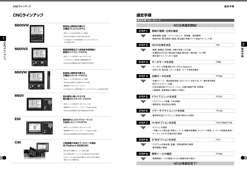
CNCラインアップ 選定手順
CNCラインアップ 選定手順
選定手順フローチャート
M800VW 拡張性と柔軟性を備えた NC仕様選定開始!
分離型プレミアムモデル
STEP 1 機械の種類、仕様を確認
・制御ユニットと表示器が独立した分離型
・Windowsを搭載した拡張性の高い表示器 ・機械種類:·旋盤/マシニングセンタ/研削盤/専用機等
1 ・4つの拡張スロットを標準装備オプションカードスロットに ・制御内容、要求精度の確認、周辺軸の有無(ワーク供給やターレット等)
よる拡張性を実現
STEP 2 NCの仕様を決定 P4 2
M800VS 高速高精度加工と多軸多系統制御に ・軸数、軸構成、系統数、主軸の有無、I/O点数
最適なハイグレードモデル ・位置検出方式及び検出能力確認(絶対値/相対値、パルス数)
・制御ユニットと表示器が一体のパネルイン型 ・表示器サイズ、キーボード選択
・マルチCPUにより高性能と高機能描画を両立
・Windows非搭載型表示器で快適な操作性を実現 STEP 3 サーボモータを決定 P96
・サーボモータ容量選定(NC·Servo·Selection)
・外形寸法、検出器、スケール有無、ブレーキ有無を確認
M80VW 拡張性と柔軟性を備えた
分離型スタンダードモデル STEP 4 主軸モータを決定 P102
・制御ユニットと表示器が独立した分離型
・主軸のベース/最高回転速度、出力、トルク、外形寸法、キー溝有無を確認
・Windowsを搭載した拡張性の高い表示器
・枠付·or·ビルトイン主軸
・機種選定しやすいパッケージタイプ
・付加仕様有無(オリエンテーション、主軸C軸要不要、同期等)
・2つの拡張スロットを標準装備オプションカードスロットによる拡張性を実現 ・C軸精度、速度確認(C軸有りの場合)
M80V 高生産性と使いやすさを STEP 5 ドライブユニットを決定 P131
兼ね備えたスタンダードモデル
・ドライブユニット容量、寸法を確認
・制御ユニットと表示器が一体のパネルイン型 ・電源回生/抵抗回生を確認
・機種選定しやすいパッケージタイプ ( TypeA/TypeB)
・Windows非搭載型表示器で快適な操作性を実現 STEP 6 パワーサプライユニットを決定 P143
・電源回生型ドライブユニット使用の場合のみ選定
E80 簡単操作とコストパフォーマンス
を追求したシンプルモデル STEP 7 H/Wオプションを決定 P47,P69,P176
・制御ユニットと表示器が一体のパネルイン型 ・オプションの確認
・機種選定しやすいパッケージタイプ ( TypeA/TypeB) (· 手動パルス発生器、同期エンコーダ、振動切削機能、ネットワーク有無、シーケンサ接続有無等)
・Windows非搭載型表示器で快適な操作性を実現 ・ケーブル、コネクタ手配内容の確認
STEP 8 S/Wオプションを決定 P11
C80 三菱電機の先進テクノロジーを集結
iQ Platform 対応型CNC ・プログラム記憶本数(容量)、変数組数等の確認
・要求機能の確認
・MELSECの豊富なユニットと容易に連携
・PLCはMELSECシーケンサ、表示器はGOT2000を使用 STEP 9 開発ツールの確認 P193
3 ・1台のベースに3台のC80が搭載でき、最大21系統/48軸の 4
制御システムが構築可能 ・画面開発ツールの確認(カスタム画面作成の場合)
NC仕様選定完了!
選定手順
CNCラインアップ
Page4
製品体系(M800V/M80V/E80シリーズ) 製品体系(M800V/M80V/E80シリーズ)
製品体系(M800V/M80V/E80シリーズ)
Ethernet
機械組立・調整用ソフトウェア
M800VS/M80V/E80シリーズ M800VW/M80VWシリーズ Field Network PCサーバ ••NC•Analyzer2
••CC-Link ••生産管理システム ••NC•Configurator2
••PROFIBUS-DP 電気設計用ソフトウェア
••PROFINET •
••EtherNet/IP •NC•Designer2
•
••CC-Link•IEフィールドネットワーク •NC•Trainer2plus
••CC-Link•IEフィールドネットワーク 運転・保守用ソフトウェア
3 Basic ••NC•Trainer2
••FL-net ••NC•Explorer 3
USBメモリ USBメモリ ••NC•Monitor2
••三菱電機CNC用通信ソフトウェア•
SDカード SDカード (FCSB1224W000)
••iQ•Care•Remote4U
••NC•Machine•Tool•Optimizer
SDカード
EcoMonitorLight
表示器一体型制御ユニット 表示器&キーボード 制御ユニット リモート
&キーボード I/Oユニット
サーミスタ
入力ユニット
停電保護ユニット
••MDS-D/DH-PFU
手動パルス
発生器 機械操作パネル
ドライブユニット
••MDS-E/EHシリーズ
••MDS-EJ/EJHシリーズ
••MDS-EM/EMHシリーズ
パワーサプライ
ユニット
••MDS-E/EH-CV
••MDS-EX-CVP
主軸モータ
••SJ-Dシリーズ
工具主軸モータ サーボモータ ••SJ-DGシリーズ ACリアクトル
•
•HGシリーズ •HGシリーズ •SJ-DLシリーズ
• • MC
•
•HG-JRシリーズ •LM-Fシリーズ •SJ-DNシリーズ
• •
••SJ-DJシリーズ
••TM-RBシリーズ AC電源
••SJ-BGシリーズ
別注文品:NC装置の付属品として準備をしておりませんので、別途、代理店などからご購入ください。
5 6
製品体系(M800V/M80V/E80シリーズ)
製品体系(M800V/M80V/E80シリーズ)
Page5
製品体系(C80シリーズ) 製品体系(C80シリーズ)
製品体系(C80シリーズ)
Ethernet
機械組立・調整用
制御装置 パソコンサーバ ソフトウェア
MELSEC iQ-Rシリーズ ・生産管理システム ・GX Works3
・GT Works3
・NC Analyzer2
Field Network ・NC Con gurator2
・CC-Link IE フィールドネットワーク 運転・保守用ソフトウェア
3 ・FL-net ・NC Explorer
・PROFIBUS-DP 3
・ ・
PROFINET NC Monitor2
・三菱電機CNC用通信ソフトウェア
( FCSB1224W000)
・iQ Care Remote4U
表示器 ・NC Machine Tool Optimizer
・GOT2000シリーズ ※1
C80
手動パルス発生器
分線
I/Oユニット
停電保護ユニット
・MDS-D/DH-PFU
USBキーボード 機械操作パネル 手動パルス ドライブユニット ※2
※機械メーカ殿作成 発生器 ・MDS-E/EHシリーズ
・MDS-EJ/EJHシリーズ
・MDS-EM/EMHシリーズ
パワーサプライ
ユニット
・MDS-E/EH-CV
・MDS-EX-CVP
主軸モータ ※2
・SJ-Dシリーズ
・SJ-DGシリーズ
サーボモータ ※2
工具主軸モータ ・SJ-DLシリーズ リアクトル
AC
※2 ・ HGシリーズ ・SJ-DNシリーズ MC
・ HGシリーズ ・ LM-Fシリーズ ・SJ-DJシリーズ
・ HG-JRシリーズ ・TM-RBシリーズ ・SJ-BGシリーズ AC電源
※1 対象機種は「CNCシステム 制御ユニット/表示ユニット」を参照してください。
※2 ドライブユニット、モータはCNC専用品をご使用ください。
別注文品:NC装置の付属品として準備をしておりませんので、別途、代理店などからご購入ください。
7 8
製品体系(C80シリーズ)
製品体系(C80シリーズ)
Page6
M800V/M80V/E80/C80シリーズ ラインアップ M800V/M80V/E80/C80シリーズ ラインアップ
M800V/M80V/E80/C80シリーズ ラインアップ
旋盤系 マシニングセンタ系
1 1
1 (表示器/制御ユニット分離型)(表示器/制御ユニット一体型)(表示器/制御ユニット分離型)(表示器/制御ユニット一体型)(表示器/制御ユニット一体型) (表示器/制御ユニット分離型)(表示器/制御ユニット一体型)(表示器/制御ユニット分離型)(表示器/制御ユニット一体型)(表示器/制御ユニット一体型) 1
M800VWシリーズ M800VSシリーズ M80VWシリーズ M80Vシリーズ E80シリーズ C80シリーズ M800VWシリーズ M800VSシリーズ M80VWシリーズ M80Vシリーズ E80シリーズ C80シリーズ
1 機種名 機種名
M850VW M830VW M850VS M830VS ― TypeA TypeB TypeA TypeB ― M850VW M830VW M850VS M830VS ― TypeA TypeB TypeA TypeB ― 1
最大制御軸数· 32 32 13 13 9 8 6 16 最大制御軸数·
(NC軸+主軸+PLC軸) (NC軸+主軸+PLC軸) 32 32 11 11 9 6 4 16
4 最大NC軸数(系統合計) 32 32 10 10 7 5 4 16 最大NC軸数(系統合計) 16 16 9 9 5 5(*1) 3 16 4
制 最大主軸軸数 8 8 6 6 4 3 3 7 制 最大主軸軸数 6 6 4 4 2 1 7
御 御
軸 最大PLC軸数 8 8 6 6 3 8 軸 最大PLC軸数 8 8 6 6 2 0 8
数 数
最大PLC割り出し軸数 8 8 4 4 1 1 8 最大PLC割り出し軸数 8 8 4 4 1 0 8
同時輪郭制御軸数 8 4 8 4 4 4 4 4 同時輪郭制御軸数 8 4 8 4 4 4 4 3 4
系統内最大NC軸数 12 12 8 8 5 5 4 8 系統内最大NC軸数 12 12 8 8 5 5(*1) 3 8
最大系統数(メイン+サブ) 8 8 4 4 2 1 7 最大系統数(メイン+サブ) 2 2 2 2 1 1 7
最大メイン系統数 8 8 2 2 1 7 最大メイン系統数 2 2 2 2 1 1 7
最大サブ系統数 8 8 2 2 1 ― 2 最大サブ系統数 2 2 ― ― ― ―
制御ユニット内高速プログラムサーバ運転 有 ― 有 ― ― ― 制御ユニット内高速プログラムサーバ運転 有 ― 有 ― ― ―
表示器ユニット内高速プログラムサーバ運転 有 有 有 有 有 ― 表示器ユニット内高速プログラムサーバ運転 有 有 有 有 有 ―
FTP高速プログラムサーバ運転 ― 有 FTP高速プログラムサーバ運転 ― 有
前面SDカード運転 有 ― 前面SDカード運転 有 ―
前面USBメモリ運転 有 ― 前面USBメモリ運転 有 ―
最小指令単位 1nm 1nm 0.1μm 0.1μm 0.1μm 0.1μm 最小指令単位 1nm 1nm 0.1μm 0.1μm 0.1μm 1μm 0.1μm
最小制御単位 1nm 最小制御単位 1nm
工具オフセット組数 999 999 256 256 99 99 256 工具オフセット組数 999 999 400 400 200 99 400
2,000KB 2,000KB 500KB 500KB 230KB 2,000KB 2,000KB 2,000KB 500KB 500KB 500KB 2,000KB
最大プログラム記憶容量 (5,120m) (5,120m) (1,280m) (1,280m) (600m) (5,120m) 最大プログラム記憶容量 (5,120m) (5,120m) (1,280m) (1,280m) (1,280m) (5,120m)
(1,000本) (1,000本) (1,000本) (1,000本) (400本) (1,000本) (1,000本) (1,000本) (1,000本) (1,000本) (1,000本) (1,000本)
最大PLCプログラム記憶容量
[Kステップ] 512 512 64 64 32 20 有(MELSEC) 最大PLCプログラム記憶容量
[Kステップ] 512 512 64 64 32 20 有(MELSEC)
マルチプロジェクト[格納PLCプロジェクト数] 6 6 3 3 2 2 ― マルチプロジェクト[格納PLCプロジェクト数] 6 6 3 3 2 2 ―
対話式サイクル挿入 有 ― 対話式サイクル挿入 有 ―
高速加工モードI·最大[kBPM] 33.7 33.7 33.7 33.7 ― ― 33.7 高速加工モードI·最大[kBPM] 33.7 33.7 33.7 33.7 16.8 ― 33.7
高速加工モードII·最大[kBPM] 168 168 101 67.5 ― ― 67.5 高速加工モードII·最大[kBPM] 168 168 101 101 ― 67.5
高速・高精度制御I·最大[kBPM] 67.5 67.5 33.7 33.7 ― ― 33.7 高速・高精度制御I·最大[kBPM] 67.5 67.5 33.7 33.7 ― 33.7
高速・高精度制御II·最大[kBPM] 168 168 101 67.5 ― ― 67.5 高速・高精度制御II·最大[kBPM] 168 168 101 101 ― 67.5
高速・高精度制御III·最大[kBPM] ― 高速・高精度制御III·最大[kBPM] 540 540 202 202 ― ― 135
高精度制御 有 高精度制御 有 ― 有
SSS制御(Super·Smooth·Surface) 有 ―(eSSS搭載) ― SSS制御(Super·Smooth·Surface) 有 ―(eSSS搭載) ― 有
トレランス制御 有 ― トレランス制御 有 ― 有
CC-Lin(k マスタ/ローカル) 有 有(MELSEC) CC-Lin(k マスタ/ローカル) 有 有(MELSEC)
PROFIBUS-DP(マスタ) 有 ― PROFIBUS-DP(マスタ) 有 ―
MESインタフェースライブラリ 有 ― MESインタフェースライブラリ 有 ―
スマート安全監視 有 ― 有 スマート安全監視 有 ― 有
19型タッチパネル/19型横タッ 19型タッチパネル/15型 19型タッチパネル/19型横タッチ 19型タッチパネル/15型 12.1型タッチパネル/10.4型タッ 19型タッチパネル/19型横タッ 19型タッチパネル/15型 19型タッチパネル/19型横タッチ 19型タッチパネル/15型 12.1型タッチパネル/10.4型タッ
表示器(*2()*3) チパネル/15型タッチパネル/ タッチパネル/10.4型タッ パネル/15型タッチパネル/10.4 タッチパネル/10.4型タッチ 8.4型 チパネル/8.4型タッチパネル/ 表示器(*2()*3) チパネル/15型タッチパネル/ タッチパネル/10.4型タッ パネル/15型タッチパネル/10.4 タッチパネル/10.4型タッチ 8.4型 チパネル/8.4型タッチパネル/
10.4型タッチパネル(選択仕様) チパネル(選択仕様) 型タッチパネル/8.4型(選択仕様) パネル/8.4型(選択仕様) 5.7型タッチパネル(選択仕様) 10.4型タッチパネル(選択仕様) チパネル(選択仕様) 型タッチパネル/8.4型(選択仕様) パネル/8.4型(選択仕様) 5.7型タッチパネル(選択仕様)
Windows®10·搭載(*2) 有 ― 有 ― ― ― Windows®10·搭載(*2) 有 ― 有 ― ― 有
9 ※オプション仕様を含む最大仕様で記載しています。オプションの詳細は仕様一覧を参照してください。 10
(*1)回転軸は1軸まで
(*2)詳細は、「CNCシステム 制御ユニット/表示ユニット」を参照してください。
(*3)M800VSシリーズおよびM80Vシリーズの19型タッチパネルは開発中の製品のため詳細は弊社までお問合せください。
M800V/M80V/E80/C80シリーズ ラインアップ
· · ·
· · ·
M800V/M80V/E80/C80シリーズ ラインアップ
Page7
M800V/M80V/E80/C80シリーズ 仕様一覧 M800V/M80V/E80/C80シリーズ 仕様一覧
CNCシステム M800V/M80V/E80/C80シリーズ 仕様一覧
Standard Optional Selection Specifications of separated-
type display are classified with “Windows-based” and non- 標準 オプション 選択 [M800V/M80V]S/W ver.A2 [E80]S/W ver.F7 [C80]S/W ver.B9 [M800V/M80V]S/W ver.A2 [E80]S/W ver.F7 [C80]S/W ver.B9
Windows-based
旋盤系 マシニングセンタ系
使用 class 分類 M800VW M800VS M80VW M80V E80 C80 M800VW M800VS M80VW M80V E80 C80 General explanation
M850VW M830VW M850VS M830VS ー M80V M80V E80 E80 M80V M80V E80 E80 概略説明
TypeA TypeB TypeA TypeB ー M850VW M830VW M850VS M830VS ー TypeA TypeB TypeA TypeB ー
1 Control axes 1 制御軸
1 Control axes 1 制御軸に関すること
1 Number of basic control axes (NC axes) 1 基本制御軸数(NC軸) 2 2 2 2 2 2 2 2 2 2 3 3 3 3 3 3 3 3 3 3 The NC axis, spindle, and PLC axis are generically called the control axis.
2 最大制御軸数(NC軸+主軸+PLC軸) 16 16 16 16 16 16 16 16
2 Max. number of axes (NC axes + Spindles + PLC axes) 13 13 9 8 6 16 11 11 9 6 4 16 NC軸、主軸、PLC軸を総称して制御軸と呼びます。 The NC axis can be manually or automatically operated using a machining
32 32 32 32 32 32 32 32 NC軸とは手動運転や加工プログラムからの自動運転ができる軸です。 program.
16 16 16 16 PLC軸とはシーケンスプログラムから制御ができる軸です。 The PLC axis can be controlled using a sequence program.
1 Max. number of NC axes (in total for all the part systems) 1 最大NC軸数(系統合計) 10 10 7 5 4 16 16 16 16 16 9 9 5 5* 3 16 軸数は最大制御軸数の範囲内で、かつNC軸、主軸、PLC軸のそれぞれの最大数を The number of axes that is within the max. number of control axes, and that does
32 32 32 32 超えない範囲で使用できます。 not exceed the max. number given for the NC axis, spindle and PLC axis, can be
2 Max. number of spindles 2 最大主軸軸数 8 8 8 8 6 6 4 3 3 7 6 6 6 6 4 4 2 1 1 7 * 回転軸は1軸まで used.
3 Max. number of PLC axes 3 最大PLC軸数 8 8 8 8 6 6 6 3 3 8 8 8 8 8 6 6 6 2 0 8 *1 Rotary axis up to 1 axis
4 Max. number of PLC indexing axes 4 最大PLC割り出し軸数 8 8 8 8 4 4 4 1 1 8 8 8 8 8 4 4 4 1 0 8 割り出し軸として使用することができるPLC軸数です。 The number of PLC axes available to be used as indexing axis.
5 Number of simultaneous contouring control axes 5 同時輪郭制御軸数 8 4 8 4 4 4 4 4 4 4 8 4 8 4 4 4 4 4 3 4 同時に補間制御が可能な軸数です。 Number of axes with which simultaneous interpolation control is possible.
6 系統内最大NC軸数 8 8 8 8 8 8 8 8
6 Max. number of NC axes in a part system 8 8 5 5 4 8 8 8 5 5* 3 8 同一系統内で制御できる最大NC軸数です。 Max. number of NC axes possible to control in the same part system.
12 12 12 12 12 12 12 12 * 回転軸は1軸まで * Rotary axis up to 1 axis
7 Axis name extension 7 軸名称拡張 — — — — NC制御軸に絶対値指令/増分値指令を行うための軸名称(指令軸名称)を英字2 The axis name (command axis name) to issue the absolute/incremental command
文字に拡張できます。 to NC control axis can be expanded to two letters.
2 Control part system 2 制御系統に関すること
1 Standard number of part systems 1 標準系統数 1 1 1 1 1 1 1 1 1 1 1 1 1 1 1 1 1 1 1 1 標準1系統です。 One part system is the standard.
4 4 4 4
2 Max. number of part systems (main + sub) 2 最大系統数(メイン+サブ) 4 4 2 1 1 7 2 2 2 2 2 2 1 1 1 7
8 8 8 8 [M800V/M80V/E80] [M800/M80/E80]
4 4 4 4
1 Max. number of main part systems 5 1 最大メイン系統数 2 2 2 1 1 7 2 2 2 2 2 2 1 1 1 7 旋盤系は最大8系統、マシニングセンタ系は最大2系統です。 5 Up to eight part systems for a lathe system, and up to two part systems for a
[C80] machining center system.
8 8 8 8
最大7系統です。 [C80]
2 Max. number of sub part systems 2 最大サブ系統数 4 4 4 4 Up to seven part systems.
2 2 1 — — 2 2 2 2 2 — — — — — —
8 8 8 8
3 Control axes and operation modes 3 制御軸と運転モード
1 Tape (RS-232C input) mode 1 テープ(RS-232C入力)運転 — — CNCに内蔵されているRS-232Cインターフェースからの加工プログラムデータで運転 In this mode, operation is performed using the machining program data from the
します。 RS-232C interface built in the CNC unit.
2 Memory mode 2 メモリ運転 CNC内部に記憶された加工プログラムを運転します。 Machining programs stored in the memory of the CNC module are run.
3 MDI mode 3 MDI運転 CNC内部に記憶されたMDIデータを実行します。 MDI data stored in the memory of the CNC unit are executed.
4 High-speed program server mode 4 高速プログラムサーバ運転
1 Control unit-side High-speed program server mode 1 制御ユニット内高速プログラムサーバ運転 — — — — — — — — — — — — — — 制御ユニットのSDカードインターフェースにSDカードを実装して、SDカード内に格納さ The machining program stored in SD card can be operated by installing a SD card
れた加工プログラムを運転できます。 in the control unit SD card interface.
The machining program stored in the built-in disk of the display unit can be
表示ユニット内蔵ディスク内に格納された加工プログラムを運転できます。 operated.
2 Display unit-side High-speed program server mode 2 表示器ユニット内高速プログラムサーバ運転 — — 表示ユニット内蔵ディスクは、M800VW/M80VW(Windows搭載型表示器)の場 The built-in disk of the display unit is mounted in the personal computer for
合はパソコンユニットに装着されています。M800VS/M80V/E80 の場合は、表示 M800VW/M80VW (Windows-based display unit). For M800VS/M80V/E80,
ユニット背面のSD カードI/F に装着したSD カードです。 the SD card inserted into SD card I/F on the back of the display unit is equivalent to
the built-in disk of the display unit.
3 FTP high-speed program server mode 3 FTP高速プログラムサーバ運転 — — — — — — — — — — — — — — — — — — CNCCPU内の大容量バッファメモリに、イーサネット内のFTP機能を利用してFTP This function allows high-speed transfer of machining programs from the FTP
サーバーから加工プログラムを高速転送し、運転する機能です。 server to the large-capacity buffer memory in CNC CPU via Ethernet to execute
the program.
5 Front-side SD card mode 5 前面SDカード運転 — — 前面SDカードI/Fに装着したSDカード内に格納された加工プログラムを運転できま The machining program stored in a SD card can be operated. This SD card is
す。 installed to the front-side SD card I/F.
6 Front-side USB memory mode 6 前面USBメモリ運転 — — 前面USBメモリI/F に装着したUSBメモリ内に格納された加工プログラムを運転でき The machining program stored in a USB memory can be operated. This USB
ます。 memory is installed to the front-side USB memory I/F.
2 Input command 2 入力指令
1 Data increment 1 データ単位に関すること
1 Least command increment 1 最小指令単位 制御装置内で扱うデータの単位の種類には入力設定単位、指令単位があります。 The data increment handled in the controller includes the input setting increment
いずれもパラメータで指定します。 and command increment. Each type is set with parameters.
Least command increment 1µm 最小指令単位 1μm 直線軸で0.001mm、回転軸で0.001°の指令が可能です。 Possible to command in increments of 0.001mm (linear axis) and 0.001° (rotary
axis).
Least command increment 0.1µm 最小指令単位 0.1μm — 直線軸で0.0001mm、回転軸で0.0001°の指令が可能です。 Possible to command in increments of 0.0001mm (linear axis) and 0.0001° (rotary
axis).
Least command increment 0.01µm (10nm) 最小指令単位 0.01μm(10nm) — — — — — — — — — — — — 直線軸で0.00001mm、回転軸で0.00001°の指令が可能です。 Possible to command in increments of 0.00001mm (linear axis) and 0.00001° (rotary
axis).
Least command increment 0.001µm (1nm) 最小指令単位 0.001μm(1nm) — — — — — — — — — — — — 直線軸で0.000001mm、回転軸で0.000001°の指令が可能です。 Possible to command in increments of 0.000001mm (linear axis) and 0.000001°
(rotary axis).
2 Least control increment 2 最小制御単位 最小制御単位はCNC内部の演算精度を決める単位です。 The least control increment determines the CNC's internal operation accuracy.
Least control increment 0.01µm (10nm) 最小制御単位 0.01μm(10nm) 直線軸で0.00001mm、回転軸で0.00001°の制御が可能です。 Possible to control in increments of 0.00001mm (linear axis) and 0.00001° (rotary
axis).
Least control increment 0.001µm (1nm) 最小制御単位 0.001μm(1nm) 直線軸で0.000001mm、回転軸で0.000001°の制御が可能です。 Possible to control in increments of 0.000001mm (linear axis) and 0.000001° (rotary
axis).
3 Indexing increment 3 割出し単位 回転軸において、指令値を制約する機能です。 This function limits the command value for the rotary axis.
2 Unit system 2 単位系に関すること
The unit systems of the data handled in the controller include the metric system
1 Inch / Metric changeover 1 インチ/メトリック切換え 制御装置内で扱うデータの単位系はメトリック単位系、インチ単位系の2種類があり、
パラメータおよび加工プログラムにより指定ができます。 and inch system. The type can be designated with a parameter and a machining
program.
2 Input command increment tenfold 2 入力指令単位10倍 — — — — — — — — — — パラメータ指定により、プログラムの指令単位に任意の倍率を乗じて使用することが The program's command increment can be multiplied by an arbitrary scale with the
できます。指令単位に小数点を使用していない場合に有効です。 parameter designation. This function is valid when a decimal point is not used for
the command increment.
3 Program format 3 プログラムフォーマット
1 Program format 1 プログラムフォーマット Gコード(プログラム)のフォーマットです。 G code (program) format
1 Format 1 for Lathe (G Code List 2, 3) 1 旋盤用フォーマット1(Gコード系列2,3) — — — — — — — — — —
2 Format 2 for Lathe (G Code List 4, 5) 2 旋盤用フォーマット2(Gコード系列4,5) — — — — — — — — — — 旋盤系のGコード系列です。Gコード系列はパラメータで選択します。 G code list for the lathe system. The G code list is selected by parameter.
3 Special format for lathe (G Code List 6, 7) 3 旋盤用特殊フォーマット(Gコード系列6,7) — — — — — — — — — —
4 Format 1 for Machining center 4 マシセン用フォーマット1 — — — — — — — — — —
マシニングセンタ系のGコード系列です。Gコード系列はパラメータで選択します。 G code list for the machining center system. The G-code list is selected by
5 Format 2 for Machining center (M2 format) 5 マシセン用フォーマット2(M2フォーマット) — — — — — — — — — — — — parameter.
旋削用固定サイクル(G77~G79)、複合型旋削用固定サイクル(G71~G76)、穴 The formats of the fixed cycle for turning machining (G77 to G79), compound type
6 MITSUBISHI CNC special format 6 三菱数値制御装置 特殊フォーマット — — — — — — — — — — あけ用固定サイクル(G80~G89)のフォーマットを三菱数値制御装置特殊フォーマッ fixed cycle for turning machining (G71 to G76) and fixed cycle for drilling (G80 to
トに切り換えることができます。 G89) can be switched to the MITSUBISHI CNC special formats.
Gコード、または、PLC信号により、プログラムフォーマット(Gコード系列)を切換える機 This function is designed to switch the program format (G code list) using G codes
2 Program format switch 2 プログラムフォーマット切換え — — — — — — — — — — — — — — — — 能です。旋盤ベースの複合加工機において、M系Gコード系列に切り換えることで、 or PLC signal. When you run a lathe-based multi-tasking machine, and if you
CAMで作成した自由曲面加工用のプログラムをそのまま使用できます。 change to the G code list of machining center system, you can use a free-curved
surface machining program made with CAM without modifying the program.
4 Command value 4 指令数値に関すること
For the decimal point input type 1, the unit of the last digit of a command without
小数点入力Ⅰでは、小数点を使用しない指令の最小桁は最小指令単位と同じになり a decimal point is the same as that of the least command increment. For decimal
1 Decimal point input 1,2 11 1 小数点入力I,II ます。小数点入力Ⅱでは、小数点がない場合最終桁は、メトリックモード時はmm単位、 12 point input type 2, the last digit of a command without a decimal point is interpreted
インチモード時はinch単位で、時間指定は秒単位となります。 in millimeters during the metric mode, in inches in the inch mode, or in seconds for
a time-based command.
When axis coordinate data are issued in a machining program command, either
加工プログラム指令において軸座標データを与えるとき、現在位置からの相対距離を the incremental command method, which commands a relative distance from
2 Absolute / Incremental command 2 アブソリュート/インクレメンタル指令 指令するインクレメンタル指令方式と予め定められた座標系の指定位置へ移動する the current position, or the absolute command method, which commands a
アブソリュート指令方式とが選択できます。 movement to a designated position in a predetermined coordinate system, can be
selected.
CNCシステム
CNCシステム
Page8
M800V/M80V/E80/C80シリーズ 仕様一覧 M800V/M80V/E80/C80シリーズ 仕様一覧
Standard Optional Selection Specifications of separated-
type display are classified with “Windows-based” and non- 標準 オプション 選択 [M800V/M80V]S/W ver.A2 [E80]S/W ver.F7 [C80]S/W ver.B9 [M800V/M80V]S/W ver.A2 [E80]S/W ver.F7 [C80]S/W ver.B9
Windows-based
旋盤系 マシニングセンタ系
使用 class 分類 M800VW M800VS M80VW M80V E80 C80 M800VW M800VS M80VW M80V E80 C80 General explanation
M850VW M830VW M850VS M830VS ー M80V M80V E80 E80 ー M850VW M830VW M850VS M830VS ー M80V M80V E80 E80 概略説明
TypeA TypeB TypeA TypeB TypeA TypeB TypeA TypeB ー
パラメータにより、軸の指令値を半径指定または直径指定に切り換えられます。直径 The designation method of an axis command value can be changed over with
3 Diameter / Radius designation 3 直径/半径指定 — — — — — — — — — — 指定を選択すると選択された軸の長さのスケールは2倍に扱われます。(指令された量 parameters between the radius designation or diameter designation. When the
の1/2だけ移動します。) diameter designation is selected, the scale of the length of the selected axis is
doubled. (moves only half (1/2) the commanded amount)
4 Diameter / Radius designation switch 4 直径/半径指定切替 — — — — — — — 本機能は、Gコード指令により軸毎の直径/半径指定を任意のタイミングで切替えるこ Diameter/Radius designation switch function enables you to switch the diameter/
とを可能にする機能です。 radius designation of each axis using a G code at your desired timing.
3 Positioning / Interpolation 3 位置決め、補間機能
1 Positioning 1 位置決めに関すること
1 Positioning 1 位置決め プログラムにて与えられた移動指令値を、早送り速度にて高速位置決めを行う機能で This function carries out positioning at high speed using a rapid traverse rate with
す。 the travel command value given in the program.
2 Unidirectional positioning 2 一方向位置決め — — — — — — — — — — Gコード指令により、常にパラメータで定められた一方向から最終位置決めを行ないま The G code command always moves the tool to the final position in the direction
す。 determined by parameters.
2 Linear / Circular interpolation 2 直線/円弧補間に関すること
1 Linear interpolation 1 直線補間 プログラムにて与えられた移動指令値を、Fコードで指定された切削送り速度にて直 Linear interpolation is a function that moves a tool linearly by the travel command
線で移動させる機能です。 value supplied in the program at the cutting feedrate designated by the F code.
2 Circular interpolation (Center / Radius designation) 2 円弧補間(中心指定、半径指定) プログラムにて与えられた移動指令値により、平面上を円弧で移動させる機能です。 This function moves a tool along a circular arc on the plane selected by the travel
command value supplied in the program.
直交する3軸において、任意の2軸で円弧補間を行ない同時に他の1軸を円弧の回 With this function, any two of three axes intersecting orthogonally are made to
3 Helical interpolation 3 ヘリカル補間 転に同期して直線補間を行なう同時3軸制御です。大口径ねじや立体カムの加工が perform circular interpolation while the third axis performs linear interpolation in
行なえます。 synchronization with the arc rotation. This control can be exercised to machine
large-diameter screws or 3-dimensional cams.
4 Spiral / Conical interpolation 4 渦巻/円錐補間 — — — — — — — — — — — — — 始点と終点が同一円周上に無い円弧を渦巻状に円滑に補間します。 This function interpolates arcs where the start point and end point are not on the
5 5 circumference of the same circle into spiral shapes.
This function transfers the shape that is on the cylinder's side surface (shape
円筒側面にある形状(円筒座標系での形状)を平面に展開し、展開した形状を平面 yielded by the cylindrical coordinate system) onto a plane, and when the transferred
5 Cylindrical interpolation 5 円筒補間 — — の座標としてプログラム指令すると、機械加工時にCNCにて元の円筒座標の直線 shape is designated in the program in the form of plane coordinates, the shape is
軸と回転軸の移動に変換して輪郭制御する機能です。 converted into a movement along the linear and rotary axes of the original cylinder
coordinates, and the contours are controlled by means of the CNC unit during
machining.
直交座標軸でプログラムされた指令を、直線軸の移動(工具の移動)と回転軸の移動 This function converts the commands programmed by the orthogonal coordinate
6 Polar coordinate interpolation 6 極座標補間 — — — — — (ワークの回転)に変換して輪郭制御する機能です。ワーク外径に直線上の切欠部 axes into linear axis movements (tool movements) and rotary axis movements
を切削する場合、およびカムシャフトの研削等に有効な機能です。 (workpiece rotation) to control the contours. It is useful for cutting linear cutouts on
the outside diameter of the workpiece, grinding cam shafts, etc.
制御軸に直線軸(X, Z軸)と回転軸(C軸)を持つ旋盤において、ワークの端面又は When a lathe with linear axes (X, Z axes) and rotary axis (C axis) serving as the
7 Milling interpolation 7 ミーリング補間 — — — — — — — — — — 長手方向にミーリング加工を行えるようにした時、X, Z軸に直交するY軸を仮想し、ミー control axes is to perform milling at a workpiece end face or in the longitudinal
リング加工形状をX, Y, Zの直交座標系の指令としてプログラミングできるようにした direction of the workpiece, this function uses the hypothetical axis Y, which
のがミーリング機能です。 is at right angles to both the X and Z axes, to enable the milling shape to be
programmed as the X, Y and Z orthogonal coordinate system commands.
This function sets one of the axes of the helical interpolation or spiral interpolation,
直線軸を含むヘリカル補間または渦巻補間の1軸を仮想軸(実移動のない軸)として including a linear axis, as a hypothetical axis (axis with no actual movement),
8 Hypothetical axis interpolation 8 仮想軸補間 — — — — — — — — — — — — — — — — パルス分配させることにより、ヘリカル補間または渦巻補間を横(仮想軸)から見た補間 and performs pulse distribution. This enables SIN or COS interpolation, which
(SIN補間またはCOS補間)を行うことができます。 corresponds to the side view (view from the hypothetical axis) of the helical
interpolation or spiral interpolation.
3 Curve interpolation 3 曲線補間に関すること
インボリュート曲線に沿って工具を移動させることができます。また、インボリュート曲線 Tools can be moved along the involute curve. This function can also move a tool
に沿って工具を移動させながら、ヘリカル(螺旋)状に工具を移動させることができま helically (spirally) while moving the tool along the involute curve. This can be used
1 Involute interpolation 1 インボリュート補間 — — — — — — — — — — — — — — す。インボリュート歯車やコンプレッサ等のスクロール加工に使用することができ、微 for scroll machining of involute gears or compressors, and smooth accurate
小線分で指令した場合に発生するパスの段差、線分長の長短による加減速がなく滑 machining can be performed without stepping of path from the command by fine
らかに精度よく加工できます。 segment or without acceleration/deceleration by segment length.
2 Exponential interpolation 2 指数関数補間 — — — — — — — — — — — — 指数関数補間は、直線軸の移動に対して回転軸を指数関数状に変化させる補間で With this function, the rotary axis movement is changed into exponential functions
す。 vis-a-vis the linear axis movements.
微小線分加工プログラムで指令された点列を滑らかに通過するスプライン曲線を自 This function automatically generates spline curves that smoothly pass through
3 Spline interpolation (G05.1Q2 / G61.2) 3 スプライン補間(G05.1Q2/G61.2) — — — — — — — — — — — — — 動生成し、この曲線に沿って経路の補間を行います。これにより、高速でかつ高精度 rows of dots designated by a fine-segment machining program, and performs
な加工が実現できます。 interpolation for the paths along the curves. This enables high-speed and high-
accuracy machining.
曲面・曲線加工に利用されるNURBS曲線のパラメータ(階数・ウェイト・ノット・制御点) This function realizes NURBS curve machining by commanding NURBS curve
4 NURBS interpolation 4 NURBS補間 — — — — — — — — — — — — — — — — を指令するだけで、微小線分に置き換えることなく、NURBS曲線加工を実現する機 parameters (number of stages, weight, knot, control point). The path does not
能です。 need to be replaced with fine segments.
5 3-dimensional circular interpolation 5 三次元円弧補間 — — — — — — — — — — — — — — 三次元空間上に指定された3点(始点、中間点、終点)によって一義に定まる円弧形 An arc shape determined by three points (start point, intermediate point, end point)
状を加工することができます。 designated in the three-dimensional space can be machined.
6 Spline interpolation2 (G61.4) 6 スプライン補間2(G61.4) — — — — — — — — — — — — — トレランス(許容誤差)の範囲内を滑らかに通過する曲線を自動生成し、この曲線に This function automatically generates curves that smoothly pass in the tolerance
沿った経路上を動作する機能です。滑らかな加工を実現できます。 error range, and moves on the paths along the curves. This enables smooth
machining.
4 Feed 4 送り
1 Feedrate 1 速度に関すること
1 Rapid traverse rate (m / min) 1 早送り速度(m/min) 1000 1000 1000 1000 1000 1000 1000 1000 1000 1000 1000 1000 1000 1000 1000 1000 1000 1000 1000 1000 早送り速度は、パラメータにより各軸独立に設定できます。 The rapid traverse rate can be set independently for each axis using parameters.
2 Cutting feedrate (m / min) 2 切削送り速度(m/min) 1000 1000 1000 1000 1000 1000 1000 1000 1000 1000 1000 1000 1000 1000 1000 1000 1000 1000 1000 1000 切削指令の送り速度を指定するもので、主軸1回転あたりの送り量または1分間あた This function specifies the feedrate of the cutting commands, and gives a
りの送り量を指定します。 command for a feed amount per spindle rotation or feed amount per minute.
手動送り速度は、手動運転のジョグモード、インクレメンタル送りモードの送り速度、お The manual feedrates are designated as the feedrate in jog mode or incremental
3 Manual feedrate (m / min) 3 手動送り速度(m/min) 1000 1000 1000 1000 1000 1000 1000 1000 1000 1000 1000 1000 1000 1000 1000 1000 1000 1000 1000 1000 よび、自動運転でドライランオン時の送り速度を指定します。手動送り速度は外部信 feed mode for manual operation and the feedrate during dry run ON for automatic
号で設定します。 operation. The manual feedrates are set using external signals.
4 Rotary axis command speed tenfold 4 回転軸指令速度10倍 イニシャルインチ時に回転軸の指令速度を10倍にします。 This function multiplies the rotary axis' command speed by ten during initial inching.
2 Feedrate input methods 2 速度の入力方法に関すること
1 Feed per minute (Asynchronous feed) 1 毎分送り(非同期送り) Gコード指令により、そのブロックからの指令を1分間当りの送り速度(mm/min、 By issuing a G command, the command from the block is issued directly with a
inch/min)としてFに続く数値で直接指令します。 numerical value following F as the feedrate per minute (mm / min or inch / min).
2 Feed per revolution (Synchronous feed) 2 毎回転送り(同期送り) Gコード指令により、そのブロックからの指令を主軸1回転当りの送り速度(mm/rev、 By issuing a G command, the command from the block is issued directly with a
inch/rev)としてFに続く数値で直接指令します。 numerical value following F as the feedrate per spindle revolution (mm / rev or inch
/ rev).
This function can issue one block of machining time (inverse) commands in F
通常の送り指令の代わりに、1ブロックの加工時間(逆数)をF指令にて指令します。 commands, in place of normal feed commands. This enables the machining
3 Inverse time feed 3 インバースタイム送り — — — — — — — — — — — — — 自由曲面を微小直線で表した加工プログラムに径補正を行っても切削面での加工 speed on the cutting surface to be constantly controlled and prevents the loss of
速度を一定に制御し、精度低下を防ぐことができます。 accuracy, even if radius compensation is applied to the machining program that
expresses the free curve surface with fine segment lines.
4 F 1-digit feed 4 F1桁送り アドレスFに続く数値1桁を指定することにより、あらかじめこれに対応してパラメータで The feedrate registered by parameter in advance can be assigned by designating a
登録された送り速度を指令することができます。 single digit, following address F.
By enabling a manual speed command and selecting either handle feed or jog
5 Manual speed command 5 手動速度指令 — メモリまたはMDIモードにおいて、手動速度指令を有効にし、ハンドル送りまたは、ジョグ
(手動)送りの指令を行うことにより、その送り速度で自動運転ができます。 (manual) feed in the memory or MDI mode, automatic operation can be carried out
at this feedrate.
G00(位置決め指令)指令時の送り速度を指定することができます。 Feedrates can be specified for G00 (positioning command).
7 G00 feedrate designation (,F command) 7 G00送り速度指定(,F指令) — — — — — — 工具交換やガントリーの軸移動速度を加工プログラムで指定することができ、重量物 The speed of tool exchange, axis movement of gantry, etc. can be specified with
等の移動による機械振動を抑えることができます。 the machining program so that the mechanical vibration can be suppressed.
Selection of axis (axes) for feedrate command 8 速度指令対象軸選択 — — — — — — — — — — — — — — — — 選択軸の速度指定(F指令による)を行い、加工する機能です。 This function enables designation of the feedrate of a specific axis (with the
command F).
3 Override 3 オーバライドに関すること
1 Rapid traverse override 13 1 早送りオーバライド 手動・自動の早送りに対し、外部入力信号によりオーバライドがかけられます。 Override can be applied to manual or automatic rapid traverse using the external
14 input signal.
2 Cutting feed override 2 切削送りオーバライド 加工プログラムにて指定された送り速度指令に対して、外部入力信号によりオーバラ Override can be applied to the feedrate command designated in the machining
イドをかけることができます。 program using the external input signal.
3 2nd cutting feed override 3 第2切削送りオーバライド 与えられた送り速度に対して上記切削送りオーバライドの後、さらに2段目のオーバラ Override can be further applied as a second-stage override to the feedrate after the
イドをかけることができます。 cutting feed override has been applied.
4 Override cancel 4 オーバライドキャンセル オーバライドキャンセルの外部信号をオンすることにより、自動(テープ,メモリ,MDI)運 By turning on the override cancel external signal, the override is automatically set to
転における切削送りに対してオーバライドが自動的に、100%になります。 100% for the cutting feed during the automatic operation mode (tape, memory and
MDI).
CNCシステム
CNCシステム
Page9
M800V/M80V/E80/C80シリーズ 仕様一覧 M800V/M80V/E80/C80シリーズ 仕様一覧
Standard Optional Selection Specifications of separated-
type display are classified with “Windows-based” and non- 標準 オプション 選択 [M800V/M80V]S/W ver.A2 [E80]S/W ver.F7 [C80]S/W ver.B9 [M800V/M80V]S/W ver.A2 [E80]S/W ver.F7 [C80]S/W ver.B9
Windows-based
旋盤系 マシニングセンタ系
使用 class 分類 M800VW M800VS M80VW M80V E80 C80 M800VW M800VS M80VW M80V E80 C80 概略説明 General explanation
M850VW M830VW M850VS M830VS ー M80V M80V E80 E80 M80V M80V E80 E80
TypeA TypeB TypeA TypeB ー M850VW M830VW M850VS M830VS ー TypeA TypeB TypeA TypeB ー
4 Acceleration / Deceleration 4 加減速に関すること
Acceleration / deceleration is automatically applied to all commands. The
加減速は全指令に対して自動的にかかります。加減速パターンは、直線形加減速、ソ acceleration / deceleration patterns can be selected using a parameter from the
1 Automatic acceleration / deceleration after interpolation 1 補間後自動加減速 フト加減速、指数関数形加減速および指数関数形加速直線形減速のタイプがあり、 following types: linear acceleration/deceleration, soft acceleration / deceleration,
パラメータで選択できます。 exponent function acceleration / deceleration and exponent function acceleration /
linear deceleration.
This function performs acceleration / deceleration at a constant-gradient during
Rapid traverse constant inclination acceleration / 早送り指令及び直線補間指令の直線加減速において一定の傾きで加減速を行い linear acceleration / deceleration by the rapid traverse command or the linear
2 2 早送り傾き一定加減速 ます。傾き一定加減速方式は、補間後加減速の方式より、サイクルタイムの改善効 interpolation command. Compared to the method of acceleration / deceleration
deceleration 果があります。 after interpolation, the constant-gradient acceleration / deceleration method
enables improved cycle time.
This function carries out the acceleration / deceleration according to the torque
自動運転中の早送りモードの加減速において、モータのトルク特性に合わせた加減 characteristic of the motor in the rapid traverse mode during automatic operation.
Rapid traverse constant inclination multi-step acceleration /
3 3 早送り傾き一定多段加減速 — — — — — — — — — — — — 速を行います(手動運転では使用できません)。早送り傾き一定多段加減速方式を用 (This function is not available in manual operation.) The rapid traverse constant-
deceleration いるとモータの能力を最大限に活用するため、位置決め時間が短縮され、サイクルタ gradient multi-step acceleration / deceleration method makes for improved cycle
イムの改善効果があります。 time because the positioning time is shortened by using the motor ability to the
maximum.
5 Thread cutting 5 ねじ切りに関すること
1 Thread cutting (Lead / Thread number designation) 1 ねじ切り(リード/山数指定) 指定リードのねじ切りができます。1インチ当りの山数をEで指令することにより、インチ Thread cutting with a designated lead can be performed. Inch threads are cut by
ねじが切れます。 designating the number of threads per inch with the E address.
2 Variable lead thread cutting 2 可変リードネジ切り — — — — — — — — — — ねじ1回転あたりのリード増減量を指令することにより、可変リードのねじ切りができま By commanding the lead increment/decrement amount per thread rotation,
す。 variable lead thread cutting can be performed.
3 Synchronous tapping 3 同期タッピング *デジタルI/F主軸が必要 * With digital I/F spindle
1 Synchronous tapping cycle 5 1 同期タップサイクル 主軸とサーボを同期制御してタッピングを行います。フローティングタップを不要とし、 5 This function performs tapping through synchronized control of the spindle and
タップ深さ精度の高いタッピングを行うことができます。 servo axis. This eliminates the need for floating taps and enables tapping to be
conducted at a highly accurate tapping depth.
一回に切り込む量を指令して穴底まで複数回で切削します。工具にかかる負荷を軽 The load applied to the tool can be reduced by designating the depth of cut per
2 Pecking tapping cycle 2 ペッキングタップサイクル 減することができます。 pass and cutting the workpiece to the hole bottom with a multiple number of
passes.
深穴のタップ加工において、一回に切り込む量を指令して穴底まで複数回で切削す In the deep-hole tapping, the load applied to the tool can be reduced by
3 Deep-hole tapping cycle 3 深穴タップサイクル ることにより、工具にかかる負荷を軽減することができます。 designating the depth of cut per pass and cutting the workpiece to the hole bottom
with a multiple number of passes.
4 Multiple spindle synchronous tapping 4 複数主軸同期タップ — — — — — — — — — — — — — — — — — — 同期タップを複数の主軸で同時に行うことができ、タップ加工の効率向上を図ること This function enables two or more spindles to perform synchronous tapping at a
ができます。 time, thereby improving the tapping efficiency.
5 Synchronous tapping with analog I/F spindle 5 アナログ主軸同期タップ — — アナログ接続された主軸を用いてタッピングを行う機能です。 This function performs tapping using the analog-connected spindle.
位置制御機能を搭載した専用のインバータが必要です。 A dedicated inverter with position controller is required.
4 Chamfering 4 チャンファリング — — — — — — — — — — 外部信号によって、ねじ切りサイクルにおけるチャンファリングを有効にすることができ Chamfering can be enabled during the thread cutting cycle by using external
ます。 signals.
6 Circular thread cutting 6 円弧ねじ切り — — — — — — — — — — — — — — 長手方向がリードとなる円弧ねじ切り加工ができます。 Circular thread in which the lead is in longitudinal direction can be cut.
サーボ軸が、主軸の追従遅れを高速光サーボネットワーク上のドライブユニット間通信 The servo axis directly detects and compensates the spindle's delay in tracking by
8 High-speed synchronous tapping (OMR-DD) 8 高速同期タップ(OMR-DD) — — — — を利用して直接検出/直接補正し、同期誤差を最小化することで同期タップ精度を向 using the communication between drive units over the high-speed optical servo
上できます。 network. By minimizing the synchronization error, the accuracy of the synchronous
tapping is increased.
The function stores a thread groove position and compensates a start position of
10 Thread recutting 10 再ねじ切り — — — — — — — — — — — — — ねじ溝の位置を記憶し、ねじ切り実施時に記憶した位置を工具が通るよう、主軸のね
じ切り開始位置を自動で補正します。 spindle thread cutting automatically so that the tool can pass along the memorized
position of the thread groove at the thread cutting execution.
11 Thread cutting override 11 ねじ切りオーバライド — — — — — — — — — — — — — 荒削り、仕上げ加工などに応じて主軸オーバライドを変更して、ねじ切り加工の送り速 The thread cutting feedrate can be changed by changing the spindle override
度を変更できます。 depending on rough cutting, finish machining, etc.
12 Variable feed thread cutting 12 可変速度ねじ切り — — — — — — — — — — — — — ねじ切削時に、主軸オーバライドにより切削送り速度を変更できる機能です。ねじ切 This function changes the cutting feedrate by the spindle override at the time of the
削中の加工条件を変更できます。 thread cutting. The machining condition during thread cutting can be changed.
13 Thread cutting time constant switch 13 ねじ切り時定数切換 — — ねじ切り中のNC制御軸の加減速時定数に「ねじ切り時定数」を適用することができ "Thread cutting time constant" can be applied to the acceleration/deceleration time
ます。 constant of the NC control axis during the tread cutting.
6 Manual feed 6 手動送りに関すること
軸毎に工具を早送り速度で送ることができます。早送りオーバライドにより早送り速度 The tool can be moved at the rapid traverse rate for each axis separately. Override
1 Manual rapid traverse 1 手動早送り にオーバライドをかけることもできます。 can also be applied to the rapid traverse rate by means of the rapid traverse
override function.
2 Jog feed 2 ジョグ送り 機械を毎分送りで移動させたい軸方向(+、.)へ移動させることができます。 The tool can be moved in the axis direction (+ or .) in which the machine is to be
moved at the per-minute feedrate.
3 Incremental feed 3 インクレメンタル送り ジョグスイッチを1回押すごとにその軸方向に指定量(インクレメンタル量)だけ動作さ The tool can be moved for the designated amount (incremental amount) in the axis
せる機能です。 direction each time the jog switch is pressed.
4 Handle feed 4 ハンドル送り 手動パルス発生器を回すことにより、機械の微調送りができます。 The machine can be moved in very small amounts by rotating the manual pulse
generator.
5 Manual feedrate B 5 手動送り速度B 任意の軸の送り速度を「手動送り速度」とは別にユーザPLCから設定できます。 Manual feedrate B is a function that sets an arbitrary axis feedrate from the user
PLC separately from the manual feedrate.
手動送り速度B機能を用いて回転テーブルを回転させながら直交軸を移動させて加 When machining with the manual feedrate B function by moving the orthogonal
6 Manual feedrate B surface speed control 6 手動送り速度B周速制御 — — — — — — — — — — — — — — — — 工を行う場合、回転中心からの距離に応じてテーブルの回転速度を制御することがで axis while rotating the rotary table, the table rotation speed is controlled according
きます。 to the distance from the rotation center.
8 Manual speed clamp 8 手動速度クランプ 手動送り選択時の最高速度を早送り速度または手動送りクランプ速度に切り替える The maximum speed for manual feed can be switched to the rapid traverse rate or
ことができます。 the manual feed clamp speed.
7 Dwell 7ドウェルに関すること
1 Dwell (Time-based designation) 1 ドウェル(時間指定) Gコード指令により、機械の移動を一時休止し、プログラム指令された時間だけ待ち The G code command temporarily stops machine movements and sets the
状態となります。 machine in the stand-by status for the time designated in the program.
2 Dwell (Revolution-based designation) 2 ドウェル(回転指定) — — — — — — — 同期送りモード(G95)でG04を指令すると、指定された回転回数だけ主軸が回転す When G04 is commanded in the synchronous feed mode (G95), the machine waits
るのを待ちます。 for the spindle to rotate for the number of the revolutions designated.
5 Program memory / editing 5 プログラム記憶・編集
1 Memory capacity 1 記憶容量に関すること
1 Memory capacity (number of programs stored) 1 容量(プログラム記憶本数)
230kB [600m] (400 programs) 230kB[600m] (本数: 400本) — — — — — — — — — — — — — — — — — —
加工プログラムはNCメモリ、NCメモリ2、データサーバ、および外部記憶装置(前面 Machining programs are stored in the NC memory, NC memory 2, data server or
500kB [1280m] (1000 programs) 500kB[1280m] (本数: 1000本) — — SDカード、表示ユニット内蔵ディスク等)に格納されます。 external memory devices (front SD card, built-in disk of display unit, etc.).
1000kB [2560m] (1000 programs) 1000kB[2560m] (本数: 1000本) — — — — — * — — — — — * 拡張容量を使用する場合は、デバイス「NCメモリ2」を選択します。 To use the extended memory, select the device "NC memory 2".
(注)多系統仕様時は全系統の合計です。 (Note) For a multi-part system, the specifications shown here is the total for all part
2000kB [5120m] (1000 programs) 2000kB[5120m] (本数: 1000本) — — — — — * — — — — — * * C80はプログラム記憶本数2000本 systems.
2 Extended Memory 2 拡張容量(NCメモリ2) * Up to 2000 programs for C80
2000kB [5120m] (1000 programs) 2000KB[5120m] (本数: 1000本) — — — — — —
2 Editing 2 編集方法に関すること
1 Program editing 1 プログラム編集 修正、削除、追加などのプログラム編集ができます。 This function enables program editing such as correction, deletion and addition.
2 Background editing 2 バックグラウンド編集 プログラムを運転中に他のプログラムの作成、編集等が可能です。 This function enables one machining program to be created or edited while another
program is running.
自動運転(メモリ、テープ、SDカード、データサーバの各運転を含む)、MDI運転時にシ During automatic operation (including memory, tape, SD card or Data Server (DS)
operation) or MDI operation, this function initiates single block stop and enables the
3 Buffer correction 3 バッファ修正 ングルブロック停止させて次指令の修正、変更を行うことができます。また、プログラム
エラー発生時にNCリセットを行わずエラー発生ブロックを修正し、運転を続けることが next command to be corrected or changed. When a program error has occurred,
できます。 the function enables the block in which the error occurred to be corrected and
operation to be resumed without having to perform NC resetting.
15 16 When an operation to open a machining program in the NC memory is performed
編集画面でNCメモリの加工プログラムを開く操作を行うと、選択中の編集領域に表 on the edit screen, machining programs are opened in the right and left areas at
5 Multi-part system simultaneous program editing 5 多系統同時プログラム編集 — — — — — — — — 示系統の指定加工プログラム、非選択の編集領域に別系統の同名加工プログラム the same time; the specified machining program of the displayed part system in
を左右同時に開きます。 the edit area being selected and the machining program of another part system
with the same name in the unselected edit area.
CNCシステム
CNCシステム
Page10
M800V/M80V/E80/C80シリーズ 仕様一覧 M800V/M80V/E80/C80シリーズ 仕様一覧
Standard Optional Selection Specifications of separated-
type display are classified with “Windows-based” and non- 標準 オプション 選択 [M800V/M80V]S/W ver.A2 [E80]S/W ver.F7 [C80]S/W ver.B9 [M800V/M80V]S/W ver.A2 [E80]S/W ver.F7 [C80]S/W ver.B9
Windows-based
旋盤系 マシニングセンタ系
使用 class 分類 M800VW M800VS M80VW M80V E80 C80 M800VW M800VS M80VW M80V E80 C80 概略説明 General explanation
M850VW M830VW M850VS M830VS ー M80V M80V E80 E80
TypeA TypeB TypeA TypeB ー M850VW M830VW M850VS M830VS ー M80V M80V E80 E80
TypeA TypeB TypeA TypeB ー
When the left and right edit areas are displaying the same named programs of
Special program editing display for synchronization between
6 6 多系統待合せ表示プログラム編集 — — — — — — 左右の編集領域にNCメモリの系統の異なる同名プログラムを表示している場合、左 different part systems stored on the NC memory, the display is switched to the
part systems 右のプログラムを待ち合わせ記号の位置で同期した表示に切り替えます。 synchronized display of the left- and right- side programs aligned using the timing
synchronization symbols.
7 Finish shape view programming 7 仕上り形状表示プログラミング — — — — 加工プログラム入力時に指令応じた加工の形状を表示する機能です。 自動運転・グ This function shows the machining shape according to the command at the time
ラフィックチェックを行うことなく、容易に加工の形状を確認できます。 the machining program is input. The machining shape can be confirmed easily
without performing the automatic operation or the graphic check.
6 Operation and display 6 操作・表示
1 Structure of operation / display panel 1 操作・表示パネルの構造に関すること
1 Color display (8.4-type LCD TFT) 1 カラー表示器(8.4型LCD TFT) — — — — — — — — — — — —
2 Color touchscreen display (10.4-type LCD TFT) 2 カラータッチパネル表示器(10.4型LCD TFT) — — — — — — — — — — — —
3 Color touchscreen display (15-type LCD TFT) 3 カラータッチパネル表示器(15型LCD TFT) — — — — — — — — — — — —
4 Color touchscreen display (19-type LCD TFT) 4 カラータッチパネル表示器(19型LCD TFT) — — (注1) (注1) — (注1) (注1) — — — — — (注1) (注1) — (注1) (注1) — — — 設定表示装置は、表示ユニットとキーボードユニットにより構成されます。 The setting and display unit consists of the display unit and the keyboard unit.
詳細は後述の「ハードウェア」を参照ください。 Refer to ""HARDWARE"" described later for the details.
Separated-type color touchscreen display
8 分離型カラータッチパネル表示器
7 — — — — — — — — — — — — — — (注)「 分離型カラータッチパネル表示器(19型LCD TFT/Windows10)」、「分離 (Note) Only software keyboard is available and there is no hardware keyboard for
(15-type LCD TFT / Windows10) (15型LCD TFT/Windows10) 型カラータッチパネル表示器(19型横LCD TFT/Windows10)」の場合はソフトウェ the separated-type color touchscreen display (19-type LCD TFT/Windows8 or 19-
Separated-type color touchscreen display 分離型カラータッチパネル表示器 アキーボードとなり、H/Wのキーボードはありません。 type horizontal LCD TFT/Windows8).
8 9
(19-type LCD TFT / Windows10) (19型LCD TFT/Windows10) — — — — — — — — — — — — — —
Separated-type color touchscreen display
9 10 分離型カラータッチパネル表示器 — — — — — — — — — — — — — —
(19-type Horizontal LCD TFT / Windows10) (19型横LCD TFT/Windows10)
11 GOT (GOT2000 Series GT27 / GT25 12.1 / 10.4 / 8.4 / 5.7) 5 11 GOT(GOT2000シリーズ GT27/GT25 12.1/10.4/8.4/5.7) — — — — — — — — — — — — — — — — — — GOTのラインアップの中から選択します。詳細は、「GOT2000シリーズカタログ」を参
照ください。 5 Select a GOT in its lineup. For details, refer to catalogs : "GOT2000 series".
2 Operation methods and functions 2 操作方法、機能に関すること
特定のデータ設定に対して、直接数値データを入力する方式とは別に、四則演算子 In addition to the method of directly inputting numeric data, a method to input the
1 Operation input 1 演算入力 および関数記号を用いて演算結果を入力させる方式が利用できます。 operation results using four basic arithmetic operators and function symbols can
be used for specific data settings.
2 Absolute value / Incremental value setting 2 絶対/増分設定 データを設定する際、絶対/増分設定をメニューで選択できます。 When setting the data, the absolute/incremental setting can be selected from the
menu.
Ethernetハブを付加することにより、1台のCNCに対し、設定表示装置(GOTの Using an Ethernet hub, one CNC module can be connected to and switched
3 Multiple display connection 3 複数表示器接続 — — — — — — — — — (GOT) — — — — — — — — — (GOT) CNCモニタ2、NC Monitor2)を最大8台まで同時に切り替えて表示することができま between up to eight displays. (Note that the max. number of connectable displays
す。(ただし、機械操作盤の仕様により最大接続台数の制限を受けます。) is limited depending on the machine operation panel specifications.)
Ethernetハブを付加することにより、設定表示装置1台でCNC最大64台を切換えて Using an Ethernet hub, one display can be connected to and switched between up
4 Common display to multiple NCs 4 複数NC共通表示器 — — — — — — — — — (GOT) — — — — — — — — — (GOT) 表示することができます。(但し、機械操作盤の仕様により最大接続台数の制限を受 to 64 CNC modules. (Note that the max. number of connectable displays is limited
けます。) depending on the machine operation panel specifications.)
5 Displayed part system switch 5 表示系統切換 — — — — — 画面の表示系統を切り換えることができます。 The part system displayed on the screen can be changed.
6 Menu list 6 メニューリスト 各画面のメニュー構成を一覧で表示し、他の画面のメニューを直接選択できます。 The menu list function displays the menu configuration of each screen as a list,
making it possible to directly select the menu for other screens.
7 Display switch by operation mode 7 運転モード別表示切換 画面モード選択スイッチを切り換えることによって画面表示が切り換わります。 The screen display changes when the screen mode selection switch is changed.
8 External signal display switch 8 外部信号表示切換 — — — — — — PLCからの信号によって、画面の表示内容を切り換えます。 The screen display changes with the signal from PLC.
9 Screen saver 9 スクリーンセーバ (GOT) (GOT) パラメータに設定した時間を経過後、バックライトオフすることで、画面表示装置を保 The screen saver function protects the display unit by turning the backlight OFF
護します。 after the length of time specified in a parameter.
10 Parameter guidance 10 パラメータガイダンス 現在表示中の画面状態にあわせて、パラメータ内容を表示します。 This function displays the details of the parameters or the operation methods
according to the state of the screen currently displayed.
11 Alarm guidance 11 アラームガイダンス 現在発生しているアラームに対して、ガイダンスを表示します。 Guidance is displayed for the alarm currently issued.
12 Machining program input mistake check warning 12 加工プログラム入力ミス警告 — — — — — — — — — — — — 現在のカーソル位置以降に小数点の入力ミスを発見すると、その場所にカーソルが If an illegal input is found in the decimal point after the current cursor position, the
移動し、警告メッセージを表示します。 cursor will move to that position, and a warning message will appear.
14 Screenshot capture 14 スクリーンキャプチャ — — — (GOT) — — — (GOT) 設定表示装置に表示している画面をビットマップ形式のファイルとしてUSBメモリまた This function allows to output a bitmap file of a screen displayed on the setting and
はSDカードに出力できます。 display unit to USB memory or SD card.
15 User selectable menu configuration 15 メニュー構成ユーザ選択 運転、段取、編集画面のメインメニューの並びの変更と、表示/非表示の選択変更を This function allows to change the display order of the main menu in the “Monitor”,
することができます。 “Setup” and “Edit” screens, and to change display / non-display selection.
16 PC-NC network automatic connection 16 PC-NCネットワーク自動接続 — — — — — — — — — — — — — — 表示ユニット-制御ユニット間でネットワーク通信ができなくなった時、通信の復旧をサ This function supports to restore the connection when the network connection fails
ポートします。 between the display unit and the control unit.
17 Device open parameter 17 デバイス開放パラメータ — — PLCデバイスのユーザバックアップ領域を、NC画面から設定、変更ができます。 This function can set or change the user backed up area of the PLC device from
the NC screen.
18 SRAM open parameter 18 SRAM開放パラメータ — — 機械メーカ殿用のSRAM開放領域を、NC画面から設定、変更ができます。 This function can set or change the SRAM open area for machine tool builders
from the NC screen.
運転・段取・編集画面にある三菱電機標準の画面メニュー位置を移動・非表示にす Menu items on the “Monitor”, “Setup” and “Edit” screens (of Mitsubishi Electric
19 MTB selectable menu configuration 19 メニュー構成機械メーカ選択 ることができます。機械メーカ殿で追加したカスタム画面メニューは移動・非表示にで standard format) can be moved within a screen or hidden as desired. The custom
きません。 screen menu items added by machine tool builders, on the contrary, cannot be
moved or hidden.
20 Remote desktop connection 20 リモートデスクトップ接続 — — — — — — — — — — — — UltraVNC Serverを組み込むことによって、外部パソコンの操作をNC画面上から行 This enables the operation of the external personal computer on the screen of NC
うことができる機能です。 with UltraVNC Server embedded.
21 VNC server 21 VNCサーバ — — — — — — — — — — — — NCの画面表示を外部パソコンやタブレットに表示させる事で、状態確認や遠隔操作 This function enables status confirmation and remote operation by displaying the
を可能にする機能です。 NC screen display on the external computer/tablet type computer.
3 Display methods and contents 3 表示方法、表示内容に関すること
1 Status display 1 状態表示 現在実行しているプログラムの状態が表示されます。 The status of the program currently being executed is indicated.
2 Clock display 2 時計表示 時計を内蔵し、年月日、時分秒を表示します。 The clock is built in, and the date (year, month, date) and time (hour, minute,
second) are displayed.
3 Monitor screen display 3 運転画面表示 軸カウンタ、速度表示、MSTB指令等、運転に関する各種情報が表示されます。 Various information related to operation, such as the axis counter, speed display
and MSTB command are displayed.
4 Setup screen display 4 段取画面表示 工具・ワークに関する設定、ユーザパラメータの設定、MDI編集、カウンタセット、手動 Tool/workpiece related settings, user parameter settings, MDI editing, counter
数値指令、パレットプログラム登録を行うことができます。 setting, manual numeric command issuing and pallet program registration (option)
can be carried out.
5 Edit screen display 5 編集画面表示 加工プログラムの編集(追加、削除、変更)およびチェック、簡易プログラム作成、加 Machining program editing (addition, deletion, change) and checking, simple
工プログラムの入出力を行うことができます。 program creation, and machining program input / output can be carried out.
次のとおり、CNCの診断に関わる各種操作をすることができます。 The following operations related to the CNC diagnosis can be carried out.
(1)H/W、S/W構成の表示 (1) Display the hardware and software configuration.
6 Diagnosis screen display 6 診断画面表示 (2)CNCオプションの表示 (2) Display the CNC options.
(3)PLCインターフェースの診断 (3) Diagnose the PLC interface.
(4)ドライブユニットの情報の表示 (4) Display the drive unit information.
(5)アラームメッセージ/アラーム履歴の一覧表示等 (5) Display the alarm message / alarm history list etc.
7 Maintenance screen display 7 保守画面表示 パラメータの設定・表示、NCデータの入出力等を行うことができます。 Parameter setting and display, and NC data input/output, etc., can be carried out.
8 Home application 8 ホームアプリ — — — — — — — — — — — — — — 19型縦型表示器では、表示器下部に機械状態やソフトウェアキーボードなど、画面 19-type vertical display unit has the expansion applications that display the
上部の画面とは連動せずに表示する拡張アプリケーションがあります。 machine status, software keyboard, etc. in the lower half of the screen in no linkage
with the upper half.
機械状態(主軸ロード、直線軸/回転軸位置等)を表示でき、機械の状態をモニタリン Home screen is able to display the machine status (including spindle loads and
9 Home screen 9 ホーム画面 — — グすることが可能です。 positions of linear and rotary axes) which can be monitored by an operator. Also,
また、ホーム画面上のアプリケーションボタンを押下することで各アプリケーションを呼 each application can be called by pressing the application button on the home
び出すこともできます。 screen.
17 18
(注1)開発中の仕様のため詳細は弊社までお問い合わせください。
CNCシステム
CNCシステム
Page11
M800V/M80V/E80/C80シリーズ 仕様一覧 M800V/M80V/E80/C80シリーズ 仕様一覧
Standard Optional Selection Specifications of separated-
type display are classified with “Windows-based” and non- 標準 オプション 選択 [M800V/M80V]S/W ver.A2 [E80]S/W ver.F7 [C80]S/W ver.B9 [M800V/M80V]S/W ver.A2 [E80]S/W ver.F7 [C80]S/W ver.B9
Windows-based
旋盤系 マシニングセンタ系
使用 class 分類 M800VW M800VS M80VW M80V E80 C80 M800VW M800VS M80VW M80V E80 C80 General explanation
M850VW M830VW M850VS M830VS ー M80V M80V E80 E80 ー M850VW M830VW M850VS M830VS ー M80V M80V E80 E80 概略説明
TypeA TypeB TypeA TypeB TypeA TypeB TypeA TypeB ー
10 Additional languages 10 表示言語
1 Japanese 1 日本語
2 English 2 英語
3 German 3 ドイツ語
4 Italian 4 イタリア語
5 French 5 フランス語
6 Spanish 6 スペイン語
7 Chinese 7 中国語
1 Traditional Chinese characters 1 繁体字
2 Simplified Chinese characters 2 簡体字
8 Korean 8 韓国語 対応表示言語です。 Available display languages.
9 Portuguese 9 ポルトガル語
10 Hungarian 10 ハンガリー語
11 Dutch 11 オランダ語
12 Swedish 12 スウェーデン語
13 Turkish 13 トルコ語
14 Polish 14 ポーランド語
15 Russian 5 15 ロシア語
16 Czech 16 チェコ語 5
17 Indonesian 17 インドネシア語 — —
18 Vietnamese 18 ベトナム語 — —
7 Input / Output functions and devices 7 入出力機能、機器
1 Input / Output data 1 入出力データに関すること
1 Machining program input / output 1 加工プログラム入出力
2 Tool offset data input / output 2 工具オフセット入出力
3 Common variable input / output 3 コモン変数入出力
NCメモリと外部機器との間で、NCで扱う各種データを入出力できます。 Certain kinds of data handled by the NC system can be input and output between
4 Parameter input / output 4 パラメータ入出力 the NC system's memory and external devices.
5 History data output 5 履歴データ出力
7 System configuration data output 7 システム構成データ出力
2 Input / Output I/F 2 入出力I/Fの種類に関すること
1 RS-232C I/F 1 RS-232C I/F — — RS-232Cのインターフェースは、ポート1/2があります。コネクタ接続箇所は機種によ Port 1 and 2 are available with the RS-232C interface. The connection point for a
り異なります。 connector depends on the product model.
2 SD card I/F 2 SDカード I/F
1 Control unit-side SD card I/F [up to 32GB] 1 制御ユニット内SDカードI/F[最大32GB] — — — — — — — — — — — — — — NC制御ユニット内にSDカードを取り付けて使用できます。 Interface card to use SD card can be attached inside the NC control unit.
2 Front-side SD card I/F [up to 32GB] 2 前面SDカードI/F[最大32GB] — — 表示ユニット前面にSDカードを取り付けて使用できます。 Interface card to use SD card can be attached in front of the display unit.
3 Ethernet I/F 3 イーサネット I/F (GOT) (GOT) イーサネットインターフェースカードを取り付けて使用できます。 Ethernet interface card can be attached onto the NC unit.
4 Display unit-side data server I/F 4 表示器ユニット内データサーバ I/F — — 表示ユニット内蔵ディスクを使用できます。 A built-in disk of display unit can be used.
5 Front-side USB memory I/F [up to 32GB] 5 前面USBメモリ I/F[最大32GB] — — USBメモリを取り付けて使用できます。 A USB memory can be mounted.
6 USB I/F (GOT front-side USB I/F) 6 USB I/F( GOT 前面 USB I/Fを使用) — — — — — — — — — — — — — — — — — — GOTにUSBメモリを取り付けて使用できます。 Interface card to use USB memory can be attached inside the GOT.
7 SD I/F (GOT back-side SD card I/F) 7 SD I/F( GOT背面SDカードI/Fを使用) — — — — — — — — — — — — — — — — — — GOTにSDカードを取り付けて使用できます。 Interface card to use SD card can be attached inside the GOT.
IPC(産業用パソコン)のアプリケーションや機内カメラ画像をNC画面に表示する機 This function enables the image of IPC (industrial PC) applications and the monitor
8 Image input I/F 8 映像入力I/F — — (注1) (注1) — (注1) (注1) — — — — — (注1) (注1) — (注1) (注1) — — — 能です。 image of the machine interior camera to be displayed on the NC screen.
IPCのアプリケーションをNC画面から操作することも可能です。 It is possible to operate the IPC applications on the NC screen.
*映像入力拡張ユニットが必要 *The image input expansion unit is required.
3 Computer link 3コンピュータリンクに関すること
1 Computer link B 1 コンピュータリンクB — — — — — — コンピュータリンクBとは、HOSTコンピュータとCNCとの間でデータの受け渡しを行う Computer link B is a function to receive/send data between the host computer and
機能です。 the CNC.
4 Others 4 その他
CNCとハンディターミナルのシリアル通信(RS232C)を制御する機能です。ハンディ This function controls the serial communication (RS232C) of CNC and handy
1 Handy terminal connection 1 ハンディターミナル接続 — — — — — — ターミナルは、機械操作盤を小型化したもので、手元で段取り操作などが可能になり terminal. Handy terminal is a downsized machine operation panel which enables
ます。 you to operate the machine including setup at hand.
IP filter setting 3 IPアドレスフィルタ — — NCをイーサネットに接続している場合において、アクセス元のIPアドレスを識別して、 This function prevents unauthorized access from external devices by filtering the IP
外部機器からの不正アクセスを防止する機能です。 address of the access source when the NC is being connected to Ethernet.
8 Spindle, Tool and Miscellaneous functions 8 主軸、工具、および補助機能
1 Spindle functions (S) 1 主軸(S)に関すること
1 Spindle control functions 1 主軸制御機能 自動運転または手動数値指令で指令したS指令に対して、オーバライド、ギヤ比を考慮 The spindle rotation speed is determined in consideration of the override and gear
して主軸回転速度を決定し、主軸を回転させます。 ratio for the S command given in automatic operation or with manual numerical
commands, and the spindle is rotated.
1 Spindle digital I/F 1 デジタル主軸I/F デジタル主軸(ACスピンドルモータとスピンドルドライバ)を接続するためのインター This interface is used to connect the digital spindle (AC spindle motor and spindle
フェースです。 drive unit).
2 Spindle analog I/F 2 アナログ主軸I/F デジタル主軸の代わりにアナログ電圧入力タイプの主軸を使って主軸制御を行うこと Spindle control can be executed using an analog spindle instead of the digital
(MELSEC) (MELSEC) ができます。 spindle.
主軸モータの結線を切り換えることにより、低速域まで広い範囲で定出力特性を得る Constant output characteristics can be achieved across a broad spectrums down
3 Coil switch 3 巻線切換え ことができます。PLCから指令する方式です。 to the low-speed ranges by switching the spindle motor connections. This is a
system under which commands are assigned from the PLC.
Constant output characteristics can be achieved across a broad spectrums
4 Automatic coil switch 4 自動巻線切換え 主軸モータの結線を切換えることにより、低速域まで広い範囲で定出力特性を得るこ down to the low-speed ranges by switching the spindle motor connections. This
とができます。CNCがモータ速度に応じて自動的に切換える方式です。 is a system under which the CNC module switches the coils automatically in
accordance with the motor speed.
5 Encoder input I/F 5 エンコーダ入力I/F — — Rレジスタで設定するパラメータにより任意のパルスを入力することができます。 With this function, arbitrary pulse can be input by parameters set in R register. *
*M800VW/M80VWはエンコーダI/F拡張ユニットが必要 Encoder I/F expansion unit is required for M800VW/M80VW.
6 Spindle-mode servo motor control 6 主軸型サーボモータ制御 — — NC軸を制御するためのサーボドライブユニット(MDS-Eシリーズ)とサーボモータの組 This function controls a spindle using the combination of servo motor and servo
合せを使用して主軸を制御するための機能です。 drive unit (MDS-E Series) which controls NC axis.
サーボモータ駆動による回転軸を主軸として制御できる機能です。回転軸のFB 回 This function enables a rotary axis driven by a servo motor to be controlled as a
7 Spindle-mode rotary axis control 7 回転軸主軸制御 — — — — — — — — — — — — — — 転速度に同期して同期送り、ねじ切りなどの旋削加工が可能です(回転軸主軸モー spindle. This enables lathe-turning machining, including synchronous feed and
ド)。 thread cutting, to be performed in synchronization with the feedback speed of the
rotary axis (spindle-mode rotary axis mode).
セミクローズドシステムの主軸に対して、PLCからの制御入力に応じて、主軸仕様パラ This function enables axes in the semi-closed system to select four types of gear
8 Turret gear change control 8 タレットギア切換え制御 — — — — — — — — — — — — メータに設定した4通りのギア比を選択できます。 ratios which are set to the spindle specification parameters according to the control
input from the PLC.
Spindle control with pulse train output 9 パルス出力主軸制御 — — — — — — — — — — — — NCからのパルス列の出力で主軸を制御する機能です。 This function controls spindles by pulses output from the NC.
アドレスSに続く8桁の数字(S0~S±99999999)が指令されると、符号付き32ビッ When an 8-digit number following address S (S0 to S±99999999) is commanded,
2 S code output 19 2 Sコード出力 トバイナリデータと起動信号、または符号なし32ビットバイナリデータと起動信号を 20 signed 32-bit binary data and start signal, or non-signed 32-bit binary data and
PLCへ出力します。 start signal will be output to the PLC.
With radial direction cutting, this function enables the spindle speed to be changed
3 Constant surface speed control 3 周速一定制御 半径方向の切削に対して、半径方向の座標の変化に従い主軸の回転速度を変化さ in accordance with changes in the radial direction coordinates and the workpiece
せ、切削点が常に一定速度(周速一定)になるように切削加工を行うことができます。 to be cut with the cutting point always kept at a constant speed (constant surface
speed).
(注1)開発中の仕様のため詳細は弊社までお問い合わせください。
CNCシステム
CNCシステム
Page12
M800V/M80V/E80/C80シリーズ 仕様一覧 M800V/M80V/E80/C80シリーズ 仕様一覧
Standard Optional Selection Specifications of separated-
type display are classified with “Windows-based” and non- 標準 オプション 選択 [M800V/M80V]S/W ver.A2 [E80]S/W ver.F7 [C80]S/W ver.B9 [M800V/M80V]S/W ver.A2 [E80]S/W ver.F7 [C80]S/W ver.B9
Windows-based
旋盤系 マシニングセンタ系
使用 class 分類 M800VW M800VS M80VW M80V E80 C80 M800VW M800VS M80VW M80V E80 C80 概略説明 General explanation
M850VW M830VW M850VS M830VS ー M80V M80V E80 E80
TypeA TypeB TypeA TypeB ー M850VW M830VW M850VS M830VS ー M80V M80V E80 E80
TypeA TypeB TypeA TypeB ー
4 Spindle override 4 主軸オーバライド 自動運転における加工プログラムからの指令、または手動運転で指令した主軸/ミル This function applies override to the rotation speed of a spindle or milling spindle
軸の回転速度にオーバライドをかけます。 assigned by the machining program command during automatic operation or by
manual operation.
5 Multiple-spindle control 5 複数主軸制御 複数主軸制御は、第1主軸(メインスピンドル)にさらに第2主軸から第4主軸(サブスピ Multiple-spindle control is a function that controls all the spindles except the first
ンドル)を備えた工作機械に対して、第2主軸以降を制御する為の機能です。 spindle (main spindle) in a machine tool equipped with the second, third and fourth
spindles (sub-spindles) in addition to the first spindle.
1 Multiple-spindle control I 1 複数主軸制御Ⅰ — — — — — — — — — — 複数の主軸を備えた工作機械に対して、これらの主軸を制御する為の機能です。 This function controls the spindles in a machine tool equipped with several
spindles.
2 Multiple-spindle control II 2 複数主軸制御Ⅱ — — 複数主軸制御Ⅱ機能は、主軸への指令は1つのS指令で行います。どの主軸を選択 With this function, commands to the spindle are performed with one S command,
するかは、PLCからの信号により指定します。 and a signal from the PLC determines which spindle is selected.
6 Spindle orientation 6 主軸オリエンテーション 主軸の回転をある一定の位置で停止させる機能です。 This function stops the spindle rotation at a certain position.
7 Spindle position control (Spindle / C axis control) 7 主軸位置制御(主軸C軸制御)
1 Spindle position control (Spindle / C axis control) 1 主軸位置制御(主軸C軸制御) — 1台の主軸ドライブユニットを外部信号にてC軸(回転軸)としても使用できるようにす This function enables one spindle drive unit to be also used as the C axis (rotary
る機能です。 axis) using an external signal.
長物ワークを正面主軸と背面主軸で主軸同期制御中にC軸位置決めし、ワークセン This control enables C axis positioning while a long workpiece is controlled by front
2 C axis control during Spindle synchronization 2 主軸同期中C軸制御 — — — — — — — ターにミル加工が可能です。 and back spindles that are in synchronization with each other. Under this control,
the machine can perform milling at the center of workpiece.
8 Spindle synchronization 8 主軸同期
1 Spindle synchronization I 1 主軸同期制御Ⅰ — — 2台以上の主軸を有する機械において、選択された主軸2台の一方の主軸(基準主 In a machine with two or more spindles, this function controls the rotation speed
軸)の回転に同期して、他方の主軸(同期主軸)の回転速度および位相を制御しま and phase of one selected spindle (synchronized spindle) in synchronization with
2 Spindle synchronization II 2 主軸同期制御Ⅱ — — す。Gコードで指令する方式と、PLCから指令する方式があります。 the rotation of the other selected spindle (basic spindle). There are two methods for
giving commands: G code and PLC.
5 This function is used for a machine with a spindle motor to rotate a guide bushing.
3 Guide bushing spindle synchronization 3 ガイドブッシュ主軸同期 — — — — — — — — — — — — — — ガイドブッシュを回転させる主軸モータ(G/B主軸)を搭載した機械において、基準とな
る主軸モータの回転に同期して、G/B主軸の回転を制御します。 5 It synchronizes the guide bushing spindle (G/B spindle) with the spindle motor used
as a reference (basic spindle).
9 Tool spindle synchronization I (Polygon) 9 工具主軸同期Ⅰ(ポリゴン加工)
回転工具軸を有し、さらにワーク軸として制御される主軸を有する機械において、回転 In a machine containing a rotary tool axis and that has a spindle controlled as
Tool spindle synchronization I A
1 1 工具主軸同期ⅠA(主軸-主軸ポリゴン加工) — — — 工具軸の回転に同期してワーク軸の回転を制御することにより、主軸間のポリゴン加 the workpiece axis, spindle-spindle polygon machining can be carried out by
(Spindle-Spindle, Polygon) 工を行うことができます。 controlling the workpiece axis rotation in synchronization with the rotation of the
rotary tool axis.
ワーク軸を有し、さらに回転工具軸として制御される主軸を有する機械において、ワー In a machine containing a workpiece axis and that has a spindle controlled as the
Tool spindle synchronization I B
2 2 工具主軸同期ⅠB(主軸-主軸ポリゴン加工) — — — ク軸の回転に同期して回転工具軸の回転を制御することにより、主軸間のポリゴン rotary tool axis, spindle-spindle polygon machining can be carried out by controlling
(Spindle-Spindle, Polygon) 加工(IB)を行うことができます。 the rotary tool axis rotation in synchronization with the rotation of the workpiece
axis.
Tool spindle synchronization I C
3 3 工具主軸同期ⅠC(主軸-NC軸ポリゴン加工) — — — — — — — 指令した比率でワーク(主軸)と工具(NC軸)が同期して回転するように制御し、ポリ This function controls the workpiece (spindle) and tool (NC axis) so that they
(Spindle-NC axis, Polygon) ゴン加工を行います。 synchronously rotate at the commanded ratio, allowing polygon machining.
10 Tool spindle synchronization II (Hobbing) 10 工具主軸同期Ⅱ(ホブ加工) — — — — — — — ホブ(ホブカッター)により歯車を切削するための機能です。 This function is to cut the gear with a hob (hob cutter).
11 Spindle speed clamp 11 主軸速度クランプ 主軸の回転速度を、最高回転速度と最低回転速度の範囲内となるようにクランプし The spindle rotation speed is clamped between max. rotation speed and min.
ます。 rotation speed.
13 Spindle oscillation 13 主軸揺動 — — — — — — — — — — — — 指定した振幅と周波数で主軸を往復運動(揺動)させる機能です。 This function reciprocates (oscillates) the spindles with designated amplitude and
frequency.
14 Spindle superimposition control 14 主軸重畳制御 — — — — — — — — — — — — — 一方の主軸の回転速度に他方の主軸の回転速度を重畳させて制御します。主軸の Spindles are controlled by superimposing the rotation speed of one spindle on the
回転に工具主軸を重畳させて回転させる必要がある場合に使用します。 rotary speed of other spindle. Use this function when the tool spindle needs to be
rotated with the superimposed speed on the spindle rotation speed.
By setting the parameter, spindle synchronization I, tool spindle synchronization IA/
15 Multiple spindle synchronization set control 15 複数組主軸同期制御 — — — — — — — — — — — 主軸同期制御Ⅰ、工具主軸同期IA/IB(主軸-主軸ポリゴン加工)、工具主軸同期Ⅱ IB (spindle-spindle, polygon), tool spindle
(ホブ加工)、主軸重畳制御を同時に複数組制御できます。 synchronization II (hobbing) and spindle superimposition control can be executed
simultaneously for multiple sets of spindles.
負荷の変動など外的要因で、主軸実速度がプログラムで指令された速度に対し変動 When this function is valid and the spindle actual speed fluctuates for the
16 Spindle speed fluctuation detection 16 主軸速度変動検出 — — — — — — した時、NCはPLCに対し信号を出力すると同時に、オペレーションエラーとする機能 commanded speed by the program due to external factors such as load
です。PLCはNCからの出力信号を用いて、主軸速度の変動に対する必要な処置をと fluctuation, the NC outputs the signal to PLC and the operation error occurs. PLC
ることができます。 can take the necessary measure for the fluctuation of the spindle speed using the
output signal from the NC.
Spindle motor temperature output to PLC 17 主軸温度出力 — — 主軸温度を主軸別Rレジスタに出力する機能です。 This function outputs spindle temperature to an R register assigned for each
spindle.
2 Tool functions (T) 2 工具(T)に関すること
アドレスTに続く数値8桁(T0~T99999999)により工具番号を指令するものです。 The tool function is commanded with an 8-digit number following the address
1 Tool functions (T command) 1 工具機能(T指令) 旋盤仕様の制御装置では工具補正(工具長補正、工具刃先摩耗補正)番号も表し T (T0 to T99999999) to specify the tool No. In the controller for a lathe, the tool
ます。 compensation (tool length compensation, tool nose wear compensation) Nos. are
also indicated.
3 Miscellaneous functions (M) 3 補助機能(M)に関すること
1 Miscellaneous functions 1 補助機能 補助機能はM機能ともよばれ、主軸の正転、逆転、停止、冷却油のオン、オフなどNC Miscellaneous function, or M function, is used to command auxiliary functions
機械の補助的な機能を指令するものです。 for NC, such as rotating the spindle forward / backward or stopping it, as well as
turning the cooling oil ON/OFF.
2 Multiple M codes in 1 block 2 1ブロック複数指令 M指令は1ブロックに複数個の指令ができます。 Multiple sets of M commands can be issued in a block.
自動運転(テープ、メモリ、MDI)による運転中、または手動数値指令によりM00, When the M00, M01, M02 or M30 command is issued during an automatic
3 M code independent output 3 Mコード単独出力 M01, M02, M30が指令されると出力され、補助機能完了後、または、リセット&リワイ operation (tape, memory, MDI) or by a manual numerical command, the signal of
ンド信号によりオフします。 this function is output. It is turned OFF after the miscellaneous function finishes or
by the reset & rewind signal.
These signals inform the CNC system that a miscellaneous function (M), spindle
補助機能(M)、主軸機能(S)、工具機能(T)、第2補助機能(A, B, C)が指令され、 function (S), tool function (T) or 2nd miscellaneous function (A, B, C) has been
4 Miscellaneous function finish 4 補助機能完了 それを受けたPLC側が所定の動作が完了したことを制御装置に通知する信号で、補 issued, and that the PLC that has received it has completed the required operation.
助機能完了1(FIN1)と補助機能完了2(FIN2)とがあります。 They include miscellaneous function finish signal 1 (FIN1) and miscellaneous
function finish signal 2 (FIN2).
補助機能を出力するタイミングを制御するものです。軸移動中に指定した位置に到達 This function controls the timing at which miscellaneous functions are output, and
5 M code output during axis traveling 5 軸移動中補助機能出力 — — — — — — — — — — — — — すると補助機能を出力します。 it outputs a miscellaneous function when the axis reaches the designated position
movement.
6 Miscellaneous function command high-speed output 6 補助指令高速出力 補助機能1回あたりの処理時間を短くすることが可能です。 This function shortens a processing time per miscellaneous function.
4 2nd miscellaneous functions (B) 4 第2補助機能(B)に関すること
A,B,Cのいずれかの中から軸名称と重ならないアドレスコードで8桁の数字にて指令 The code data and start signals are output when an 8-digit number is assigned
1 2nd miscellaneous functions 1 第2補助機能 することにより、コードデータと起動信号を出力します。 following the address code A, B or C . whichever does not duplicate the axis name
being used.
2 2nd miscellaneous function name extension 2 第2補助機能名称拡張 第2補助機能の指令アドレスを2文字とすることで、付加軸名称(A,B,C)と同じ第2 The 2nd miscellaneous function name same as the additional axes (A, B, C) can be
補助機能名称が使用できます。 used by specifying the command address of the 2nd miscellaneous function with
two characters.
9 Tool compensation 9 工具補正
1 Tool length / Tool position 1 工具長/工具位置補正に関すること
These commands make it possible to control the axis movement by offsetting
1 Tool length offset 1 工具長オフセット 移動指令の終点の位置を「工具補正」画面にて設定した補正量分だけオフセットし
た位置へ変更して移動制御を行ないます。 the position of the end point of the travel command by the amount set in the tool
compensation screen.
移動指令の終点の位置を工具補正量分だけ伸長または縮小した位置へ変更して移 This function uses commands to control the movement by changing the end point
2 Tool position offset 2 工具位置オフセット — — — — — — — — — — 動制御を行います。 positions of the movement commands to positions which have been extended or
reduced for a tool compensation amount.
3 Tool compensation for additional axes 21 3 付加軸工具補正 — — — — — — — — — — 旋盤系の工具補正は、X,Z軸に対し有効となっています。これに付加軸(Y軸)を追加 22 The tool compensation for a lathe is valid for the X and Z axes. If an additional axis (Y
した場合、付加軸に対し工具補正が有効になります。 axis) is added, the tool compensation will be validated for the additional axis.
4 Tool position compensation (G43.7) 4 工具位置補正(G43.7) — — — — — — — — — — — — — — — — マシニングセンタ系の機械で旋削加工をする際に、旋削工具の位置補正を行いま The position compensation of a turning tool is executed when turning is performed
す。 *オプションは「旋削工具補正」 in a machine of machining center system.
* Option is ”turning machining tool compensation”.
CNCシステム
CNCシステム
Page13
M800V/M80V/E80/C80シリーズ 仕様一覧 M800V/M80V/E80/C80シリーズ 仕様一覧
Standard Optional Selection Specifications of separated-
type display are classified with “Windows-based” and non- 標準 オプション 選択 [M800V/M80V]S/W ver.A2 [E80]S/W ver.F7 [C80]S/W ver.B9 [M800V/M80V]S/W ver.A2 [E80]S/W ver.F7 [C80]S/W ver.B9
Windows-based
旋盤系 マシニングセンタ系
使用 class 分類 M800VW M800VS M80VW M80V E80 C80 M800VW M800VS M80VW M80V E80 C80 General explanation
M850VW M830VW M850VS M830VS ー M80V M80V E80 E80 概略説明
TypeA TypeB TypeA TypeB ー M850VW M830VW M850VS M830VS ー M80V M80V E80 E80
TypeA TypeB TypeA TypeB ー
2 Tool radius 2 工具径に関すること
工具の半径を補正する機能で、G指令およびD指定の組み合わせにより、プログラム This function provides tool radius compensation. Through a combination of the G
1 Tool radius compensation 1 工具径補正 — — — — — — — — — — 軌跡に対し実際の工具中心軌跡を工具半径量だけ外側あるいは内側に補正するも command and D address assignment, the actual tool center path is compensated
のです。 either inside or outside the programmed path by an amount equivalent to the tool
radius.
This command serves the function of compensating the spherical radius of ball
ボールエンドミルの球半径を補正する機能で、プログラム軌跡に対し実際の工具中 end mills. It compensates the actual tool center path to be either more outside or
2 3-dimensional tool radius compensation 2 三次元工具径補正 * * — — — — — — — — — — — — — — 心軌跡を工具半径量だけ三次元ベクトルに従い外側あるいは内側に補正するもの inside the programmed path by an amount equivalent to the tool radius amount
です。 *L系はプログラムフォーマット切替中のみ利用可 in accordance with the 3-dimensional vectors. *This function is available during
program format switch for L system.
工具番号に対応して、工具の刃先を半径Rの半円弧とみなして、その半円弧が指定 The tool nose of the specified tool No. is assumed to be a half circle of the radius R,
3 Tool nose radius compensation (G40 / 41 / 42) 3 ノーズR補正(G40/41/42) — — — — — — された加工プログラムの経路に接するように補正を行います。 *M系のオプションは and compensation is applied so that the half circle touches the programmed path.
「旋削工具補正」 * Option for M system is ”turning machining tool compensation”.
4 Automatic decision of nose radius compensation direction (G46 / 40) 4 ノーズR補正方向自動決定(G46/40) — — — — — — — — — — 刃先点と指令された移動ベクトルからノーズR補正の補正方向を自動的に決定しま The nose radius compensation direction is automatically determined from the tool
す。 tip and the specified movement vector.
工具直径指定は、工具径補正(G41/G42指令)時、工具補正量画面で設定された Tool diameter designation handles the compensation amount as diameter value
5 Tool radius compensation diameter designation 5 工具径補正直径指定 — — — — — — — — — — 補正量を直径値として補正する機能です。 and compensates the amount set in the tool compensation amount screen when
tool radius compensation (G41/G42) is commanded.
3 Tool offset amount 3 工具オフセット量に関すること
1 Number of tool offset sets 1 補正組数
1 99 sets 1 工具オフセット組数 99組 — — — — — — — — — — — — — — — —
2 128 sets 2 工具オフセット組数 128組 — — — — — — — — — — — — — — —
3 200 sets 5 3 工具オフセット組数 200組 — — — — — — — — — — — — — —
工具長オフセット、工具径補正などの工具データを設定できる組数です。 5 The number of configurable sets of tool data such as tool length compensation
4 256 sets 4 工具オフセット組数 256組 — — — — — — — — — — — — — — — — — and tool radius compensation.
5 400 sets 5 工具オフセット組数 400組 — — — — — — — —
6 999 sets 6 工具オフセット組数 999組 — — — — — — — — — — — —
2 Offset memory 2 補正メモリ
1 Tool shape / wear offset amount 1 形状補正量・摩耗補正量 工具形状の補正量および摩耗補正量を登録します。 This function registers the tool shape compensation and wear compensation
amounts.
パラメータにより工具補正タイプを工具補正タイプⅢへ切換える機能です。マシニング This function switches the tool compensation type to the tool compensation type
2 Compensation type selection by parameter 2 補正タイプパラメータ切換え — — — — — — — — — — — — — センタ系システムにおいても、基本軸IJKの工具補正量、および、刃先点の登録が可 III with the parameter. This function enables tool compensation for a turning tool by
能となり、旋削工具に対する工具補正が可能になります。 registering the tool compensation amount of the base axes IJK and tool tip point
for a machining center system.
* Variable number of per-part-system tool offset sets
*系統別工具補正組数可変 The number of tool offset sets can be set per part system.
3 Number of tool offset sets allocation to part systems 3 工具補正組数系統割付 — — — — — — — — — 系統毎の補正組数を設定できます。補正組数を各系統に任意に割付する「任意割 There are two types of the allocation: "Arbitrary allocation" which allocates the
付」と各系統に自動で均等に割付する「固定割付」とを、パラメータで選択することが number of tool offset sets to each part system arbitrarily and "Fixed allocation"
できます。 which automatically allocates the number of tool offset sets to each part system
equally, and the type can be selected using the parameter.
10 Coordinate system 10 座標系
This shows the coordinate systems handled by the NC. The points that can be
1 Coordinate system type and setting 1 座標系の種類と設定 NCが扱う座標系を示します。
移動指令で指定できる点はローカル座標系または機械座標系上の点です。 commanded with the movement command are points in the local coordinate system
or machine coordinate system.
The machine coordinate system is used to express the prescribed positions (such
機械座標系は、機械固有に決められた位置(工具交換位置、ストロークエンド位置な as the tool change position and stroke end position) that are specific to each
1 Machine coordinate system 1 機械座標系 ど)を表す座標系であり、電源投入後最初のドグ式レファレンス点復帰完了時、また、 machine, and it is automatically set immediately upon completion of the first dog-
絶対位置仕様時は電源投入後即時に自動的に設定される座標系です。 type reference position return after power ON, or immediately after power ON if the
absolute position specifications apply.
2 Coordinate system setting 2 座標系設定 G92指令によって、プログラム座標系の原点位置を任意の場所にシフトすることがで The zero point position of the program coordinate system can be shifted to an
きます。 arbitrary position by G92 command.
電源投入後、原点復帰を実行しなくても、基本機械座標系、ワーク座標系が自動的 After turning the power ON, even without executing the reference position return,
3 Automatic coordinate system setting 3 自動座標系設定 に設定されます。 the basic machine coordinate system and the workpiece coordinate system are set
automatically.
4 Workpiece coordinate system selection 4 ワーク座標系選択
同一形状のワークを多数個加工する場合などにおいて、1つの加工プログラムをワー When multiple workpieces with the same shape are to be machined, these
1 Workpiece coordinate system selection (6 sets) 1 ワーク座標系選択(6組) クごとの座標系にて実行することにより、容易に同一形状加工ができるようにした機 commands enable the same shape to be machined by executing a single
能です。 machining program in the coordinate system of each workpiece.
2 Extended workpiece coordinate system selection (48 sets) G54.1P1 to P48 2 拡張ワーク座標系選択(48組)G54.1P1~P48 —
3 Extended workpiece coordinate system selection (96 sets) G54.1P1 to P96 3 拡張ワーク座標系選択(96組)G54.1P1~P96 — — — — — — — — — — — — — — — — G54~G59の6組のワーク座標系の他に、G54.1Pn指令により48組/96組のワー In addition to the six workpiece coordinate systems G54 to G59, 48/96 sets of
ク座標系を使用することができます。 workpiece coordinate systems can be used by assigning G54.1Pn command.
4 Extended workpiece coordinate system selection (300 sets) G54.1P1 to P300 4 拡張ワーク座標系選択(300組)G54.1P1~P300 — — — — — — — — — — — — — — — —
An external workpiece coordinate offset that serves as a reference for all the
ワーク座標の外部には、全てのワーク座標系の基準となる外部ワーク座標オフセット workpiece coordinate systems is available outside the workpiece coordinates.
5 External workpiece coordinate offset 5 外部ワーク座標オフセット があります。外部ワーク座標オフセットを設定することにより、これをシフトさせ、同時に By setting the external workpiece coordinate offset, the external workpiece
全ワーク座標系をそのオフセット量分だけシフトさせることができます。 coordinate system can be shifted, and all the workpiece coordinate systems can
be simultaneously shifted by an amount equivalent to the offset.
This function presets the workpiece coordinate system, which has been shifted by
手動運転、またはプログラム指令によりシフトされたワーク座標系をプログラム指令 the programmed command or the manual operation, as the workpiece coordinate
6 Workpiece coordinate system preset (G92.1) 6 ワーク座標系プリセット(G92.1) — — — — — — (G92.1)で機械原点からワーク座標オフセット量だけオフセットしたワーク座標系に system which has been offset by the programmed command (G92.1) from the
プリセットする機能です。 machine zero point by an amount equivalent to the workpiece coordinate offset
amount.
This function is for assigning another coordinate system in the workpiece
7 Local coordinate system 7 ローカル座標系 現在選択中のワーク座標系の中で更に座標系を指定するための機能です。これによ
り、一時的にワーク座標系を変更することができます。 coordinate system currently selected. This enables the workpiece coordinate
system to be changed temporarily.
回転軸の種類には回転型(近回り有効/無効)と直線型(ワーク座標位置直線型 The rotary axis includes the rotating type (short-cut valid/invalid) or the linear type
8 Coordinate system for rotary axis 8 回転軸用座標系 /全座標位置直線型)があります。ワーク座標位置の範囲は回転型の場合は0~ (workpiece coordinate position linear type, all coordinate position linear type). The
359.999°、直線型の場合は0~±99999.999°となります。 workpiece coordinate position range is 0 to 359.999° for the rotating type, and 0 to
99999.999° for the linear type.
9 Plane selection 9 平面選択 Gコード指令により、円弧指令、工具径補正、座標回転指令などの指令平面を選択で By issuing a G code, it is possible to specify the planes for the arc, tool radius
きます。 compensation, coordinate rotation and other commands.
オリジンセット: 現在の位置がワーク座標系のオフセット値を含んだワーク座標系上の Origin set is a function that shifts the coordinate system so that the current
10 Origin set / Origin cancel 10 オリジンセット/オリジンキャンセル 原点となるように座標系をシフトする機能です。 position is set as the zero point in the workpiece coordinate system containing
オリジンキャンセル: 手動でずれた分を全てキャンセルし、ワークオフセットで指定された the workpiece coordinate system's offset value. Origin cancel is a function that
原点にシフトする機能です。 manually cancels all deviated amounts, and shifts to the designated zero point with
the workpiece offset.
11 Counter set 11 カウンタセット 設定表示装置の画面操作によって相対位置カウンタに任意の値を設定することがで The relative position counter can be set to an arbitrary value from the setting and
きます。 display unit screen.
Workpiece position offset for rotary axis 12 回転軸ワーク位置補正 — — — — — — — — — — — — — — テーブル回転軸を有する機械において、ワーク座標系原点とワークの基準位置との For a machine equipped with a table rotary axis, this function corrects installation
間の設置誤差を補正する機能です。 errors between workpiece coordinate zero point and workpiece reference position.
加工プログラム作成時に考えたワーク座標系と、実際に設定した座標系や自動座標 When a workpiece coordinate system which is considered at programming is
13 Workpiece coordinate system shift 13 ワーク座標系シフト — — — — — — — — — — 系設定で設定された座標系が、ずれる場合があります。その時に、測定した座標系か misaligned with an actual set workpiece coordinate or a workpiece coordinate set by
らプログラム作成時の座標系にシフトし、加工プログラムを変更することなく加工する automatic coordinate system setting, the measured workpiece coordinate system
ことができます。 can be shifted to the workpiece coordinate system at the program creation so that
the machining can be performed without modification of the machining program.
2 Return 23 2 復帰に関すること 24
1 Manual reference position return 1 手動レファレンス点復帰 手動操作で機械固有に定められた位置(レファレンス点)へ復帰させることができま This function enables the tool to be returned manually to a position specific to the
す。 machine (reference position).
自動運転中にGコードを指令することにより、第1レファレンス点へ復帰させることがで By commanding the G code during an automatic operation, the 1st reference
2 Automatic 1st reference position return 2 自動第1レファレンス点復帰 きます。中間点を指令すれば、その点まで早送りで位置決めした後第1レファレンス点 position return is executed. If an intermediate point is commanded, a positioning is
へ各軸独立に復帰します。 made to the point at rapid traverse rate, then each axis returns to its 1st reference
position.
CNCシステム
CNCシステム
Page14
M800V/M80V/E80/C80シリーズ 仕様一覧 M800V/M80V/E80/C80シリーズ 仕様一覧
Standard Optional Selection Specifications of separated-
type display are classified with “Windows-based” and non- 標準 オプション 選択 [M800V/M80V]S/W ver.A2 [E80]S/W ver.F7 [C80]S/W ver.B9 [M800V/M80V]S/W ver.A2 [E80]S/W ver.F7 [C80]S/W ver.B9
Windows-based
旋盤系 マシニングセンタ系
使用 class 分類 M800VW M800VS M80VW M80V E80 C80 M800VW M800VS M80VW M80V E80 C80 概略説明 General explanation
M850VW M830VW M850VS M830VS ー M80V M80V E80 E80
TypeA TypeB TypeA TypeB ー M850VW M830VW M850VS M830VS ー M80V M80V E80 E80
TypeA TypeB TypeA TypeB ー
As in the automatic 1st reference position return, by commanding the G code
3 2nd, 3rd, 4th reference position return 3 第2、3、4レファレンス点復帰 自動運転中にGコードを指令することにより、自動第1レファレンス点復帰同様、機械
固有の定点(第2、3、4レファレンス点)へ復帰させることができます。 during an automatic operation, an axis returns to a certain position specific to the
machine (2nd/3rd/4th reference position).
Gコードを指令することにより、レファレンス点から出発しレファレンス点へ戻るように作 By issuing a G code, a machining program where the tool is programmed to start
4 Reference position check 4 レファレンス点照合 成された加工プログラムが、正しくレファレンス点に復帰するかチェックすることができ off from the reference position and return to the reference position can be checked
ます。 if the tool will return successfully to the reference position.
絶対位置検出機能は電源が切断された状態においても実際の機械位置と制御装 With this function, a battery stores the relation of the actual machine position and
5 Absolute position detection 5 絶対位置検出 置内の機械座標の関係をバッテリで保持することにより、電源投入後、レファレンス the machine coordinate kept in the CNC even during the power OFF, and an
点復帰をすることなく自動運転を行うことができます。 automatic operation is enabled without executing a reference position return.
By specifying the tool change position in a parameter and also assigning a
6 Tool exchange position return 6 工具交換位置復帰 パラメータに工具交換位置を設定し、加工プログラムで工具交換位置復帰指令を行
うことにより最適の位置で工具交換を行うことができます。 tool change position return command in a machining program, the tool can be
changed at the most appropriate position.
11 Operation support functions 11 操作支援機能
1 Program control 1 プログラムの進め方に関すること
1 Optional block skip 1 オプショナルブロックスキップ "/(" スラッシュコード)をブロックの先頭にプログラムし、外部からの入力信号オプショ When “/” (slash code) is programmed at the head of a block, and the optional block
ナルブロックスキップをオンにして自動運転すると、"/"があるブロックをスキップします。 skip input signal from the external source is turned ON for automatic operation, the
block with the “/” code is skipped.
2 Optional block skip addition 2 オプショナルブロックスキップ追加 — — — — "/n(n: 1~9)"をブロックの先頭にプログラムし、外部からの入力信号オプショナルブ When “/n (n: 1 to 9)” is programmed at the head of a block, and the optional block
ロックスキップnをオンにして自動運転すると、"/n"があるブロックをスキップします。 skip input n signal from the external source is turned ON for automatic operation,
the block with the “/n” code is skipped.
3 Single block 3 シングルブロック シングルブロック入力信号をオンすることにより、自動運転における指令を1ブロックず The commands for automatic operation can be executed one block at a time (block
つ実行(ブロック停止)させることができます。 stop) by turning ON the single block input signal.
2 Program test 5 2 プログラムのテストに関すること
1 Dry run 1 ドライラン ドライラン入力信号をオンすると、自動運転によるFコードの送り指令を機械操作盤の 5 F code feed commands for automatic operation can be switched to the manual
手動送り速度データに切換えることができます。 feedrate data of the machine operation board by turning ON the dry run input
signal.
2 Machine lock 2 マシンロック マシンロック入力信号をオンすると、NC軸を実移動させない状態でNC運転を実行さ When the machine lock input signal is set to ON, the CNC operations can be
せることができます。 executed without actually moving the NC axis.
外部入力、補助機能ロック信号をオンすることにより、M, S, T, B(第2補助機能)の When the “External input” signal or “Miscellaneous function lock” signal is turned
3 Miscellaneous function lock 3 補助機能ロック 出力信号は機械側又はPLC側に出力されません。プログラムチェックで移動指令の ON, the output signals of M, S, T, and B (2nd miscellaneous function) will not
みの確認をする時などに利用できます。 be output to the PLC. This is useful when checking only travel commands in a
program check.
4 Graphic check 4 グラフィックチェック
1 Graphic check 1 グラフィックチェック — — 自動運転を行わないで、加工プログラムの移動軌跡を描画します。三次元描画や回 This function traces the programmed movement path without executing an
2 3D solid program check 2 3Dソリッドプログラムチェック — — 転軸の描画もできます。 automatic operation. It enables three-dimensional drawing and also rotary axis
3D加工シミュレーションでは、切削過程のワーク形状や工具の移動、干渉をチェック drawing. 3D machining simulation enables the shape of the workpiece and the
3 Graphic check rotary axis drawing 3 グラフィックチェック回転軸描画 — — — — — — — — — — — できます。 movement and interference of the tool during cutting to be checked. By using this
4 3D machining simulation 4 3D加工シミュレーション — — — — — — — — — — — — — — — — — — 実加工前に加工プログラムのチェックができます。 function, machining programs can be checked before they are actually run.
5 Graphic trace 5 グラフィックトレース
1 Graphic trace 1 グラフィックトレース — — 工作機械の機械位置を描画します。これにより、実際の自動運転、手動運転による This function traces the machine tool's machine positions. It draws the movement
移動軌跡または工具先端の移動軌跡が描画されます。また、加工中の機械動作を監 path of an actual automatic or manual operation, and the tool tip movement path.
2 Graphic trace rotary axis drawing 2 グラフィックトレース回転軸描画 — — — — — — — — — — — 視できます。回転軸の描画もできます。 The function also monitors the machine operations during machining. It enables
the drawing of a rotary axis as well.
6 Machining time computation 6 加工時間算出 — — 軸を動かさずに加工プログラムを解析して加工にかかるおおよその時間を算出しま This function analyzes the machining program without moving the axis and
す。 calculates the approximate time required for machining.
メモリまたはMDIモードの自動運転中の送り速度を、ジョグによる手動送り速度または The manual arbitrary reverse run can be performed by controlling the feedrate
7 Manual arbitrary reverse run (Program check operation) 7 手動任意逆行(プログラムチェック運転) — — 手動ハンドルによる回転速度に比例させて制御し、手動任意逆行を行えます。 being in the automatic operation in the memory or MDI mode in proportion to the
manual feedrate by jog or the rotation speed by manual handle.
加工プログラムを軸が移動しない状態で運転し、プログラムエラーが発生しないか確 This function checks whether a program error occurs by operating the machining
8 High-speed simple program check 8 高速簡易プログラムチェック 認する機能です。また、推定加工時間を実際の加工プログラム実行時間より短い時 program without the axes movements. The estimated machining time can be
間で確認できます。 checked in time shorter than the actual execution time of the machining program.
3 Program search / start / stop 3 プログラムの呼出、起動、停止に関すること
1 Program search 1 プログラムサーチ 自動運転したいプログラムのプログラム番号を指定して呼び出すことができます。 This function specifies the program No. of the program to run automatically and
calls the program.
2 Sequence number search 2 シーケンス番号サーチ 自動運転したいプログラムのプログラム番号、シーケンス番号およびブロック番号を Blocks can be indexed by setting the program No., sequence No. and block No.
指定することによりそのブロックの頭出しができます。 of the program to run automatically.
3 Verification stop 3 照合停止 — — — — 「シングルブロック」スイッチをオンすることなく、任意のブロックでシングルブロック停止 This function enables the single block stop status to be established at any block
状態とすることができます。 without having to turn the SINGLE BLOCK switch ON.
プログラム再開機能は、工具の破損や、その他休みなどで加工プログラムを途中で中 When a machining program is to be resumed after suspended midway due to tool
4 Program restart 4 プログラム再開 断させた後、加工を再開したいとき、再開したいプログラムとブロックをサーチして、その damage or for some other reason, this function searches the program and the
ブロックから加工を再開させる機能です。 block to resume and enables machining to be resumed from the block.
5 Automatic operation start 5 自動運転起動 自動運転起動信号(オンからオフへの変化時)の入力によりCNCは運転サーチされた With the input of the automatic operation start signal (change from ON to OFF),
プログラムの自動運転(または休止中のプログラムの再起動)を開始します。 automatic operation of the program that was found by an operation search is
started by the controller (or the halted program is restarted).
6 NC reset 6 NCリセット 制御装置をリセットします。 This function enables the controller to be reset.
7 Feed hold 7 フィードホールド 自動運転時にフィードホールド信号をオンすると、機械の送りは直ちに減速停止しま When the feed hold signal is set to ON during automatic operation, the machine
す。 feed is immediately decelerated and stopped.
8 Search & Start 8 サーチ&スタート メモリモード選択状態でサーチ&スタート信号を入力すると指定された加工プログラム If the “Search & Start” signal is input when the memory mode is selected, the
をサーチし、サーチされた加工プログラムの先頭から実行を開始します。 designated machining program is searched and executed from the beginning.
10 Auto-restart 10 オートリスタート 加工プログラムの実行終了時に、同一加工プログラムを再起動します。 A machining program is restarted automatically at the completion of the machining
program execution.
4 Interrupt operation 4 割り込み操作に関すること
1 Manual interruption 1 手動割込み 手動割込みは自動運転中に手動運転を行う機能です。 Manual interrupt is a function that enables manual operations to be performed
during automatic operation.
The handle command can interrupt and be superimposed onto a command
2 Automatic operation handle interruption 2 自動運転ハンドル割込み 自動運転中に手動パルス発生器を回すことにより、自動運転を中断することなくハン
ドル指令を指令に割込み重畳させて機械を動かすことができます。 without suspending automatic operation to move the machine by rotating the
manual pulse generator during automatic operation.
手動アブソリュート切換え信号をオンすると、手動により移動させた距離だけプログラ The program absolute positions are updated by an amount equivalent to the
3 Manual absolute switch 3 手動アブソリュート切換 ム絶対位置を更新します。 distance by which the tool is moved manually when the manual absolute switch
signal is turned ON.
4 Thread cutting cycle retract 4 ネジ切りサイクルレトラクト — — — — — — ねじ切りサイクルにおいてねじ切り途中でフィードホールド信号が入った場合、ねじ切 This function suspends the thread cutting cycle if a feed hold signal has been input
りサイクルを中断します。 during thread cutting cycle.
タップ加工時にリセット、非常停止が入力されてタップ加工が中断され、ワークにタップ If tapping is interrupted by a reset or emergency stop signal that is input during
5 Tapping retract 5 タップ戻し が食い込んだ状態になった場合、タップ戻し信号を入力することによりワークに食い tapping and the tap is left engaged inside the workpiece, the tap tool engaged
込んだタップ工具を逆に回しながら引き抜きます。 inside the workpiece can be rotated in the reverse direction so that it will be
disengaged by inputting the tap retract signal.
6 Manual numerical value command 6 手動数値指令 設定表示装置の表示画面にて、M, S, T(B: 第2補助機能)指令を数値設定し、「イ On the screen of the setting and display unit, the M, S and T (and B when 2nd
ンプット」操作することにより実行することができます。 miscellaneous function is valid) commands can be executed by setting numerical
values and pressing [INPUT].
7 Arbitrary reverse run 7 任意逆行 — — — — — — — — — — — — — — 自動運転をブロック停止した後、それまでに実行を終えたブロックを順に逆に遡って実 This function allows a program to run the executed blocks backward after the
行(逆行)できます。 block stop in the automatic operation.
This function enables MDI programs to be executed during automatic operation in
8 MDI interruption 8 MDI割り込み 自動運転中にシングルブロック停止状態でMDIプログラムを実行することができます。
MDIプログラムでモーダルを変更すると、自動運転モードのモーダルも変更されます。 the single block stop status. When the modal status is changed in a MDI program,
the modal status in the automatic operation mode is also changed.
25 自動運転モード(テープ、MDI、メモリ)と手動モード(ハンドル、ステップ、ジョグ、手動レ 26 This function enables manual operations to be performed during automatic
9 Simultaneous operation of manual and automatic modes 9 手動・自動同時 ファレンス点復帰)を同時に選択することにより、自動運転中に手動運転を行うことが operation by selecting an automatic operation mode (tape, MDI or memory) and
できます。(PLCによる任意送りも可能です) manual mode (handle, step, jog or manual reference position return) simultaneously.
(Arbitrary feed based on the PLC is also possible.)
CNCシステム
CNCシステム
Page15
M800V/M80V/E80/C80シリーズ 仕様一覧 M800V/M80V/E80/C80シリーズ 仕様一覧
Standard Optional Selection Specifications of separated-
type display are classified with “Windows-based” and non- 標準 オプション 選択 [M800V/M80V]S/W ver.A2 [E80]S/W ver.F7 [C80]S/W ver.B9 [M800V/M80V]S/W ver.A2 [E80]S/W ver.F7 [C80]S/W ver.B9
Windows-based
旋盤系 マシニングセンタ系
使用 class 分類 M800VW M800VS M80VW M80V E80 C80 M800VW M800VS M80VW M80V E80 C80 概略説明 General explanation
M850VW M830VW M850VS M830VS ー M80V M80V E80 E80
TypeA TypeB TypeA TypeB ー M850VW M830VW M850VS M830VS ー M80V M80V E80 E80
TypeA TypeB TypeA TypeB ー
When executing the jog feed and handle feed, both these feeds are available
10 Simultaneous operation of JOG and handle modes 10 ジョグ・ハンドル同時 ジョグモードとジョグ・ハンドル同時信号を制御装置へ入力することにより、ジョグ送りと
ハンドル送りを行う際、その都度モードを変更することなく双方の送りが可能です。 without changing the mode each time by inputting the jog mode signal and
simultaneous operation of jog and handle modes signal to the control unit.
11 Reference position retract 11 レファレンス点戻し 自動運転中または手動運転中に戻し信号をオンすることによりただちに指定されたレ When the retract signal is turned ON during the automatic and manual operation,
ファレンス点へ戻すことができます。 this function can retract the tool immediately to a set reference position.
工具の交換・ワークのチェックなどの理由により、加工プログラムの運転を中断・工具 Even if the machining program's operation is halted and the tool is retracted to
12 Tool retract and return 12 工具退避復帰 — — — — — — 退避しても、中断点(加工中断地点)まで工具復帰して加工が再開できます。 change the tool or check the workpiece, etc., the tool can be returned to the halted
point (machining halted point) and resume machining.
13 Skip retract 13 スキップ戻し — — — — — — — — — — — — スキップ指令中にスキップ信号が入力されると進行方向とは逆に戻す機能です。 This function is used to return in the direction opposite the travel direction when the
skip signal is input during G31 command.
14 PLC interruption 14 PLC割込み運転 プログラム運転中のシングルブロック停止時、または手動モード時において、PLCから The interrupt program set with the R register is executed with the signals from the
の信号により、Rレジスタで設定された割込みプログラムを割込み実行します。 PLC during single block stop in program operation or during the manual mode.
16 Machining interruption 16 加工割込み — — — — — — — — — — — — — — — — — — 通常のプログラム運転実行中、割込み操作ができる機能です。 Machining interruption is a function which enables interrupt operations while a
program is normally executed.
12 Program support functions 12 プログラミング支援機能
1 Machining method support functions 1 加工の方法を支援する機能に関すること
1 Program 1 プログラム
加工において同一パターンが何度かある場合、その加工パターンを1つのサブプログ When the same pattern is repeated during machining, the machining pattern is
1 Subprogram control [Layers] 1 サブプログラム制御 最大[階層] 10 10 10 10 10 10 10 10 10 8 10 10 10 10 10 10 10 10 10 8 ラムとして登録し、必要に応じてメインプログラムからサブプログラムを呼び出すことに registered as one subprogram, which can be called from the main program as
より同一加工を容易に実現するものでプログラムの有効活用を図ることができます。 required, thereby realizing the same machining easily. This enables the efficient use
of programs.
同一パターンが同心円上に繰り返して何度もある場合、その1つの回転加工パターン If the same pattern is used repeatedly on a concentric circle, one of the rotary
5 を1つのサブプログラムとして登録し、メインプログラムからサブプログラムを呼び出す 5 machining patterns can be registered as a subprogram. When the subprogram is
2 Figure rotation 2 図形回転 — — — — — — — — — — — — — — — — ときに回転中心を指定することにより同心円上に回転相似形のパスが容易に作れる called from the main program, if the rotation center is designated, a path similar to
ものでプログラム作成が容易になります。 the rotary phase can be easily created on the concentric circle. This simplifies the
creation of a program.
3 Scaling 3 スケーリング — — — — — — — — — — — 移動軸指令位置に対して,倍率を掛けることによりプログラムで指令した形状を所望 The shape commanded by a program can be extended or reduced to the desired
の大きさに拡大または縮小することができます。 size by applying a scale factor to the movement axis command position.
4 Axis name switch 4 軸名称切換 — — — — — — — — — — 軸名称切換機能は、指令軸と制御軸の名称を切り換える機能です。 The axis name switch function switches the name of a command axis and a
control axis.
2 Macro program 2 マクロプログラム
1 User macro [Layers] 1 ユーザマクロ 最大[階層] 4 4 4 4 4 4 4 4 4 4 4 4 4 4 4 4 4 4 4 4 1つのまとまった機能を実現するために、1群の制御命令と演算命令とを使用してマク In order to execute one integrated function, a group of control and arithmetic
ロプログラムとして登録し利用することができます。 instructions can be used and registered as a macro program.
2 Machine tool builder macro 2 機械メーカマクロ 通常のユーザマクロプログラムとは別に、機械メーカ殿専用のマクロプログラムを登 This function enables macro programs exclusively designed for use by a specific
録できる機能です。 machine tool builder to be registered in addition to the regular user macro programs.
3 Macro interruption 3 マクロ割り込み PLCよりユーザマクロ割り込み信号を入力することにより、現在実行中のプログラム By inputting a user macro interrupt signal from the PLC, the program being
に優先して、他の指定したプログラム(割込みプログラム)を呼び出すことができます。 currently executed is interrupted and other programs can be called instead.
4 Variable command 4 変数指令
1 200 sets 1 200組 — — — — — — — — — — — — — — — — — —
2 600 sets 2 600組 — — — — — — — — — — — — — — — — —
プログラム中のあるアドレスに直接数字を与えるかわりに変数を指定しておき、プログ Programming can be made flexible and versatile by designating variables instead of
3 700 sets 3 700組 — — — — — ラム実行時、その時に応じて変数の値を与えるようにすることにより、プログラムに融 directly assigning numbers to addresses in programs and by supplying the values
4 8000 sets 4 8000組 — — — — — — — — 通性、汎用性を持たせることができます。変数の演算(加、減、乗、除)もすることができ of those variables as required when running the programs.
ます。 Arithmetic operations (adding, subtracting, multiplying and dividing) can also be
6 (600+100×number of part systems) sets 6 (600+100×系統数)組 — — — — — — conducted for the variables.
7 (7900+100×number of part systems) sets 7 (7900+100×系統数)組 — — — — — — — —
3 Fixed cycle 3 固定サイクル
1 Fixed cycle for drilling 1 穴あけ用固定サイクル ドリル、タップなどの穴あけ加工サイクルを1ブロックの簡単なプログラムにて指令する These functions enable drilling, tapping and other hole machining cycles to be
2 Fixed cycle for drilling (Type II) 2 穴あけ用固定サイクル(タイプⅡ) — — — — — — — — — — ことができます。 assigned in a simple 1-block program. Special fixed cycles must always be used in
3 Special fixed cycle 3 特別固定サイクル — — — — — — — — — — 特別固定サイクルは必ず固定サイクルと組み合わせて使用します。 combination with fixed cycles.
4 Fixed cycle for turning machining 4 旋削用固定サイクル — — — — 旋削加工で荒削り等を行う場合に通常数ブロックで指令する形状を1ブロックで指令 The shape normally programmed in several blocks for rough cutting, etc. in the
5 Compound type fixed cycle for turning machining 5 複合型旋削用固定サイクル — — — — — — — — — — することができます。 turning machining can be commanded in one block. This function is useful for
6 Compound type fixed cycle for turning machining (Type II) 6 複合型旋削用固定サイクル(タイプⅡ) — — — — — — — — — — 加工プログラムの簡略化に有効な機能です。 simplifying machining programs.
深穴加工において、切り込みと戻りを繰り返し、複数回で加工するとともに、切り込み In deep hole drilling, cutting and retract are repeated and the workpiece is
7 Small-diameter deep-hole drilling cycle 7 小径深穴ドリルサイクル — — — — — — — — — 中にPLC信号が入力されると、その回の切り込みをスキップすることにより、工具にか machined multiple times. In addition, when PLC signals are input during cutting,
かる負荷を軽減することができます。 the cutting for the time concerned is skipped. In this way, the load applied to the
tool is reduced.
固定サイクルからQRコード加工用プログラムを簡単に作成できます。 This function creates a program for engraving a QR code easily using a fixed cycle.
8 Two-dimensional barcode engraving cycle 8 二次元コード加工サイクル — — — — — — ワークの一部に加工されたQRコードにより、加工プログラムや工具を使い分けたり、 The QR code engraved on a workpiece helps to choose the machining program
ワークのトレーサビリティを実現できます。 and tool as well as implementing workpiece traceability.
4 Mirror image 4 ミラーイメージ
1 Mirror image by parameter setting 1 パラメータ設定ミラーイメージ 加工プログラムを運転する前にあらかじめミラーイメージを行う軸をパラメータで指定し A parameter is used to designate the axis for which the mirror image function is to
ます。 be executed before the machining program is run.
2 Mirror image by external input 2 外部入力ミラーイメージ 加工プログラム運転中もしくは運転前に外部(PLC)からのミラーイメージ要求を行い Signals from an external device (PLC) request the mirror image operation either
ます。 during or before the execution of a machining program.
3 Mirror image by G code 3 G指令ミラーイメージ — — — — — — — — — — 左右対称な形状を切削する場合、左右どちらか一方のプログラムでもう一方の形状 Using a program for the left or right side of an image, this function can machine the
を加工することができます。 other side of the image when a left/right symmetrical shape is to be cut.
基準刃物台と対向刃物台の二つの刃物台が一体となっている機械において、基準 With machines in which the base tool post and the facing tool post are integrated
4 Mirror image for facing tool posts 4 対向刃物台ミラーイメージ — — — — — — — — — — — — 刃物台での切削用に作成されたプログラムを対向刃物台側で実行するための機能 in one post, this function enables the programs prepared for cutting at the base
です。 side to be executed by the tools on the facing side as well.
工具番号1~64に対応する工具を選択(T指令)時に、あらかじめパラメータで対向 When tools that correspond to tool Nos. 1 to 64 are selected (T commands) but
5 T code mirror image for facing tool posts 5 T指令対向刃物台ミラーイメージ — — — — — — — — — — — — 刃物台ミラーイメージを指定した工具番号である場合、G68(対向刃物台ミラーイメー these are the tool Nos. for which the facing tool post mirror image function has
ジオン)と等価の状態になります。 already been designated with a parameter, the status equivalent to G68 (facing tool
post mirror image ON) is established.
5 Coordinate system operation 5 座標系操作
When it is necessary to machine a complicated shape at a position that has been
座標系に対し回転した位置にある複雑な形状を加工する場合、回転前の形状をロー rotated with respect to the coordinate system, you can machine a rotated shape
1 Coordinate rotation by program 1 プログラム座標回転 — — — カル座標系上でプログラムし、プログラム座標回転指令によって回転中心座標と回 by programming the shape prior to rotation on the local coordinate system, and
転角度を指定することで、回転した形状を加工することができます。 then specifying the rotation center coordinates and rotation angle by means of this
coordinate rotation command.
ワークの取り付けにおいて、ワーク基準線と機械座標系の座標軸との間にズレが生じ If a deviation occurs between the workpiece alignment line and the machine
2 Coordinate rotation by parameter 2 パラメータ座標回転 — — — — — — — — — — — — — — — — た場合、ワーク基準線のズレに応じて加工プログラムの座標を回転させて機械の制 coordinate system's coordinate axis when the workpiece is mounted, the machine
御を行うことができます。 can be controlled to rotate the machining program coordinates according to the
workpiece alignment line deviation.
三次元座標変換機能では、現在設定されているワーク座標系のX、Y、Z軸に対して、 With the 3-dimensional coordinate conversion function, a new coordinate system
3 3-dimensional coordinate conversion 3 三次元座標変換 — — — — — — — 原点に対する平行移動および回転を行うことで、新しい座標系を定義することが出来 can be defined by rotating and moving in parallel the zero point in respect to the X,
ます。 Y and Z axes of the currently set workpiece coordinate system.
6 Dimension input 6 図面寸法入力
1 Corner chamfering / Corner R 1 コーナ面取/コーナR 連続する2つの移動ブロックの間に指令した量の直線又は円弧を自動的に挿入し、 This function executes corner processing by automatically inserting a straight line
コーナの処理を行います。 or arc in the commanded amount between two consecutive travel blocks.
2 Linear angle command 2 直線角度指令 — 直線の角度と終点座標の1要素(選択されている平面の1成分)を指令することによ The end point coordinates are automatically calculated by assigning one element
り、終点座標を自動算出します。 (one component of the selected plane) of the end point coordinates and the linear
27 28 angle.
連続する直線補間指令において、2直線の交点を求めることが難しいとき、直線の角 When it is difficult to find the intersection point of two straight lines with a
3 Geometric command 3 ジオメトリック指令 — — 度を指令してプログラムすることにより、2直線の交点を自動計算します。 continuous linear interpolation command, this point can be calculated automatically
by programming the command for the angle of the straight lines.
4 Polar coordinate command 4 極座標指令 — — — — — — — — — — — — 終点座標位置を半径と角度で指令することができます。 With this function, the end point position is commanded with the radius and angle.
CNCシステム
CNCシステム
Page16
M800V/M80V/E80/C80シリーズ 仕様一覧 M800V/M80V/E80/C80シリーズ 仕様一覧
Standard Optional Selection Specifications of separated-
type display are classified with “Windows-based” and non- 標準 オプション 選択 [M800V/M80V]S/W ver.A2 [E80]S/W ver.F7 [C80]S/W ver.B9 [M800V/M80V]S/W ver.A2 [E80]S/W ver.F7 [C80]S/W ver.B9
Windows-based
旋盤系 マシニングセンタ系
使用 class 分類 M800VW M800VS M80VW M80V E80 C80 M800VW M800VS M80VW M80V E80 C80 General explanation
M850VW M830VW M850VS M830VS ー M80V M80V E80 E80 M80V M80V E80 E80 概略説明
TypeA TypeB TypeA TypeB ー M850VW M830VW M850VS M830VS ー TypeA TypeB TypeA TypeB ー
7 Axis control 7 軸制御
1 Chopping 1 チョッピング機能
1 Chopping 1 チョッピング — — — — 加工プログラムを実行中にプログラムの運転とは独立して、チョッピング軸を常に往復 This function continuously raises and lowers the chopping axis independently of
させる機能です。チョッピングを行うことで砥粒より面精度がよくなる効果があります。 program operation. During the grinding operation, chopping can produce a better
surface accuracy than using abrasive grain.
2 Normal line control 2 法線制御 — — — — — — — — — — — — — プログラム運転においてXY軸の移動指令に対し、工具が常に法線方向に向くように This function controls the swiveling of the C axis (rotary axis) so that the tool
C軸(回転軸)を旋回制御します。 is always pointing in the normal line direction for the X and Y axes movement
commands during program operation.
3 Circular cutting 3 円切削 — — — — — — — — — — 工具を円の中心から出発させて円の内周を切削しながら真円を描いて円の中心へ戻 In circular cutting, a system of cutting steps are performed; first, the tool departs
るまでの一連の切削を行います。 from the center of the circle, and by cutting along the inside circumference of the
circle, it draws a complete circle, then it returns to the center of the circle.
切削加工中、空振り領域が発生するように、主軸回転に同期した振動を送り軸へ与 While cutting machining is performed, the chips can be dispersed by applying
えることで、切り粉を分断することができます。ステンレス等の難削材加工が容易かつ vibration in synchronization with the spindle rotation to the feed axis so that an air-shot
高速に行えます。また、加工時の発熱が抑制されるため、工具の寿命を向上させること area is made. Difficult-to-cut workpieces such as stainless steel can be machined
4 Vibration cutting control 4 振動切削制御 — — — — — — — — — — — — — ができます。 *振動切削拡張ユニットが必要 easily and at high speed. In addition, this function can reduce the heat generated by
*振動する軸は指令系統内のうち1軸のみ(テーパなど2軸以上の切削指令に対して machining and extend tool life. * A vibration cutting expansion unit is required.
も、指定された1軸のみ振動します。) * Only one axis per programmed part system vibrates. Even for a cutting command
involving two or more axes (e.g. taper machining), only one axis selected vibrates.
8 Multi-part system control 8 多系統制御
The multi-axis, multi-part system compound control CNC system can
多軸多系統混合制御のCNCでは、複数の加工プログラムを同時に、それぞれ独立し simultaneously run multiple machining programs independently. This function is
1 Timing synchronization between part systems 1 系統間待ち合わせ — — — — — て運転できます。運転の途中で系統間の待ち合わせをしたい時、または、1つの系統 used in cases when, at some particular point during operation, the operations of
5 のみで運転したい時、本機能により実現できます。 5 different part systems are to be synchronized or in cases when the operation of
only one part system is required.
2 Start point designation timing synchronization 2 スタート点指定待ち合わせ — — — — — スタート点を指定することにより、待ち合わせ点をブロックの途中に持つことができま The synchronizing point can be placed in the middle of a block by designating the
す。 start point.
3 Mixed control 3 混合制御
1 Mixed control (cross axis control) 1 混合制御(クロス軸制御) — — — — — — — — — — — — — 系統間の任意の軸を入れ換えることができます。Gコードで指令する方式と、PLCから This function enables any axis to be replaced with another axis between part
指令する方式があります。 systems. There are two methods for giving commands: G code and PLC.
多系統システムにおいて、系統間の任意の軸を自由に交換することできます。各系統 An arbitrary axis can be exchanged freely across part systems in the multiple
2 Arbitrary axis exchange control 2 任意軸交換制御 — — — — — — の加工プログラムで指令可能な軸を交換することで、より自由な加工を行えます。 part systems. The machining can be freer by exchanging an axis which can be
commanded for machining programs in each part system.
4 Control axis superimposition 4 制御軸重畳
ある系統の軸に他の系統の軸を重畳させて制御することができます。Gコードで指令 This function enables to superimpose on and control an axis in a part system with
1 Control axis superimposition 1 制御軸重畳 — — — — — — — — — — — — — — する方式と、PLCから指令する方式があります。 an axis in another part system. There are two methods for giving commands: G
code and PLC.
2 Arbitrary axis superimposition control 2 任意軸重畳制御 — — — — — — — — — — — — — — — — 任意の制御軸の移動指令に重畳して他系統の任意の制御軸を移動させることがで The arbitrary control axis in other part system can be moved by superimposing on
きます。 the movement command for the arbitrary control axis in own part system.
同期制御により、任意の制御軸の移動指令に同期して他系統の任意の制御軸に同 Synchronization control enables an arbitrary control axis in another part system to
5 Control axis synchronization between part systems 5 系統間制御軸同期 — — — — — — — — — — — — じ移動をさせることができます。Gコードで指令する方式と、PLCから指令する方式があ move in synchronization with the movement command assigned to an arbitrary
ります。 control axis. There are two methods for giving commands: G code and PLC.
ワークの両側から同時に刃物をあて、これらを同期させて加工する(バランスカット)こと The deflection can be minimized by holding tools simultaneously from both sides of
6 Balance cut 6 バランスカット — — — — — — — — — — — — — によりたわみを抑えることができます。また、二つの刃物で加工しますので加工時間を the workpiece and using them in synchronization to machine the workpiece (balance
短縮する効果もあります。 cutting). In addition, since the workpiece is machined by two tools, the machining
time is reduced.
多系統システムが有効な機械において、各系統に存在しているコモン変数および工 For a machine with multiple part systems, the common variables and tool
7 Common memory for part systems 7 系統間共通メモリ — — — — — — — — — — — — — 具補正メモリを、パラメータ設定により全系統で共通化することができます。 compensation memory which exist for each part system can be made common to
all part systems by setting the parameters.
8 Multi-part system simultaneous thread cutting 8 多系統同時ねじ切り
1 Two-part system simultaneous thread cutting 1 2系統同時ねじ切り — — — — — — — — — — — — — 第1系統と第2系統が同一主軸に対して同時にねじ切りを行う機能です。 This function performs synchronous thread cutting for the same spindle using the
1st and 2nd part systems.
This function performs thread cutting for the same spindle in the different part
同一主軸に対するねじ切りを、異なる系統で同時に行う機能です。複数ヶ所のねじを system. This has two commands; the command (G76.1) for simultaneously cutting
2 Multi-part system simultaneous thread cutting 2 多系統同時ねじ切り (注1) (注1) — — — — — — — — — — — — — — 同時に加工する指令の「多系統同時ねじ切りサイクル(I G76.1)」と、1ヶ所のねじを2 threads in multiple places, which is known as "multi-part system simultaneous
つの系統で同時に加工する指令の「2系統同時ねじ切りサイクル(II G76.2)」があり thread cutting cycle I", and the command (G76.2) for simultaneously cutting a
ます。 thread by two part systems, which is known as “two-part system simultaneous
thread cutting cycle II".
9 Multi-part system program management 9 多系統プログラム管理 — — — — — 多系統システムにおいて、各系統のプログラムを1つの加工プログラム名で扱うこと Separate programs, used in each part system, can be managed under a common
ができる機能です。 name in a multi-part system.
10 Synchronization between part systems 10 系統間同期機能
Single block operation with part systems synchronized is the function for executing
多系統システムにおいて、2系統以上の運転で各系統間の同期関係を維持しながら single block operation while maintaining the synchronization among the part
1 Single block between part systems 1 系統間シングルブロック — — — — — — — — — — — — シングルブロック運転を行うための機能で、ある系統がシングルブロック停止した時、 systems when two or more part systems are operated in the multi-part system.
他の系統は自動運転休止します。 When one part system has been stopped by single block stop, the other part
systems pause in the cycle operation.
全系統のドウェル時間と補助機能完了待ち時間にオーバライドをかけることができま Override can be applied to dwell time and miscellaneous function finish wait time
2 Dwell / Miscellaneous function time override 2 ドウェル/補助機能時間オーバライド — — — — — — — — — — — — す。複数の加工プログラムをオーバライドをかけて運転する場合に、系統間の同期関 of all part systems. The synchronization among part systems can be maintained
係を保つことができます。 when the multiple machining programs are operated with override.
Synchronization among part systems and feedrate change are turned OFF in a
系統間シングルブロック運転による他系統との同期関係や、ドライランによる加工プ part of a machining program to eliminate a synchronization relation among part
3 Synchronization between part systems OFF 3 系統間同期無効 — — — — — — — — — — — — ログラム速度の変化をなくすため、加工プログラムの一部分で系統間同期機能、速 systems by single block operation with part systems synchronized or variation of a
度変更を無効にします。主にサブ系統制御II機能使用時に、一部の系統のみ自動運 machining program feedrate by dry run. This function is effective mainly in blocking
転休止や速度の変化が行われないようにするためのものです。 the cycle operation pause or feedrate variation in only some of part systems when
the sub part system control II function is being used.
多系統システムにおいて、運転中でない別の系統(サブ系統)を起動して運転する機 This function activates and operates any non-operating part system (sub part
11 Sub part system control I 11 サブ系統制御Ⅰ — — — — — — — — 能です。 system) in the multi-part system. An auxiliary axis machining program can be
メイン系統からサブ系統制御(I G122)を指令することで、サブ系統で周辺軸の加工 controlled in the sub part system by commanding Sub part system control I (G122)
プログラム制御を行うことができます。 from the main part system.
多系統システムにおいて、運転中でない別の系統(サブ系統)を起動して運転する機 This function activates and operates any non-operating part system (sub part
12 Sub part system control II 12 サブ系統制御Ⅱ — — — — — — — — — — — — — 能です。 system) in the multi-part system. Using sub part systems enables parallel operation
メイン系統で運転中のプログラムと、サブ系統制御II指令(G144)で呼び出したプロ between an operating program in main part system and a program called with Sub
グラムの並列運転を実現します。 part system control II (G144).
9 Data input / output by program 9 プログラマブルデータ入出力
1 Parameter input by program 1 プログラマブルパラメータ入力 設定表示装置から設定されているパラメータを加工プログラムで変更することができ
ます。 The parameters set from the display can be changed using machining programs.
各ワーク座標系の位置をプログラム指令によって設定あるいは変更することができま The value of the workpiece coordinate systems selected can be set or changed
2 Compensation data input by program 2 プログラマブル補正入力 す。設定表示装置から設定されている工具補正量をプログラム指令によって入力す using program commands. The tool compensation amounts, that are set from the
ることができます。 display can be input using program commands.
3 Tool/Material shape input by program 3 プログラマブル工具/素材形状入力 工具管理画面の工具形状データと3Dチェックの素材形状データを加工プログラムに Tool shape data on the tool management screen and workpiece shape data of the
より設定できます。 3D solid program check can be set with the machining program.
API section and sub-section Nos. input /
5 5 プログラマブルAPI大小区分番号入出力 システム変数を使用し、大区分番号,小区分番号,系統番号,軸番号を指定すること NC internal data can be read/written by specifying the section number, sub-section
output by program で、NC内部データの読み出し・書き込みを行えます。 number, part system number and axis number using system variables.
加工プログラムからR-Naviの段取りパラメータの設定ができます。加工プログラムか The R-Navi setup parameter can be set from the machining program. The setting
6 R-Navi data input by program 6 プログラマブルR-Naviデータ入力 — — — — — — — — — — — — — — ら設定したパラメータについて、段取り画面で設定値の確認、加工面の選択を行うこ value can be checked and the machining surface can be selected on the setup
とができます。 screen for the parameter set from the machining program.
29 30
(注1)開発中の仕様のため詳細は弊社までお問い合わせください。
CNCシステム
CNCシステム
Page17
M800V/M80V/E80/C80シリーズ 仕様一覧 M800V/M80V/E80/C80シリーズ 仕様一覧
Standard Optional Selection Specifications of separated-
type display are classified with “Windows-based” and non- 標準 オプション 選択 [M800V/M80V]S/W ver.A2 [E80]S/W ver.F7 [C80]S/W ver.B9 [M800V/M80V]S/W ver.A2 [E80]S/W ver.F7 [C80]S/W ver.B9
Windows-based
旋盤系 マシニングセンタ系
使用 class 分類 M800VW M800VS M80VW M80V E80 C80 M800VW M800VS M80VW M80V E80 C80 概略説明 General explanation
M850VW M830VW M850VS M830VS ー M80V M80V E80 E80
TypeA TypeB TypeA TypeB ー M850VW M830VW M850VS M830VS ー M80V M80V E80 E80
TypeA TypeB TypeA TypeB ー
10 Machining modal 10 加工モーダル
1 Tapping mode 1 タッピングモード タッピングモード指令を行うとCNCはタップ加工に必要な内部制御モードになります。 When tapping mode commands are issued, the CNC system is set to the internal
control modes required for tapping.
2 Cutting mode 2 切削モード 切削モード指令を行うとNCは滑らかな切削面の得られる切削モードになります。 When a cutting mode command is issued, the CNC system is set to the cutting
mode that enables a smoothly cut surface.
11 High-speed parts machining 11 高速部品加工
位置決め(G00)またはレファレンス点復帰(G28/G30)での減速完了を待たずに、 This function enables the next block to start (overlap) without waiting for positioning
1 Rapid traverse block overlap 1 早送りブロックオーバラップ — — — — 次ブロックを開始(オーバラップ)することができる機能です。これにより加工サイクルタ (G00) or reference position return (G28/G30). Consequently, cycle time of
イムを短縮させることができます。 machining can be reduced.
2 Machining accuracy support functions 2 加工の正確さを支援する機能に関すること
コーナ部の切削を行う場合に切削負荷の増大により、加工面が歪むのを防ぐため、 To prevent machining surface distortion due to increase in the cutting load when
1 Automatic corner override 1 自動コーナーオーバーライド コーナでの一定時間当たりの切削量を増やさないように切削送り速度に対し自動的 cutting corners, this function automatically applies an override on the cutting
にオーバライドをかける機能です。 feedrate so that the cutting amount is not increased for a set time at the corner.
2 Deceleration check 2 減速チェック
1 Exact stop check mode 1 イグザクトストップチェックモード
2 Exact stop check 2 イグザクトストップチェック 減速チェック機能は、ブロックの継ぎ目において一旦減速停止してから次のブロックを This function decelerates and stops a motor before executing the next block,
実行し、制御軸の送り速度が急激に変化するときの機械ショックの緩和およびコーナ which reduces the impact on the machine caused by a rapid change of feedrate,
3 Error detection 3 エラーディテクト の丸みを防止します。 and prevents a corner from being machined round.
4 Programmable in-position check 4 プログラマブルインポジションチェック
5 Automatic error detection 5 自動エラーディテクト — — — — — — — — — — — — — — — — コーナー部の切削において、サイクルタイムをあまり延ばすことなく、エッジ精度の高い This function is effective to reduce the extension of cycle time for the cutting at the
加工が実現できます。 corner and realize the high edge accurate machining.
3 High-speed and high-accuracy functions [kBPM: k Block per Minute] 5 3 高速・高精度機能に関すること[ kBPM:k Block per Minute]
1 High-speed machining mode 1 高速加工モード 5
1 High-speed machining mode I (G05P1) maximum [kBPM] 1 高速加工モードⅠ( G05P1) 最大[kBPM] 33.7 33.7 33.7 33.7 33.7 33.7 — — — 33.7 33.7 33.7 33.7 33.7 33.7 33.7 16.8 — — 33.7
自由曲面を微小直線で近似した加工プログラムを高速で運転するものです。 This function runs a machining program that approximates a free curve with fine
2 High-speed machining mode II (G05P2) maximum [kBPM] 2 高速加工モードⅡ( G05P2) 最大[kBPM] 168 168 168 168 101 67.5 — — — 67.5 168 168 168 168 101 101 101 — — 67.5 segments at a high speed.
2 High-accuracy control 2 高精度制御
制御系の遅れに起因する加工誤差を抑制できます。コーナ部でのエッジ出しが必要 Machining errors caused by delays in control systems can be inhibited. This
1 High-accuracy control (G61.1 / G08) 1 高精度制御( G61.1/G08) — な加工や、曲線形状での内回り誤差を小さくする必要のある加工に有用です。 function is useful for machining which needs to make an edge at a corner or
reduce an error from an inner route of curved shape.
High-accuracy control and high-speed machining mode are available respectively
高精度制御、高速加工モードは全系統で使用可能です。高精度制御と高速加工 in all part systems. The simultaneous usage of high-accuracy control and high-
2 Multi-part system simultaneous high-accuracy control 2 多系統同時高精度制御 — — — — — — — — — モードの同時使用(高速高精度制御I/II/III含む)が可能な系統はパラメータで制限で speed machining mode (including High-speed high-accuracy control I/II/III) are
きます。 *最大2系統まで available only in part systems which are limited by the parameter. * Up to 2 part
systems
With SSS (Super Smooth Surface) control, the large area path information is used
SSS(Super Smooth Surface)制御では、2ブロック間の角度だけでなく大域的な instead of just the angle between the blocks. Thus, optimum speed control that
経路情報を用いることにより、微小段差やうねりに過度に影響されない最適な速度 is not adversely affected by minute steps or waviness is possible. This enables
3 SSS control 3 SSS制御 —* —* — —* — 制御を行います。その結果、通常の高精度制御機能に比べて切削面の傷や縞目の machining with a fewer scratches and streaks on the cutting surface compared to
少ない加工が行えます。第2系統以降でSSS制御を行う場合は、多系統同時高精度 the normal high-accuracy control function.
機能が必要です。 Multiple part systems simultaneous high-accuracy function is required to conduct
* eSSS(一部のパラメータ設定に制限があります。) the SSS control in the second or following part systems.
* eSSS (There are limitations on the setting of some parameters.)
4 Tolerance control 4 トレランス制御 — — 許容誤差の範囲内での滑らかな動作が可能となります。また、簡単なパラメータ調整 This function enables the smooth operation within the tolerance error range. The
で所望の加工結果を得ることができます。 desired machining result can be obtained with simple parameter adjustment.
SSS制御中に、各軸に異なる加速度を設定して加減速を行うことが可能です。そのた This function can perform the acceleration / deceleration during SSS control by
Variable-acceleration pre-interpolation acceleration /
5 5 可変加速度補間前加減速 — — — — — — — — — — — — — — — — め、応答性の高い軸の加速度を従来より大きくすることができ、特に割出し加工にお setting diverse acceleration to each axis. Therefore, the acceleration for the axis
deceleration いてサイクルタイムを短縮することができます。 with high responsiveness can be larger than before so that cycle time can be
reduced especially in the indexing machining.
High-accuracy acceleration / deceleration time constant 補間前加減速時の切削送り時定数の上限値を標準の5,000[ms]から30,000 This extends the upper limit of cutting feed time constant from 5,000[ms] to
6 6 高精度加減速時定数拡張 — — — — — — — — — — — — — — — — [ms]へ拡張します。 *1系統目のみ 30,000[ms] for acceleration/deceleration before interpolation.
extension * 1st part system only
ブロックとブロックの継ぎ目で発生する加速度を各軸で評価し、ブロックの継ぎ目を最 The acceleration to be generated at a seam between blocks is evaluated for each
7 Axis-based acceleration tolerance control 7 各軸許容加速度制御 — — — — — — — — — — — — 適な速度で通過する減速制御を行います。 axis to control deceleration so that the seam is passed at the optimum speed. This
これにより、エッジ精度の高い加工が実現できます。 enables highly accurate edge machining.
*1系統目のみ * 1st part system only
3 High-speed high-accuracy control 3 高速・高精度制御
1 High-speed high-accuracy control I (G05.1Q1) maximum [kBPM] 1 高速・高精度制御Ⅰ( G05.1Q1) 最大[kBPM] 67.5 67.5 67.5 67.5 33.7 33.7 — — — 33.7 67.5 67.5 67.5 67.5 33.7 33.7 33.7 — — 33.7 自由曲面を微小直線で近似した加工プログラムを高速かつ高精度で運転するもので A machining program that approximates a free curve with fine segments can
2 High-speed high-accuracy control II (G05P10000) maximum [kBPM] 2 高速・高精度制御Ⅱ( G05P10000) 最大[kBPM] す。 be run at a high speed and with a high accuracy. This function is effective in
168 168 168 168 101 67.5 — — — 67.5 168 168 168 168 101 101 101 — — 67.5
自由曲面の金型加工の高速化に効果があります。また、高精度制御モードを自動的 decreasing the cycle time of machining dies with free curves. This function is also
High-speed high-accuracy control III にオンしているため、コーナ部でのエッジ出しが必要な加工や、曲線形状での内回り useful in machining which needs to make an edge at a corner or reduce a path
3 3 高速・高精度制御Ⅲ( G05P20000) 最大[kBPM] — — — — — — — — — — 540 540 540 540 202 202 — — — 135 誤差を小さくする必要のある加工に有用です。 error from inner route of curved shape because the high-accuracy control mode is
(G05P20000) maximum [kBPM] turned ON automatically.
加工プログラムの指令位置を補正することで、軌跡を滑らかにします。微小線分プロ A path can be smoothen by compensating commanded positions of a machining
4 Smooth fairing 4 スムーズフェアリング — — — — — — — — — — — — — グラムを低速で滑らかに加工する場合や、線分長の長い荒加工プログラムを滑らか program. This function is useful when executing a fine segment program to
に加工する場合に使用します。 machine smoothly at low speed or a rough machining program with long segment
to machine smoothly.
高精度制御に関連するパラメータから構成される加工条件パラメータ群を加工用途 The machining condition parameter set which consists of parameters related to the
4 Machining condition selection I 4 加工条件選択I — — — — (部品加工や金型加工など)や加工工程(荒加工や仕上げ加工など)ごとに予め複 high-accuracy control can be configured in advance for each machining application
数組設定可能とし、加工目的に合わせて加工条件パラメータ群を切換えることができ (such as part machining or die machining) or machining process (such as rough or
ます。 finishing), and it can be switched according to the purpose.
NCの加工プログラムの解析および補間の負荷を極力軽減することにより、微小線分 By reducing the load applied during the NC program analysis and interpolation to
5 Direct command mode 5 ダイレクト指令モード — — — — — — — — — — — — — — — — で構成された加工プログラムを高速に実行します。 the minimum possible level, the machining programs expressed in fine segments
are executed at a high processing speed.
4 Programming support functions 4 プログラム作成支援
1 Playback 1 プレイバック — — — — — — — 手動(ハンドル、ジョグ)送り、メカハンドル送りによりサンプル加工を行いながら同時に This function enables creation of a program while proceeding with sample
プログラムを作成していく機能です。 machining by manual (handle or job) feed or mechanical handle feed.
編集画面で開いているプログラムに対し、加工や段取りを支援するサイクルを対話形 This function enables to interactively insert a cycle to assist in the machining and
3 Interactive cycle insertion 3 対話式サイクル挿入 — — 式で挿入できる機能です。サイクルは、対話形式のウィンドウでデータを編集するだけ setup for the program opening on the edit screen. The cycle can easily be inserted
で簡単に挿入可能です。 by editing data in an interactive window.
4 Simple programming (NAVI MILL / LATHE) 4 簡易プログラミング(NAVI MILL/LATHE) — — NAVI MILL(マシニングセンタ用)、NAVI LATHE(旋盤用)を使用して、パートプログ Create a part program by using NAVI MILL (for machining center system) or NAVI
ラムを作成します。 LATHE (for lathe system).
G code guidance is a function to display illustration of the contents or movements
5 G code guidance 5 Gコードガイダンス 加工プログラムの作成や編集を行う際に、現在編集中のGコードに対して指令フォー
マットの内容や動作の概要図を表示します。 of the commanded format for the G code currently under editing. This is used
when creating or editing a machining program.
DXFデータ入力ウィンドウで、外部入出力機器にあるDXF形式の図面ファイルを読 This function allows you to import a DXF drawing file from an external I/O device
7 DXF data input 7 DXFデータ入力 — — — — — — — — み込み、描画された図面から図形要素データを抽出します。それを対話式サイクル挿 through DXF data input window, extract the figure element data from the drawing.
入機能で編集中のサイクルに、任意形状データや穴位置データとして設定できます。 Extracted data can be set as arbitrary shape data or as hole position data to the
cycle being edited using the interactive cycle insertion function.
画面に表示される項目に対して、メニュー選択や、数値等のデータ入力することで、簡 This function allows machining programs to be created by simply selecting menus
単に加工プログラムを作成できます。 and entering numerical values and other data for the items that appear on the
8 Interactive programming (JOB LATHE) 8 対話型プログラミング(JOB LATHE) (注1) (注1) (注1) (注1) (注1) (注1) (注1) — — — — — — — — — — — — — データ入力の過程で随時プログラムの形状をチェックできます。 screen.
作成された加工プログラムは、Gコードプログラムに変換することなく、直接運転できま The programmed shape can be checked as data is entered.
す。 The created machining programs can be directly run without being converted to G
code programs.
31 32
(注1)開発中の仕様のため詳細は弊社までお問い合わせください。
CNCシステム
CNCシステム
Page18
M800V/M80V/E80/C80シリーズ 仕様一覧 M800V/M80V/E80/C80シリーズ 仕様一覧
Standard Optional Selection Specifications of separated-
type display are classified with “Windows-based” and non- 標準 オプション 選択 [M800V/M80V]S/W ver.A2 [E80]S/W ver.F7 [C80]S/W ver.B9 [M800V/M80V]S/W ver.A2 [E80]S/W ver.F7 [C80]S/W ver.B9
Windows-based
旋盤系 マシニングセンタ系
使用 class 分類 M800VW M800VS M80VW M80V E80 C80 M800VW M800VS M80VW M80V E80 C80 概略説明 General explanation
M850VW M830VW M850VS M830VS ー M80V M80V E80 E80
TypeA TypeB TypeA TypeB ー M850VW M830VW M850VS M830VS ー M80V M80V E80 E80
TypeA TypeB TypeA TypeB ー
13 Machine accuracy compensation 13 機械精度補正
1 Static accuracy compensation 1 静的精度の補正に関すること
1 Backlash compensation 1 バックラッシ補正 機械系の方向反転時の誤差(バックラッシ)を補正する機能です。 This function compensates the error (backlash) produced when the direction of the
machine system is reversed.
送りねじの機械的な誤差(製造誤差、摩耗など)のうち、ねじのピッチ間隔の誤差を補 Machine accuracy can be improved by compensating the errors in the screw pitch
2 Memory-type pitch error compensation [sets] 2 メモリ式ピッチ誤差補正 最大[組] 32 32 32 32 16 16 16 16 16 10 32 32 32 32 16 16 16 16 16 10 正することにより、機械精度の向上がはかれます。 intervals among the mechanical errors (production errors, wear, etc.) of the feed
screws.
3 Memory-type relative position error compensation 3 メモリ式相対位置誤差補正 機械の軸間の相対的な誤差(製造誤差、経年変化など)を補正することにより、機械 Machine accuracy can be improved by compensating the relative error between
精度の向上がはかれます。 machine axes, such as a production error or aging.
4 External machine coordinate system compensation 4 外部機械座標系補正 PLCより補正量を入力することにより、座標系をずらすことができます。この補正量は The coordinate system can be shifted by inputting a compensation amount from
カウンタ(機械位置を含むすべてのカウンタ)には現れません。 the PLC. This compensation amount will not appear on the counters (all counters
including machine position).
5 Circular error radius compensation 5 円弧半径誤差補正 — — — — 円弧切削時に指令に対してサーボの遅れ等による内側への移動を補正します。 With commands designated during arc cutting, this function compensates
movement toward the inside of the arcs caused by a factor such as servo delay.
6 Ball screw thermal expansion compensation 6 ボールネジ熱膨張補正 ボールねじの熱膨張等による軸の送り誤差を、Rレジスタの熱変位補正パラメータに This compensates the axis feed error caused by a ball screw's thermal expansion,
設定された値により補正します。 etc. using the values set by the PLC.
回転軸を有する機械において、実際の回転中心とプログラムされた回転中心に誤差 In a machine with a rotary axis, there may be a case where the actual rotation
7 Rotation center error compensation 7 回転中心誤差補正 — — — — — — — — — — (機械回転中心誤差)が生じる場合があります。この誤差を補正することにより精度 center deviates from the programmed rotation center. (In other words, “machine
の高い加工を実現することができます。 rotation center error” may be observed.) Higher accuracy machining can be
realized by compensating this error.
方向反転時からの距離に応じてバックラッシ補正の変化量を制御することにより、方 With this function, the gradually increasing-type lost motion which depends on the
Position-dependent gradually increasing-type backlash
8 8 位置依存漸増型バックラッシ補正 — — 向反転時からの距離に依存するロストモーション(漸増型ロストモーション)を補正する distance from the point where the machine movement direction is reversed can
compensation 5 ことができます。 5 be compensated by controlling the variation of backlash compensation amount
according to the distance from the direction reversal point.
双方向ピッチ誤差補正機能は、正方向移動時と負方向移動時のピッチ誤差補正量 Bidirectional pitch error compensation function is used to compensate the pitch
9 Two-way pitch error compensation 9 双方向ピッチ誤差補正 — — — — を設定して方向別にピッチ誤差を補正する機能です。正方向と負方向の経路の差を error in each direction by setting the pitch error compensation amount when
軽減します。 moving in the positive and negative direction.
10 Cyclic error compensation 10 周期誤差補正 — — — — — — 機械の動作により発生する周期的な誤差に対して、1周期分の補正量を設定するこ When the machine operation induces certain cyclic errors, this function
とで、周期的な誤差全体の補正を行う機能です。 compensates a series of cyclic errors by setting the compensation amount for a
single cycle.
直線軸と回転軸に起因する工作機械の3次元的な誤差を補正することのできる機能 This function can compensate for three-dimensional errors of a machine tool due
11 Spatial error compensation 11 空間誤差補正 — — — — — — — — — — — — — — — — です。空間上の誤差を測定器で測定し、測定結果をNCへ入力した誤差データファイ to its linear and rotary axes. This measures the spatial errors with a measuring
ルから補正量を計算し、求めた直線軸と回転軸の補正量をアンプ指令位置に加算し device, inputs the measurement results to the NC to make an error data file and
て補正を行います。 adds the calculated compensation amount of the linear and rotary axes to the drive
command position to perform the compensation.
Backlash compensation II 12 バックラッシ補正Ⅱ — — — — — — — — — — — セミクローズドループ制御の機械において、進行方向が反転する際のバックラッシに For a machine under semi-closed loop control, this function restrains quadrant
よって発生する象限突起を抑制するための機能です。 errors caused by backlash being generated when the travelling direction reverses.
2 Dynamic accuracy compensation 2 動的精度の補正に関すること
This is a high-response and stable position control method using the servo system.
1 Smooth high-gain (SHG) control 1 滑らかハイゲイン(SHG)制御 サーボシステムを使用した高応答でより安全な位置制御方式です。このSHG制御
は、従来制御方式に対し等価的に約3倍の位置ループゲインが実現できます。 SHG control realizes an approximately three-fold position loop gain compared to
the conventional control method.
加速度の高い領域では、安定制御を行なうようモータ側検出器による位置フィード Use position feedback with a motor-side encorder in ranges with high acceleration
2 Dual feedback 2 デュアルフィードバック バックを使用し、加速度の低い領域では、精度を高めるため機械側検出器(スケール) to enable stable control. In ranges with low acceleration, use position feedback
による位置フィードバックを使用します。その結果、位置ループゲインを上げることがで with the machine-side encorder (scale). This will make it possible to increase the
きます。別途、機械側検出器(スケール)が必要です。 position loop gain. A machine-side encorder (scale) is separately required.
3 Lost motion compensation 3 ロストモーション補正 ロストモーションにより発生する、円弧切削時の円弧象限切り換わり部分の突起状の This function compensates the error in protrusion shapes caused by lost motion at
形状誤差を補正する機能です。 the arc quadrant changeover section during circular cutting.
OMR(Optimal MachineResponse)制御機能は、軌跡誤差(プログラムで指令され The OMR (Optimal Machine Response) control function estimates the machine or
た軌跡に対する実際の工具の軌跡の誤差)の要因となる機械やモータのモデル(慣 motor model (moment of inertia, clone friction, viscosity coefficient, etc.) that can
性モーメント、クーロン摩擦、粘性係数等)を推定し、そのモデルに基づいてフィードフォ cause a path error (deviation of the actual tool path from the programmed path).
4 OMR II (Backlash with filter) 4 OMRⅡ(フィルター付きバックラッシ) — — ワード制御を行うことにより高精度な加工を実現するものです。これにより、円弧補間 High-accuracy machining is achieved by carrying out feed forward control based
中の象限突起や軌道の内周り現象による誤差などを大幅に改善することができま on that model. This allows error cased by quadrant protrusions during circular
す。OMR-Ⅱは象限突起に着目し、これによる軌跡誤差を改善する機能です。OMR-Ⅱ interpolation or quadrants on the inner side of the path to be greatly reduced.
には、象限突起補正が含まれています。 OMR-II is a function that focuses on the quadrant protrusions, and improves the
path error with this. Quadrant path compensation is included in OMR-II.
ドライブユニット内部でフィードフォワードを生成することで、きめ細やかな制御となり、 OMR-FF control enables fine control by generating feed forward inside the drive
6 OMR-FF 6 OMR-FF 従来の高速高精度制御よりもプログラム指令に対して忠実にフィードバック制御を行 unit and can realize the strict feedback control to the program command than the
うことが可能となります。 conventional high-speed accuracy control.
7 Distance-coded reference position detection 7 絶対番地化スケール位置検出 — — — — — — 相対位置検出システムにおいて、絶対番地化参照マーク付スケールを使用し、レファ This is a function where a distance-coded reference scale is used to establish the
レンス点を確立する機能です。 reference point in the relative position detection system.
円弧や自由曲面等の曲線部において、サーボ系の遅れにより生じる軌跡誤差(プロ OMR-CC (optimum machine response - contour control) is a function that
improves the passing speed in curved parts such as arcs and free curved surfaces
8 Optimum Machine Response-Contour Control 8 OMR-CC(最適機械応答軌跡制御) — — — — — — グラム軌跡と工具軌跡との差)を増大することなく通過速度を向上させる機能です。
本機能を有効とすることで加工精度を保ったまま加工時間の短縮を図ることができま without increasing the path error (difference between the program path and the
す。 tool path) caused by the delay of the servo system. By enabling this function, the
machining time can be shortened while maintaining the machining accuracy.
This function applies compensation according to the acceleration rate at direction
9 Variable torsion compensation 9 可変フルクローズドねじれ補正 — — — — — — — — — — (注1) (注1) (注1) (注1) (注1) (注1) — — — — 反転時の加速度ごとに補正パラメータを設定することで、反転時の加速度に応じた
補正を行い、より精度の高い加工を可能とします。 reversal based on the predefined compensation parameters and therefore
improves the machining accuracy.
10 Cogging torque compensation 10 コギングトルク補正 — — — — — — トルクリプル(コギングトルク)を補正する機能です。 This function compensates the torque ripple (cogging torque).
14 Automation support functions 14 自動化支援機能
1 Measurement 1 計測機能に関すること
1 Skip 1 スキップ機能
1 Skip 1 スキップ G31指令による直線補間中、外部からスキップ信号が入力されると、即機械の送りを When the external skip signal is input during linear interpolation using the G31
停止させ、残距離を捨てて次のブロックの指令が実行されます。 command, machine feeding is stopped immediately and the remaining distance is
discarded to execute the commands in the next block.
2 Multiple-step skip 2 多段スキップ 各スキップ指令に対し、スキップ信号の組合せを指定してスキップを実行させる機能で This function realizes skipping by designating a combination of skip signals for
す。 each skip command.
4 PLC skip 4 PLCスキップ ユーザPLCからの入力信号でスキップ動作を行うことができます。 This function enables skip operations to be performed by signals which are input
from the user PLC.
5 Speed change skip 5 変速スキップ — — — — — — — — — — — — 直線補間中にスキップ信号を入力することにより、送り速度を変更または移動を停止 This function is used to change the feed rate or to stop the movement by inputting
する機能です。 the skip signal during the linear interpolation.
トルク制限のかかった状態で軸移動を行い、電流指令値が指定したトルクスキップ値 Axis movement is performed in the torque limited status, and the axis movement
6 Torque limitation skip 6 トルク制限スキップ — に達し、かつトルクスキップオン状態となった時点で軸移動指令を中断し次ブロックへ command is suspended to proceed to the next block when the current command
進みます。 value reaches the designated torque skip value and the torque skip turns ON.
This function moves the tool in the direction of the tool measurement position by
計測開始位置から測定位置までの指令値を与えて工具を測定位置方向に移動さ the commanded value between the measurement start position and measurement
2 Automatic tool length measurement 2 自動工具長測定 せ、工具がセンサに到達したら機械を停止させてその時の座標値と指令された測定 position. It stops the tool as soon as it reaches the sensor and calculates the
位置の座標値の差分を自動的に計算し、その工具の補正量とします。 difference between the coordinates where the tool has stopped and the command
coordinates. It registers this difference as the tool length compensation amount for
that tool.
3 Manual tool length measurement 1 3 手動工具長測定1 センサなしで工具長の簡易測定を行います。 Simple measurement of the tool length is done without a sensor.
[マシニングセンタ系]工具位置がレファレンス点にあるときレファレンス点から工具先 [M system] When the tool is positioned at the reference position, this function
端までの距離を測定し工具長補正として登録することができます。 measures the distance from the reference position to the tool tip and registered it
4 Manual tool length measurement 2 4 手動工具長測定2 [旋盤系]タッチセンサを組み込んだ装置を使用し、工具の刃先を手動送りでタッチセ as the tool length compensation amount.
ンサに接触させるだけで、その工具の補正量を計算し工具長補正量として設定するこ [L system] A device with a built-in touch sensor is used. Simply by causing the tool
33 とができます。 nose to touch the touch sensor in manual feed, the tool compensation amount can
34 be calculated and stored in tool compensation amount memory.
5 Workpiece coordinate offset measurement 5 ワーク座標オフセット計測 — — — — — — — — — — 手動操作でワークの端面を切削し、ワーク測定信号を入力することにより、Z軸の外部 The external workpiece coordinate offset data for the Z axis can be set by cutting
ワーク座標オフセットデータが設定できます。 the workpiece face by means of manual operations and inputting the workpiece
measurement signal.
(注1)開発中の仕様のため詳細は弊社までお問い合わせください。
CNCシステム
CNCシステム
Page19
M800V/M80V/E80/C80シリーズ 仕様一覧 M800V/M80V/E80/C80シリーズ 仕様一覧
Standard Optional Selection Specifications of separated-
type display are classified with “Windows-based” and non- 標準 オプション 選択 [M800V/M80V]S/W ver.A2 [E80]S/W ver.F7 [C80]S/W ver.B9 [M800V/M80V]S/W ver.A2 [E80]S/W ver.F7 [C80]S/W ver.B9
Windows-based
旋盤系 マシニングセンタ系
使用 class 分類 M800VW M800VS M80VW M80V E80 C80 M800VW M800VS M80VW M80V E80 C80 概略説明 General explanation
M850VW M830VW M850VS M830VS ー M80V M80V E80 E80 M80V M80V E80 E80
TypeA TypeB TypeA TypeB ー M850VW M830VW M850VS M830VS ー TypeA TypeB TypeA TypeB ー
The workpiece position measurement function is used to measure each axis'
ワーク位置計測機能は、センサを主軸に装着し、手動送り又はハンドル送りによりセン coordinate by installing a sensor on the spindle and the sensor contacting the
6 Workpiece position measurement 6 ワーク位置計測 — — — — — — — — — — サをワークに接触することにより、各軸の座標点を計測します。計測した座標から面、 workpiece with the manual feed or handle feed. The surface, hole center and
穴中心、幅中心の座標を計算しワーク座標オフセットに設定する機能です。 width center coordinates are calculated from the measured coordinates, and those
calculated results are set in the workpiece coordinate offset.
回転座標系のオフセット(回転中心および回転角度)を計測し、計測結果をワーク座 The offset of the rotary coordinate system (rotation center and rotation angle) is
7 Rotation measurement 7 回転計測 — — — — — — — — — — — — 標系オフセット(回転中心)およびパラメータに設定します。 measured, and the results are set to the workpiece coordinate system offset (rotation
center) and the parameters.
8 Rotation center error measurement 8 回転中心誤差計測 — — — — — — — — — — — — — — — 基準球に対してタッチセンサによる自動計測を実施し、回転中心誤差補正量を算出 This function executes automatic measurement with the touch sensor on the
する機能です。 reference sphere to calculate the rotation center error compensation amount.
9 Workpiece installation error measurement 9 ワーク設置誤差計測 — — — — — — — — — — — — — — — — — — タッチセンサによる自動計測を実施し、ワーク設置誤差補正量を算出する機能です。 This function executes automatic measurement with the touch sensor to calculate
the workpiece installation error compensation amount.
2 Tool life management 2 工具寿命管理に関すること
1 Tool life management 1 工具寿命管理
1 Tool life management I 1 工具寿命管理Ⅰ 工具の使用時間または使用回数を累積し、工具の使用状態を監視します。 The tool usage is monitored by accumulating each tool's usage time or the
frequency of use.
[マシニングセンタ系]工具寿命管理Ⅰに予備工具交換機能を付加したものです。 [M system] A spare tool change function is added to the tool life management I.
2 Tool life management II 2 工具寿命管理Ⅱ [旋盤系]各工具の寿命(使用時間、使用回数)を管理し寿命に到達したらその工具 [L system] The life of each tool (time and frequency) is controlled, and when the life
の所属するグループの中から同種の予備工具を順番に選択して使用します。 is reached, a spare tool of the same type is selected from the same group.
3 Tool life management III 3 工具寿命管理Ⅲ — — — — — — — — — — 工具の使用時間または使用回数を累積し、工具の使用状態を監視します。グループ The tool usage is monitored by accumulating each tool's usage time and the
番号による管理は行いません。 frequency of use. This function is not controlled by the group No.
2 Number of tool life management sets 2 工具寿命管理本数
99 sets 5 工具寿命管理本数 99本 — — — — — — — — — — — — — — — — —
128 sets 工具寿命管理本数 128本 — — — — — — — — — — — — — — — 5
200 sets 工具寿命管理本数 200本 — — — — — — — — — —
工具寿命管理の最大本数です。 The max. sets of tools available for tool life management
256 sets 工具寿命管理本数 256本 — — — — — — — — — — — — — — — — —
400 sets 工具寿命管理本数 400本 — — — — — — — — — — — —
999 sets 工具寿命管理本数 999本 — — — — — — — — — — — —
* Variable number of management tools
*系統別寿命管理本数可変 The number of tool life management tools can be set per part system.
3 Tool life management set allocation to part systems 3 工具寿命組数系統割付 — — — — — — — — 系統毎の工具寿命管理本数を設定できます。工具寿命管理本数を各系統に任意 There are two types of the allocation: "Arbitrary allocation" which allocates the
に割付する「任意割付」と各系統に自動で均等に割付する「固定割付」とを、パラメー number of tool life management tools to each part system arbitrarily and "Fixed
タで選択することができます。 allocation" which automatically allocates the number of tool life management tools
to each part system equally, and the type can be selected using the parameter.
3 Others 3 その他
1 Programmable current limitation 1 プログラマブル電流制限 プログラム上でNC軸の電流制限値を任意の値に変更することができる機能で、ワー This function allows the current limit value of the NC axis to be changed to a
クの押し当て等に利用できます。 desired value in the program, and is used for the workpiece stopper, etc.
Auto power OFF function notifies that the control unit's power can be turned OFF
2 Auto power OFF 2 自動電源断 — — ユーザPLCからNCに対して自動電源断要求信号を入力することにより、表示ユニット
をシャットダウンした後、制御ユニットの電源がオフできることを通知します。 after shutting the display unit down by entering “automatic power OFF request”
signal from user PLC to NC.
4 Load monitoring I 4 負荷監視Ⅰ — — — — — — — — 本機能は、主軸やNC軸にかかる実負荷(電流値)をリアルタイムに検出し、監視する This function aims at detecting tool wear or degradation by detecting and
ことで、工具の摩耗・劣化を検知するものです。 monitoring the actual load (current value) on spindle and NC axes on a real time
basis.
5 Power ON / OFF sequence 5 電源ON/OFFシーケンス — — — — — — — — — — — — — — NC制御部とHMI画面で同期をとって電源オン/オフを行う機能です。 This function turns the power supply ON / OFF, synchronizing the NC control unit
and the HMI screen.
6 PLC axis current limit 6 PLC軸電流制限 — — — — — — — — — — — — — — — — — — NC軸と同様にPLC軸に電流制限をかけることができます。押し当て制御などに利用 A current limit is available for the PLC axis as well as for the NC axis. This function
できます。 can be used for actions such as stopper operation.
7 Direct robot control 7 ダイレクトロボットコントロール — — ロボットとNCを接続して、NCから直接ロボットを動作させる機能です。 This function enables a robot to be connected to and directly operated by an NC.
切削負荷が設定された目標負荷となるように自動で送り速度を変更する機能です。切 This function automatically changes the feedrate so that the cutting load reaches
削負荷が低い加工では、送り速度を上昇させ、サイクルタイムを短縮することができま the set target load. For machining with a low cutting load, the feedrate can be
8 Cutting load control 8 切削負荷制御 — — — — — — — — — — — — — — す。また、切削負荷が高い加工では、送り速度を低下させ、工具への負荷を抑えること increased and the cycle time can be shortened. On the other hand, for machining
で工具保護ができます。 with a high cutting load, the tool can be protected by reducing the feedrate and
reducing the load on the tool.
旋削加工時に発生する工具とワークの間で継続的に発生する振動(びびり振動)を This function detects vibrations between the tool and workpiece that occurs
9 Chatter suppression 9 びびり振動抑制 (注1) (注1) (注1) (注1) (注1) (注1) — — — — — — — — — — — — — — 検知し、主軸、NC軸の速度を周期的に変動させることによってびびり振動を抑制す continuously during the cutting process (chatter) and varies the speeds of the
る機能です。 spindle and the NC axes periodically to suppress the chatter.
*高速処理ユニットと高速処理拡張ユニットが必要 *The RT Processing unit and the RTU expansion unit are required.
15 Safety and maintenance 15 安全・保守
1 Safety switches 1 安全関連スイッチ
1 Emergency stop 1 非常停止 非常停止信号入力により全ての指令は停止され、駆動部断となり、機械の移動は停 All operations are stopped by the emergency stop signal input and, at the same
止します。 time, the drive section is stopped and the movement of the machine is stopped.
2 Data protection key 2 データ保護キー ユーザPLCからの入力により、設定表示装置上でのプログラム編集やパラメータの With the input from the user PLC, it is possible to prohibit the parameter setting or
設定、消去を禁止することができます。 deletion, and the program edit from the setting and display unit.
2 Display for ensuring safety 2 安全関連表示
CNCが出力する警告です。これらの警告が発生した場合には、PLCに警告番号を出 Warnings are output by the CNC system. When one of these warnings occurs, a
1 NC warning 1 NC警告表示 力するとともに画面に警告内容を表示します。運転はそのまま続行することができま warning number is output to the PLC and a description of the warning appears on
す。 the screen. Operation can be continued without taking further action.
2 NC alarm 2 NCアラーム表示 アラームが発生した場合には、PLCにアラーム番号を出力するとともに、画面にア When an alarm has occurred, an alarm number is output to the PLC, and a
ラーム内容を表示します。アラームが発生するとそのまま運転することはできません。 description of the alarm appears on the screen. Operation cannot be continued
without taking remedial action.
3 Operation stop cause 3 運転停止原因 自動運転が停止した原因を設定表示装置に表示します。 The stop cause of automatic operation is shown on the display.
4 Emergency stop cause 4 非常停止要因 設定表示装置の運転ステータス表示部に"EMG(" 非常停止)のメッセージが表示さ When the “EMG” (emergency stop) message is displayed in the operation status
れた場合、どの要因で非常停止状態となっているか、確認することができます。 area of the display, the cause of the emergency stop can be confirmed.
5 Thermal detection 5 温度検知 制御ユニットでオーバヒートを検知するとアラーム表示を行うと同時にオーバヒート信 When overheating is detected in the control unit, an overheat signal is output at the
号を出力します。 same time as the alarm is displayed.
6 Battery alarm / warning 6 バッテリーアラーム・警告 バッテリーの交換時期に、警告及びアラームを表示します。 When it is time to change the batteries, an alarm and warning are displayed.
3 Protection 3 保護機能
1 Stroke end (Over travel) 1 ストロークエンド(オーバトラベル) 機械にリミットスイッチとドグを設け、ドグを蹴ったとき、リミットスイッチからの信号入力に Limit switches and dogs are attached to the machine, and when a limit switch has
より機械の移動を停止させます。 kicked a dog, the movement of the machine is stopped by the signal input from
the limit switch.
2 Stored stroke limit 2 ストアードストロークリミット
1 Stored stroke limit I/II 1 ストアードストロークリミットI/II
2 Stored stroke limit IB 2 ストアードストロークリミットIB — — — — 工具の進入禁止領域をパラメータまたはプログラム指令で設定できます。禁止領域 The areas where tool entry is prohibited can be set with parameters or program
commands. There are multiple types of prohibitions according to the prohibited
3 Stored stroke limit IIB 3 ストアードストロークリミットIIB — — — — の範囲、方法により、いくつかの種類があります。 range and method.
4 Stored stroke limit IC 4 ストアードストロークリミットIC — — — —
プログラムから、機械の進入を禁止する境界を機械座標系上の座標位置で指令する By commanding, from the program, the boundary for prohibiting machine entry as
3 Stroke check before travel 3 移動前ストロークチェック — — — — — ことにより、その境界の内側を進入禁止とすることができます。 a coordinate position in the machine coordinate system, entry into the inner side of
that boundary can be prohibited.
4 Chuck / Tailstock barrier check 4 チャックバリア/テールストックバリアチェック — — — — — — — — — — 工具の刃先点の動く範囲を制限することにより、工具がプログラムミスによりチャック By limiting the tool nose point movement range, this function prevents the tool from
やテールストックへ衝突するのを防ぎます。 colliding with the chuck or tail stock because of a programming error.
35
5 Interlock 5 インタロック 外部入力のインタロック信号がオンになると、機械の移動は直ちに減速停止します。イ 36 The machine movement will decelerate and stop as soon as the interlock signal,
ンタロック信号がオフになると、また直ちに移動を再開します。 serving as the external input, is turned ON. When the interlock signal is turned OFF,
the machine starts moving again.
6 External deceleration 6 外部減速 外部減速入力信号がオンになった時、送り速度をパラメータで設定された減速速度ま This function reduces the feedrate to the deceleration speed set by the parameter
で落とす機能です。 when the external deceleration input signal has been set to ON.
(注1)開発中の仕様のため詳細は弊社までお問い合わせください。
CNCシステム
CNCシステム
Page20
M800V/M80V/E80/C80シリーズ 仕様一覧 M800V/M80V/E80/C80シリーズ 仕様一覧
Standard Optional Selection Specifications of separated-
type display are classified with “Windows-based” and non- 標準 オプション 選択 [M800V/M80V]S/W ver.A2 [E80]S/W ver.F7 [C80]S/W ver.B9 [M800V/M80V]S/W ver.A2 [E80]S/W ver.F7 [C80]S/W ver.B9
Windows-based
旋盤系 マシニングセンタ系
使用 class 分類 M800VW M800VS M80VW M80V E80 C80 M800VW M800VS M80VW M80V E80 C80 概略説明 General explanation
M850VW M830VW M850VS M830VS ー M80V M80V E80 E80 ー M850VW M830VW M850VS M830VS ー M80V M80V E80 E80
TypeA TypeB TypeA TypeB TypeA TypeB TypeA TypeB ー
干渉物の相対関係をチェックすることで、干渉物間の干渉を未然に防ぐことができま By checking the relative relation between interference objects, the interference can
7 Interference check III 7 干渉チェックⅢ — — — — — — — — — — — — す。1つの干渉物は1個から16個の立体で定義できます。干渉物は、最大で128個 be prevented from occurring. One interference object is defined by one to sixteen
定義でき、立体は最大で256個定義できます。 tridimensional objects. The maximum definable number is 128 for the interference
objects and is 256 for the tridimensional objects.
機械が移動しようとする位置を運転中に先読みして、予め登録された3Dモデル(機 The machine pre-reads the position to be moved during the operation to check the
8 3D machine interference check 8 3D機械干渉チェック — — — — — — — — — — — — — — — — — 械、工具、治具)により干渉をチェックします。干渉すると判断した場合は、直ちにア interference by the 3D model (machine, tool and jig) registered in advance. When
ラーム表示し全ての軸を減速停止します。 an interference is predicted, an alarm will be shown immediately and all the axes
will be decelerated to stop.
9 Door interlock 9 ドアインターロック
1 Door interlock I 1 ドアインターロックⅠ Under the CE marking scheme of the European safety standards (machine directive),
欧州安全規格CEマーキング(機械指令)では、機械移動中の防護ドア開放を禁止し the opening of any protection doors while a machine is moving is prohibited. When
ています。PLCよりドアオープン信号を入力することで全制御軸を減速停止させた後 the door open signal is input from the PLC, this function first decelerates, stops all the
2 Door interlock II 2 ドアインターロックⅡ レディオフし、サーボアンプ内部で駆動電源を遮断してモータを駆動できなくします。 control axes, establishes the ready OFF status, and then shuts off the drive power
inside the servo drive units so that the motors are no longer driven.
10 Parameter lock 10 パラメータロック 機械パラメータの変更を禁止する機能です。 This function is used to prohibit the changing of machine parameters.
The edit lock function B or C inhibits machining program B or C (group by
11 Program protection (Edit lock B, C) 11 プログラムプロテクト(編集ロックB,C) 加工プログラムB, C(加工プログラム番号によるグループ)に対し、編集・消去などの
操作を禁止して加工プログラムを保護する機能です。 machining program numbers) from being edited or erased when these programs
require protection.
12 Program display lock 12 プログラム表示ロック モニタ画面等のプログラム表示で、対象プログラム(ラベル9000番台)のみ表示を This function allows the display of only a target program (label address 9000) to be
無効とすることができます。 disabled for the program display in the monitor screen, etc.
13 Data protection by user's level 13 ユーザレベル別データプロテクト 8段階の操作権限の制限により、操作ミスによる不良ワーク流出を軽減できます。 Up to 8 levels of access permission helps to prevent you from dispatching defective
works.
15 Vertical axis pull-up 15 上下軸引き上げ 低速動作中の非常停止時や停電時にツールを上方へ退避させ、ツールなどの破損を This function prevents the tool from breakage, through pulling up the cutting tool
5 防ぐ機能です。 5 during emergency stop or instantaneous power interruption at low cutting speed.
16 Machine group-based alarm stop 16 機械グループ別アラーム停止 — — — — ある軸でアラームが発生した場合に、その軸が属する機械グループの軸だけをアラー When an alarm occurs for an axis, this function performs an alarm stop only for the
ム停止させます。 axes in a machine group to which the axis belongs.
設定した最大6個の直方体(以下、干渉物と呼ぶ)の相対的な位置を常時チェック This function checks the relative position of up to six cuboids (referred to as
し、干渉物同士が干渉する指令を与えられたときに軸移動を停止し、干渉を未然に防 interfering objects) all the time, and if a command which causes the interfering
17 Interference check between part systems 17 系統間干渉チェック — — — — — — — — — — — — — — ぐ機能です。刃物台等を直方体で覆い干渉物に設定することで、それらの干渉を防 objects to collide with each other is issued, the function stops the axis movement
止します。 to prevent the interference in advance. Such interference can be prevented by
*最大4系統 covering the tool post, etc. with cuboids.
* Up to 4 part systems
主軸保護を開始/解除する温度を設定することにより、主軸が過負荷状態となってい This function consists of a function of calculating the equivalent load ratio of spindle
18 Spindle protection 18 主軸保護 — — — — — — る場合に自動的に主軸の加減速時定数を変更し、主軸の過熱を抑制しながら運転 motor and a function of outputting the equivalent load ratio and temperature of
を継続します。 spindle motor to the log file.
This function checks for interference through look ahead of the position to which
機械が移動しようとする位置を運転中に先読みして、予め登録された3Dモデル(機 the machine is to move using pre-registered 3D models (machine, tool, jig) while
19 Real-time 3D machine interference check 19 リアルタイム3D機械干渉チェック — — — — — — — — — — (注3) (注3) — — — — — — — — 械、工具、治具)により干渉をチェックします。干渉すると判断した場合は、直ちにア operation is running. If interference is anticipated, an alarm is triggered immediately
ラーム表示し全ての軸を減速停止します。3Dモデルをリアルタイムで3Dモニタ画面 and all axes are decelerated to a stop. The 3D models displayed in real time on
に表示するため、実際の機械の位置関係を把握することができます。 the 3D monitor screen help to understand the actual positional relationship of the
machine.
4 Maintenance and troubleshooting 4 保守・故障修理に関すること
履歴、NC運転情報をトレースし、トラブル等の解析に役立てる保守機能です。これら This is a maintenance function which is useful for tracing down the history and NC
1 Operation history 1 運転履歴 の情報は履歴データファイルに保存され、画面表示およびファイル出力することが可 operation information and analyzing problems, etc. This information is saved in the
能です。 history data file, and can be displayed on the screen and output to a file.
NCデータサンプリング機能は、NC内部データ(NCからドライブユニットへの速度出力 The NC data sampling function samples the NC internal data (speed output from
2 Data sampling 2 データサンプリング やドライブユニットからのフィードバックデータ等)をサンプリングし、テキストデータとして NC to drive unit, and feedback data from the drive unit, etc.). This data can be
出力することができます。 output as text data.
3 NC data backup 3 NCデータバックアップ NCのパラメータ等を表示ユニット内蔵ディスクまたはSDカードにバックアップします。 The NC data back up function backs up the NC parameters, etc., on a built-in disk
また、そのデータをリストアすることもできます。 of display unit or SD card. The data can also be restored.
4 Servo tuning support 4 サーボ調整支援
CNCとNC Analyzer2(一般のパーソナルコンピュータで動作するアプリケーション) With this function, the servo parameters can be automatically adjusted by
1 NC Analyzer2 (Note 1) 1 NC Analyzer2(注1) を接続し、サーボパラメータを自動調整するものです。 connecting the CNC and NC Analyzer2, which is an application that runs on a
regular personal computer.
5 Automatic backup 5 自動バックアップ (GOT) (GOT) システムの故障に備えて、システムデータ・PLCプログラム・カスタムソフトウェアを自動 With this function, system data, ladder program and custom software can be
的にバックアップします。 automatically backed up in case of system failure.
Application error detection function observes applications such as CNC standard
8 Application error detection 8 アプリケーション異常検知 — — — — — — — — — — — — — — CNC標準画面や、カスタム画面などのアプリケーションを監視し、画面ロックなどの異
常を検知した場合に、原因調査を容易に行うための情報やデータをログに残します。 screen or custom screen. When an error such as screen lock is detected, this
function saves information and data in the log to investigate the causes easily.
ネットワーク接続された電子メールサーバ(SMTPサーバ)に対して、NCから電子メー This function enables NC to transmit emails to network-connected email servers
9 Email notification to operator 9 オペレータメール通知 — — ルを送信できます。 (SMTP servers). With this function, the NC can send emails to PCs and mobile
NCからの情報(加工の終了、停止、異常など)を機械から離れたパソコンや携帯端末 terminals away from machines. You are able to know machining conditions (such
へメール送信することが可能です。 as machining completion, stop and failure) even if you are in remote places.
NC Configurator2は、パラメータ、工具データ、コモン変数などのNC制御、機械運転 NC Configurator2 runs on a personal computer to edit the NC data files required
10 NC Configurator2 (Note 2) 10 NC Configurator2(注2) に必要なNCデータファイルを編集するパーソナルコンピュータ上のソフトウェアツール for NC control and machine operations such as parameters, tool data and
です。 common variables.
11 Diagnosis data output 11 診断情報出力 NC、ドライブおよびモータで使用している有寿命部品の交換時期を示す情報をZRレ With this function, the information indicating the replacement cycle of the service
ジスタに出力する機能です。 parts used in NC, drive or motor can be output to the ZR registers.
GOTと接続した接続機器の設定情報(シーケンスプログラム、パラメータ、設定値な This function stores the setting information (sequence programs, parameters and
12 Backup / Restore 12 バックアップ/リストア — — — — — — — — — — — — — — — — — — ど)をGOTに装着したデータストレージに保存(バックアップ)して、必要に応じて保存 the setting values, etc.) of a connected device to the installed data storage in GOT,
した設定を機器に戻す(リストア)ことができます。 and restores those data to the device as needed.
表示器に対してMcAfee® Application Controlソフトウェアを組み込むことによっ This function only activates applications that have been allowed to work when the
13 Security feature for Windows display 13 Windows表示器セキュリティ対策機能 — — — — — — — — — — — — — — — — て、許可されたアプリケーションのみを動作させる機能です。これにより、アプリケーショ McAfee® Application Control software is installed on the display unit. This software
ンの動作に制限をかけることができます。 restricts the operations of the application.
This function displays the statistical information in packet transmission and
14 Field network diagnostics 14 フィールドネットワーク診断機能 — — 機能拡張ユニット(フィールドネットワーク拡張ユニット)の通信状態を診断する際に必 reception (transmission/reception frequency, number of errors, etc.), which is
要な、通信パケットの送受信統計情報(送受信回数、エラー回数など)を表示します。 necessary when the communication status of the function expansion unit (the field
network expansion unit) is diagnosed.
15 Remote service iQ Care Remote4U 15 リモートサービス iQ Care Remote4U
1 Gateway connection 1 RGU接続 IoT技術を活用し工作機械の遠隔保守を支援するリモートサービスです。工作機械の This remote service supports remote maintenance of machine tools using IoT
稼働監視やCNCの遠隔診断が可能です。 technology. It offers operation monitoring of machine tools and remote diagnostics
*1 ライセンス契約が必要です。 of CNC.
2 Non-gateway connection 2 NC直接接続 (注3) (注3) (注3) (注3) (注3) (注3) (注3) — — — (注3) (注3) (注3) (注3) (注3) (注3) (注3) — — — *2 RGU接続では別途リモートサービスゲートウェイユニットが必要です。 *1 The license agreement is required.
*2 Remote service gateway unit is required for gateway connection.
5 Functional safety 5 機能安全
安全監視機能を利用して、動力を遮断すること無く可動部へのアクセス(例えば、調 The safety observation function ensures safe access to the machine's working
1 Safety observation 1 安全監視 — — 整や段取り作業など)を行うことが可能になります。したがって、機械の再運転までの parts (e.g. for adjustment or preparation) without shutting off the power, which
時間を短縮することが可能になります。 reduces the time required to restart the machine.
2 Smart Safety observation 2 スマート安全監視
機械側との入出力信号処理回路の二重化(安全信号照合)、および、ユーザ殿作 Using the dual circuits for processing signals input/output to/from the machine
成の安全信号処理ロジックの二重実行(安全PLC)により、一方の回路が故障し (safety signal compare sequence) and dual execution of safety signal process
1 Safety-related I/O observation 1 安全関連I/O監視 — — — — ても他方の回路で異常検出を可能とすることで、信号処理の安全性を高めます。 logic made by users (safety PLC), if one circuit has broken down, the other circuit
*M80Vは機能安全拡張ユニットが必要 can detect errors, which improves the safety of signal process. * Functional safety
expansion unit is required for M80V.
非常停止信号を二重化し、非常停止信号に異常がないかを監視します。1つの非常 Emergency stop signal is doubled and observed to see whether there is any error.
2 Emergency stop observation 2 非常停止監視 — — — — 停止信号がオープン状態になると、システム全体を非常停止状態にすることができま When one emergency stop signal is in open state, the whole system can be set in
37 す。 *M80Vは機能安全拡張ユニットが必要 38 emergency stop condition. * Functional safety expansion unit is required for M80V.
(注1)別売S/Wが必要です。
(注2)フル機能版の購入は弊社までお問い合わせください。機能限定版は三菱電機FAサイトから無料でダウンロードできます。
(注3)開発中の仕様のため詳細は弊社までお問い合わせください。
CNCシステム
CNCシステム